User Manual
Page 17
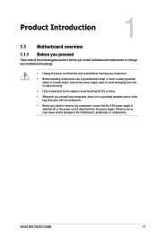
... is detached from the wall socket before you install motherboard components or change any motherboard settings. • Unplug the power cord from the power supply. ASUS WS C621E SAGE 1-1
... is detached from the wall socket before you install motherboard components or change any motherboard settings. • Unplug the power cord from the power supply. ASUS WS C621E SAGE 1-1

User Manual
Page 19
... 1-18 1-18 1-27 1-20 1-26 1-31 1-20 1-10 1-12 1-30 1-22 1-24 1-13 1-22 1-14 1-23 1-13 1-30 1-17 1-9 1-9 1-29 1-21 1-19 1-19 1-31 1-32 ASUS WS C621E SAGE 1-3 SATADOM power setting (3-pin DOM1_PWR1) 9. U.2_3; Intel® C621 Serial ATA 6 Gb/s connectors (7-pin SATA1-8) 11. Chassis Intrusion connector (2-pin INTRUSION1) 14. System panel connector...
... 1-18 1-18 1-27 1-20 1-26 1-31 1-20 1-10 1-12 1-30 1-22 1-24 1-13 1-22 1-14 1-23 1-13 1-30 1-17 1-9 1-9 1-29 1-21 1-19 1-19 1-31 1-32 ASUS WS C621E SAGE 1-3 SATADOM power setting (3-pin DOM1_PWR1) 9. U.2_3; Intel® C621 Serial ATA 6 Gb/s connectors (7-pin SATA1-8) 11. Chassis Intrusion connector (2-pin INTRUSION1) 14. System panel connector...
User Manual
Page 21
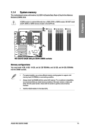
...an optimum compatibility, we recommend that you install memory modules of the same version or data code (D/C) from a DDR, DDR2 or DDR3 module. ASUS WS C621E SAGE 1-5 and 32 GB, and 64 GB LRDIMMs into the DIMM sockets. • For system stability, use a more efficient memory cooling system to... get the correct memory modules. • Visit the ASUS website for the latest QVL. 1.1.4 System memory The motherboard comes with the same CAS Latency. Check with the vendor to support a full memory ...
...an optimum compatibility, we recommend that you install memory modules of the same version or data code (D/C) from a DDR, DDR2 or DDR3 module. ASUS WS C621E SAGE 1-5 and 32 GB, and 64 GB LRDIMMs into the DIMM sockets. • For system stability, use a more efficient memory cooling system to... get the correct memory modules. • Visit the ASUS website for the latest QVL. 1.1.4 System memory The motherboard comes with the same CAS Latency. Check with the vendor to support a full memory ...
User Manual
Page 23
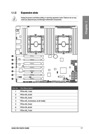
at x8 mode) 5 PCIe x16_5 slot 6 PCIe x16_6 slot 7 PCIe x16_7 slot ASUS WS C621E SAGE 1-7 Chapter 1 Slot No. Slot Description 1 PCIe x16_1 slot 2 PCIe x16_2 slot 3 PCIe x16_3 slot 4 PCIe x16_4 slot (max. Failure to do so may cause you physical injury and damage motherboard components. 1.1.5 Expansion slots Unplug the power cord before adding or removing expansion cards.
at x8 mode) 5 PCIe x16_5 slot 6 PCIe x16_6 slot 7 PCIe x16_7 slot ASUS WS C621E SAGE 1-7 Chapter 1 Slot No. Slot Description 1 PCIe x16_1 slot 2 PCIe x16_2 slot 3 PCIe x16_3 slot 4 PCIe x16_4 slot (max. Failure to do so may cause you physical injury and damage motherboard components. 1.1.5 Expansion slots Unplug the power cord before adding or removing expansion cards.
User Manual
Page 25
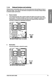
... cable before removing or installing any motherboard component. 2. Reset button Press the reset button to enhance system performance. 1. The button also lights up the system. ASUS WS C621E SAGE 1-9 Chapter 1 1.1.6 Onboard buttons and switches Onboard buttons and switches allow you to fine-tune performance when working on button that allows you to power up...
... cable before removing or installing any motherboard component. 2. Reset button Press the reset button to enhance system performance. 1. The button also lights up the system. ASUS WS C621E SAGE 1-9 Chapter 1 1.1.6 Onboard buttons and switches Onboard buttons and switches allow you to fine-tune performance when working on button that allows you to power up...
User Manual
Page 27
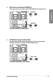
Chapter 1 2. ASUS WS C621E SAGE 1-11 Set to pins 2-3 to enable or disable DDR4 DIMM thermal sensing event pin. 3. DDR4 thermal event setting (3-pin DIMMTRIP1-2) These jumpers allow you to activate the SATA8 support feature. SATADOM power setting (3-pin DOM1_PWR1) This jumper allows SATA8 to support SATADOM which do not need external power connections.
Chapter 1 2. ASUS WS C621E SAGE 1-11 Set to pins 2-3 to enable or disable DDR4 DIMM thermal sensing event pin. 3. DDR4 thermal event setting (3-pin DIMMTRIP1-2) These jumpers allow you to activate the SATA8 support feature. SATADOM power setting (3-pin DOM1_PWR1) This jumper allows SATA8 to support SATADOM which do not need external power connections.
User Manual
Page 29
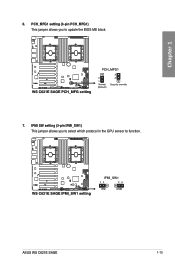
IPMI SW setting (3-pin IPMI_SW1) This jumper allows you to function. PCH_MFG1 setting (3-pin PCH_MFG1) This jumper allows you to select which protocol in the GPU sensor to update the BIOS ME block. 7. ASUS WS C621E SAGE 1-13 Chapter 1 6.
IPMI SW setting (3-pin IPMI_SW1) This jumper allows you to function. PCH_MFG1 setting (3-pin PCH_MFG1) This jumper allows you to select which protocol in the GPU sensor to update the BIOS ME block. 7. ASUS WS C621E SAGE 1-13 Chapter 1 6.
User Manual
Page 31
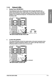
... Location LED helps visually locate and quickly identify the server in error on the server is ON, in sleep mode, or in any motherboard component. ASUS WS C621E SAGE 1-15 Standby Power LED (SBPWR1) The motherboard comes with a standby power LED. The illustration below shows the location of the onboard LED. 2. The green LED...
... Location LED helps visually locate and quickly identify the server in error on the server is ON, in sleep mode, or in any motherboard component. ASUS WS C621E SAGE 1-15 Standby Power LED (SBPWR1) The motherboard comes with a standby power LED. The illustration below shows the location of the onboard LED. 2. The green LED...
User Manual
Page 33
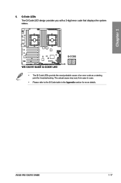
Q-Code LEDs The Q-Code LED design provides you with a 2-digit error code that displays the system status. • The Q-Code LEDs provide the most probable cause of an error code as a starting point for more details. ASUS WS C621E SAGE 1-17 The actual cause may vary from case to case. • Please refer to the Q-Code table in the Appendix section for troubleshooting. Chapter 1 5.
Q-Code LEDs The Q-Code LED design provides you with a 2-digit error code that displays the system status. • The Q-Code LEDs provide the most probable cause of an error code as a starting point for more details. ASUS WS C621E SAGE 1-17 The actual cause may vary from case to case. • Please refer to the Q-Code table in the Appendix section for troubleshooting. Chapter 1 5.
User Manual
Page 35
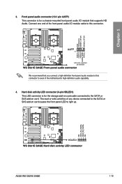
... audio capability. 4. Hard disk activity LED connector (4-pin HDLED1) This LED connector is for the storage add-on card. We recommend that supports HD Audio. ASUS WS C621E SAGE 1-19 Chapter 1 3.
... audio capability. 4. Hard disk activity LED connector (4-pin HDLED1) This LED connector is for the storage add-on card. We recommend that supports HD Audio. ASUS WS C621E SAGE 1-19 Chapter 1 3.
User Manual
Page 37
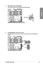
Chapter 1 7. U.2_3; ASUS WS C621E SAGE 1-21 U.2_4) This motherboard comes with U.2 connectors which support PCIe 3.0 x4 NVM Express storage. U.2 connectors (U.2_1; U.2_2; VGA connector (16-1 pin VGA_HDR1) This connector supports the VGA High Dynamic-Range interface. 8.
Chapter 1 7. U.2_3; ASUS WS C621E SAGE 1-21 U.2_4) This motherboard comes with U.2 connectors which support PCIe 3.0 x4 NVM Express storage. U.2 connectors (U.2_1; U.2_2; VGA connector (16-1 pin VGA_HDR1) This connector supports the VGA High Dynamic-Range interface. 8.
User Manual
Page 39
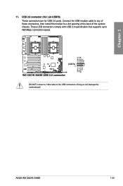
Doing so will damage the motherboard! These USB connectors comply with USB 2.0 specification that supports up to the USB connectors. USB 2.0 connector (10-1 pin USB78) These connectors are for USB 2.0 ports. DO NOT connect a 1394 cable to 480 Mbps connection speed. Connect the USB module cable to any of these connectors, then install the module to a slot opening at the back of the system chassis. ASUS WS C621E SAGE 1-23 Chapter 1 11.
Doing so will damage the motherboard! These USB connectors comply with USB 2.0 specification that supports up to the USB connectors. USB 2.0 connector (10-1 pin USB78) These connectors are for USB 2.0 ports. DO NOT connect a 1394 cable to 480 Mbps connection speed. Connect the USB module cable to any of these connectors, then install the module to a slot opening at the back of the system chassis. ASUS WS C621E SAGE 1-23 Chapter 1 11.
User Manual
Page 41
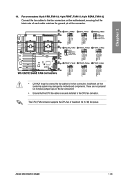
... fan connectors on the fan connectors! • Ensure that the black wire of each cable matches the ground pin of maximum 1A (12 W) fan power. ASUS WS C621E SAGE 1-25 Insufficient air flow inside the system may damage the motherboard components. The CPU_FAN connector supports the CPU fan of the connector. • DO NOT...
... fan connectors on the fan connectors! • Ensure that the black wire of each cable matches the ground pin of maximum 1A (12 W) fan power. ASUS WS C621E SAGE 1-25 Insufficient air flow inside the system may damage the motherboard components. The CPU_FAN connector supports the CPU fan of the connector. • DO NOT...
User Manual
Page 43
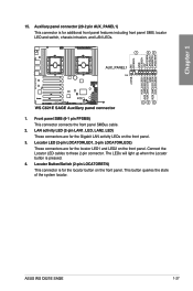
.../Switch (2-pin LOCATORBTN) This connector is pressed. 4. Connect the Locator LED cables to these 2-pin connector. This button queries the state of the system locator. ASUS WS C621E SAGE 1-27 The LEDs will light up when the Locator button is for additional front panel features including front panel SMB, locator LED and switch, chassis...
.../Switch (2-pin LOCATORBTN) This connector is pressed. 4. Connect the Locator LED cables to these 2-pin connector. This button queries the state of the system locator. ASUS WS C621E SAGE 1-27 The LEDs will light up when the Locator button is for additional front panel features including front panel SMB, locator LED and switch, chassis...

User Manual
Page 45
Power Supply SMBus connector (5-pin PSUSMB) This connector allows you enable the ASUS ASMB card. Devices communicate with an SMBus host and/or other SMBus devices using the SMBus interface. Serial port connector (10-1 pin COM1) This connector ... only when you to connect SMBus (System Management Bus) to the PSU (power supply unit) to a slot opening at the back of the system chassis. ASUS WS C621E SAGE 1-29 Please contact ASUS if your need further support 18. Chapter 1 17. Power supply is for a serial (COM) port.
Power Supply SMBus connector (5-pin PSUSMB) This connector allows you enable the ASUS ASMB card. Devices communicate with an SMBus host and/or other SMBus devices using the SMBus interface. Serial port connector (10-1 pin COM1) This connector ... only when you to connect SMBus (System Management Bus) to the PSU (power supply unit) to a slot opening at the back of the system chassis. ASUS WS C621E SAGE 1-29 Please contact ASUS if your need further support 18. Chapter 1 17. Power supply is for a serial (COM) port.
User Manual
Page 47
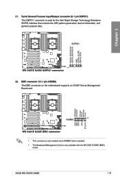
BMC connector (14-1 pin ASMB9) The BMC connector on the motherboard supports an ASUS® Server Management Board card. • This connector is only enabled when ASMB9 Card is installed. • The Baseboard Management Card is used for the Intel Rapid Storage Technology Enterprise SGPIO interface that controls the LED pattern generation, device information, and general purpose data. Chapter 1 22. Serial General Purpose Input/Output connector (6-1 pin SGPIO1) The SGPIO 1 connector is only available with the WS C621E SAGE (BMC) model. 21. ASUS WS C621E SAGE 1-31
BMC connector (14-1 pin ASMB9) The BMC connector on the motherboard supports an ASUS® Server Management Board card. • This connector is only enabled when ASMB9 Card is installed. • The Baseboard Management Card is used for the Intel Rapid Storage Technology Enterprise SGPIO interface that controls the LED pattern generation, device information, and general purpose data. Chapter 1 22. Serial General Purpose Input/Output connector (6-1 pin SGPIO1) The SGPIO 1 connector is only available with the WS C621E SAGE (BMC) model. 21. ASUS WS C621E SAGE 1-31
User Manual
Page 49
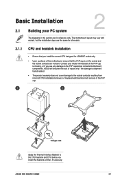
... Installation 2.1 Building your retailer immediately if the PnP cap is missing, or if you see any damage to the PnP cap/socket contacts/motherboard components. ASUS WS C621E SAGE 2-1 ASUS will shoulder the cost of repair only if the damage is shipment/ transit-related. • The product warranty does not cover damage to the CPU...
... Installation 2.1 Building your retailer immediately if the PnP cap is missing, or if you see any damage to the PnP cap/socket contacts/motherboard components. ASUS WS C621E SAGE 2-1 ASUS will shoulder the cost of repair only if the damage is shipment/ transit-related. • The product warranty does not cover damage to the CPU...
User Manual
Page 51
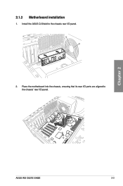
2.1.2 Motherboard installation 1. Install the ASUS Q-Shield to the chassis' rear I /O panel. 2. Place the motherboard into the chassis, ensuring that its rear I/O ports are aligned to the chassis rear I /O panel. Chapter 2 ASUS WS C621E SAGE 2-3
2.1.2 Motherboard installation 1. Install the ASUS Q-Shield to the chassis' rear I /O panel. 2. Place the motherboard into the chassis, ensuring that its rear I/O ports are aligned to the chassis rear I /O panel. Chapter 2 ASUS WS C621E SAGE 2-3
User Manual
Page 53
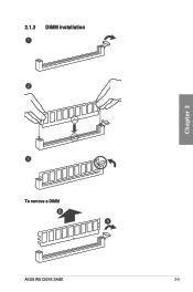
2.1.3 DIMM installation Chapter 2 To remove a DIMM ASUS WS C621E SAGE 2-5
2.1.3 DIMM installation Chapter 2 To remove a DIMM ASUS WS C621E SAGE 2-5
User Manual
Page 55
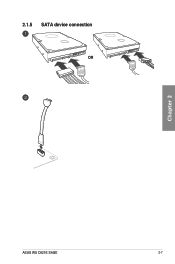
2.1.5 SATA device connection OR Chapter 2 ASUS WS C621E SAGE 2-7
2.1.5 SATA device connection OR Chapter 2 ASUS WS C621E SAGE 2-7


