
T-P5G31 user's manual
Page 3
... System introduction 1.1 Welcome 1-2 1.2 Front panel 1-2 1.2.1 T3-P5G31 front panel 1-2 1.2.2 T4-P5G31 front panel 1-4 1.3 Rear panel 1-6 1.4 Internal components 1-8 Chapter 2: Basic installation 2.1 Preparation 2-2 2.2 Before you proceed 2-2 2.3 Removing the cover 2-3 2.4 Power supply unit 2-4 2.5 CPU installation 2-5 2.5.1 Installing the CPU... Serial ATA disk drive 2-15 2.10 Replacing the power supply unit 2-16 2.11 Replacing the cover 2-17 Chapter 3: Starting up 3.1 Installing an operating system 3-2 3.2 Powering up 3-2 3.3 Support CD information 3-3 3.3.1 Running the support CD...
... System introduction 1.1 Welcome 1-2 1.2 Front panel 1-2 1.2.1 T3-P5G31 front panel 1-2 1.2.2 T4-P5G31 front panel 1-4 1.3 Rear panel 1-6 1.4 Internal components 1-8 Chapter 2: Basic installation 2.1 Preparation 2-2 2.2 Before you proceed 2-2 2.3 Removing the cover 2-3 2.4 Power supply unit 2-4 2.5 CPU installation 2-5 2.5.1 Installing the CPU... Serial ATA disk drive 2-15 2.10 Replacing the power supply unit 2-16 2.11 Replacing the cover 2-17 Chapter 3: Starting up 3.1 Installing an operating system 3-2 3.2 Powering up 3-2 3.3 Support CD information 3-3 3.3.1 Running the support CD...
T-P5G31 user's manual
Page 7
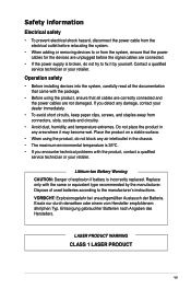
.../outlet in any area where it by the manufacturer. Ersatz nur durch denselben oder einem vom Hersteller empfohlenem ähnljchen Typ. Replace only with the product, contact a qualified service technician or your retailer. VORSICHT: Explosionsgetahr bei unsachgemäßen Austausch der ...keep paper clips, screws, and staples away from the system, ensure that all cables are correctly connected and the power cables are connected. • If the power supply is 35ºC. • If you detect any damage, contact your retailer. Safety information Electrical safety •...
.../outlet in any area where it by the manufacturer. Ersatz nur durch denselben oder einem vom Hersteller empfohlenem ähnljchen Typ. Replace only with the product, contact a qualified service technician or your retailer. VORSICHT: Explosionsgetahr bei unsachgemäßen Austausch der ...keep paper clips, screws, and staples away from the system, ensure that all cables are correctly connected and the power cables are connected. • If the power supply is 35ºC. • If you detect any damage, contact your retailer. Safety information Electrical safety •...

T-P5G31 user's manual
Page 36
... area is 100‑127 V, set the switch to the ATX12V connector on the motherboard. 3. 2.10 Replacing the power supply unit Replace the power supply unit (PSU) after installing the system components and reconnecting the cables. Connect the optical drive power connector. 4. Setting the switch to the ATXPWR connector on the motherboard. 2. C T R BASS REAR S P K SIDE S P K LINE IN...
... area is 100‑127 V, set the switch to the ATX12V connector on the motherboard. 3. 2.10 Replacing the power supply unit Replace the power supply unit (PSU) after installing the system components and reconnecting the cables. Connect the optical drive power connector. 4. Setting the switch to the ATXPWR connector on the motherboard. 2. C T R BASS REAR S P K SIDE S P K LINE IN...


