
T2-R User Manual
Page 4
... the WLAN Card utilities and driver ......... 59 3.6.4 Other support CD options 59 3.6.5 The Control Center utility 60 Chapter 4: Motherboard info 4.1 Introduction 72 4.2 Motherboard layout 72 4.3 Jumper 73 4.4 Internal connectors 74 Chapter 5: BIOS setup 5.1 Managing and updating your BIOS 82 5.1.1 Creating ...a bootable floppy disk 82 5.1.2 Using AFUDOS to copy the current BIOS 83 5.1.3 Using AFUDOS to update the BIOS 84 5.1.4 Using ASUS EZ...
... the WLAN Card utilities and driver ......... 59 3.6.4 Other support CD options 59 3.6.5 The Control Center utility 60 Chapter 4: Motherboard info 4.1 Introduction 72 4.2 Motherboard layout 72 4.3 Jumper 73 4.4 Internal connectors 74 Chapter 5: BIOS setup 5.1 Managing and updating your BIOS 82 5.1.1 Creating ...a bootable floppy disk 82 5.1.2 Using AFUDOS to copy the current BIOS 83 5.1.3 Using AFUDOS to update the BIOS 84 5.1.4 Using ASUS EZ...
T2-R User Manual
Page 8
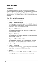
.... The chapter lists the system features, including introduction on Deluxe-Commercial models only). 8 Chapter 2: Basic installation This chapter provides step-by-step instructions on the ASUS Terminator 2 barebone system. Chapter 5: BIOS setup This chapter tells how to install components in the system. 3. This chapter includes the motherboard layout, jumper settings, and connector locations. 5. Chapter...
.... The chapter lists the system features, including introduction on Deluxe-Commercial models only). 8 Chapter 2: Basic installation This chapter provides step-by-step instructions on the ASUS Terminator 2 barebone system. Chapter 5: BIOS setup This chapter tells how to install components in the system. 3. This chapter includes the motherboard layout, jumper settings, and connector locations. 5. Chapter...
T2-R User Manual
Page 10
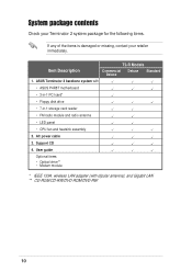
...8226; ASUS P4R8T motherboard • 3-in-1 PCI card* • Floppy disk drive • 7-in-1 storage card reader • FM radio module and radio antenna • LED panel • CPU fan and heatsink assembly 2. Support CD 4. System package contents Check your Terminator 2 system... package for the following items. If any of the items is damaged or missing, contact your retailer immediately. Item Description T2-R Models Commercial Deluxe Deluxe Standard 1.
...8226; ASUS P4R8T motherboard • 3-in-1 PCI card* • Floppy disk drive • 7-in-1 storage card reader • FM radio module and radio antenna • LED panel • CPU fan and heatsink assembly 2. Support CD 4. System package contents Check your Terminator 2 system... package for the following items. If any of the items is damaged or missing, contact your retailer immediately. Item Description T2-R Models Commercial Deluxe Deluxe Standard 1.
T2-R User Manual
Page 12
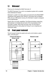
Thank you for the sophisticated. Superb video and audio capabilities, Fast Ethernet/wireless networking, and extensive connectivity are just some of the Terminator 2 system. Commercial Deluxe & Deluxe model Standard model 1 2 1 2 3 4 9 10 MODE 5 6 7 8 11 12 13 14 MODE 3 4 5 6 7 8 15 16 17 18 ... panel includes the system and audio control buttons, system LEDs, and LED panel. The ASUS Terminator 2 is an all-in a stylish mini-tower casing and powered by the ASUS P4R8T motherboard that supports Intel® Pentium® 4 processor with a versatile home entertainment feature. ...
Thank you for the sophisticated. Superb video and audio capabilities, Fast Ethernet/wireless networking, and extensive connectivity are just some of the Terminator 2 system. Commercial Deluxe & Deluxe model Standard model 1 2 1 2 3 4 9 10 MODE 5 6 7 8 11 12 13 14 MODE 3 4 5 6 7 8 15 16 17 18 ... panel includes the system and audio control buttons, system LEDs, and LED panel. The ASUS Terminator 2 is an all-in a stylish mini-tower casing and powered by the ASUS P4R8T motherboard that supports Intel® Pentium® 4 processor with a versatile home entertainment feature. ...
T2-R User Manual
Page 19
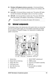
...slot 11. Floppy disk drive 4. ASUS P4R8T motherboard 8. DIMM sockets 9. See page 58 for the wireless LAN adapter LED indications. 1.5 Internal components The illustration below is transmitting or receiving data. Chassis fan 7. PCI slot (with an installed PCI card) ASUS Terminator 2 barebone system 19 Front panel cover...bay 3. AIR LED. (Commercial Deluxe models only.) This green LED blinks when the wireless LAN adapter is the internal view of the wireless LAN adapter. 23. Wireless LAN adapter antenna connector. (Commercial Deluxe models only.) This connects the dipolar...
...slot 11. Floppy disk drive 4. ASUS P4R8T motherboard 8. DIMM sockets 9. See page 58 for the wireless LAN adapter LED indications. 1.5 Internal components The illustration below is transmitting or receiving data. Chassis fan 7. PCI slot (with an installed PCI card) ASUS Terminator 2 barebone system 19 Front panel cover...bay 3. AIR LED. (Commercial Deluxe models only.) This green LED blinks when the wireless LAN adapter is the internal view of the wireless LAN adapter. 23. Wireless LAN adapter antenna connector. (Commercial Deluxe models only.) This connects the dipolar...
T2-R User Manual
Page 22
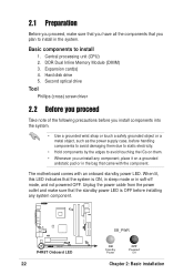
Basic components to install in soft-off mode, and not powered OFF. Expansion card(s) 4. Hard disk drive 5. The motherboard comes with the component. 2.1 Preparation Before you proceed, make sure that the system is OFF before handling components to avoid damaging them due to static ...
Basic components to install in soft-off mode, and not powered OFF. Expansion card(s) 4. Hard disk drive 5. The motherboard comes with the component. 2.1 Preparation Before you proceed, make sure that the system is OFF before handling components to avoid damaging them due to static ...

T2-R User Manual
Page 24
... floppy disk drive power plugs. 3. Push the PSU towards the front 4 6 panel for about half an inch. 6. Lay the system on its side on the motherboard. 8.
... floppy disk drive power plugs. 3. Push the PSU towards the front 4 6 panel for about half an inch. 6. Lay the system on its side on the motherboard. 8.
T2-R User Manual
Page 25
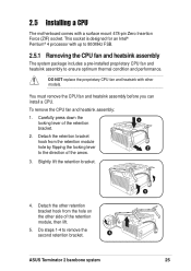
.... 2.5.1 Removing the CPU fan and heatsink assembly The system package includes a pre-installed proprietary CPU fan and heatsink assembly to remove the second retention bracket. 4 ASUS Terminator 2 barebone system 3 25 Detach the retention bracket hook from the hole on the other side of the retention bracket. 2. Carefully press down the 1 locking lever...
.... 2.5.1 Removing the CPU fan and heatsink assembly The system package includes a pre-installed proprietary CPU fan and heatsink assembly to remove the second retention bracket. 4 ASUS Terminator 2 barebone system 3 25 Detach the retention bracket hook from the hole on the other side of the retention bracket. 2. Carefully press down the 1 locking lever...

T2-R User Manual
Page 26
... the socket until it up to a 90° angle. 3. Disconnect the CPU fan cable from the CPU fan connector on the motherboard. 2. Locate the 478-pin CPU socket on the motherboard. 7. The lever clicks on the side tab to secure the CPU. Push down the socket lever to indicate that its marked...
... the socket until it up to a 90° angle. 3. Disconnect the CPU fan cable from the CPU fan connector on the motherboard. 2. Locate the 478-pin CPU socket on the motherboard. 7. The lever clicks on the side tab to secure the CPU. Push down the socket lever to indicate that its marked...
T2-R User Manual
Page 27
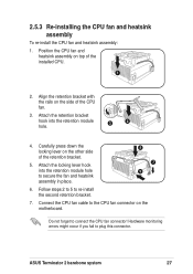
... CPU. 1 2. Do not forget to plug this connector. Hardware monitoring errors might occur if you fail to connect the CPU fan connector! ASUS Terminator 2 barebone system 27 Position the CPU fan and heatsink assembly on the other side of the CPU fan. 3. Attach the locking lever hook... into the retention module 3 2 hole. 4. Align the retention bracket with the rails on the motherboard. Follow steps 2 to 5 to the CPU fan connector on the side of the retention bracket. 5. 2.5.3 Re-installing the CPU fan and heatsink ...
... CPU. 1 2. Do not forget to plug this connector. Hardware monitoring errors might occur if you fail to connect the CPU fan connector! ASUS Terminator 2 barebone system 27 Position the CPU fan and heatsink assembly on the other side of the CPU fan. 3. Attach the locking lever hook... into the retention module 3 2 hole. 4. Align the retention bracket with the rails on the motherboard. Follow steps 2 to 5 to the CPU fan connector on the side of the retention bracket. 5. 2.5.3 Re-installing the CPU fan and heatsink ...
T2-R User Manual
Page 28
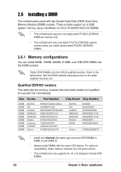
... latency. For optimum compatibility, obtain memory modules from ASUS qualified vendors. Obtain DDR DIMMs only from the same vendor. • This motherboard only supports x4, x8, x16 chips/per channel only. • This motherboard may only detect PC2700 (DDR333) system memory when ...You can install 64MB, 128MB, 256MB, 512MB, and 1GB DDR DIMMs into the DIMM sockets. Visit the ASUS website (www.asus.com) for use with this motherboard. Infineon 46V32M8 A2S56D30BTP TMD7608F8E50D K4H560838D-TCC4 K4H560838D-TCCC W9425088H-5 V58C2256804SAT5 -- Size Vendor Part Number Chip Brand Chip ...
... latency. For optimum compatibility, obtain memory modules from ASUS qualified vendors. Obtain DDR DIMMs only from the same vendor. • This motherboard only supports x4, x8, x16 chips/per channel only. • This motherboard may only detect PC2700 (DDR333) system memory when ...You can install 64MB, 128MB, 256MB, 512MB, and 1GB DDR DIMMs into the DIMM sockets. Visit the ASUS website (www.asus.com) for use with this motherboard. Infineon 46V32M8 A2S56D30BTP TMD7608F8E50D K4H560838D-TCC4 K4H560838D-TCCC W9425088H-5 V58C2256804SAT5 -- Size Vendor Part Number Chip Brand Chip ...
T2-R User Manual
Page 29
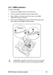
Align a DIMM on the socket such that it fits in place and the DIMM is keyed with a notch so that the notch on the DIMM matches the break on the motherboard. 2. Firmly insert the DIMM into a socket to avoid damaging the DIMM! Retaining clips 3 2 4 2 4 1 A DDR DIMM is properly seated. Locate the two DIMM sockets on the socket. 4. ASUS Terminator 2 barebone system 29 Unlock a socket by pressing the retaining clips outward. 3. 2.6.2 DIMM installation To install a DDR DIMM. 1. DO NOT force a DIMM into the socket until the retaining clips snap back in only one direction.
Align a DIMM on the socket such that it fits in place and the DIMM is keyed with a notch so that the notch on the DIMM matches the break on the motherboard. 2. Firmly insert the DIMM into a socket to avoid damaging the DIMM! Retaining clips 3 2 4 2 4 1 A DDR DIMM is properly seated. Locate the two DIMM sockets on the socket. 4. ASUS Terminator 2 barebone system 29 Unlock a socket by pressing the retaining clips outward. 3. 2.6.2 DIMM installation To install a DDR DIMM. 1. DO NOT force a DIMM into the socket until the retaining clips snap back in only one direction.

T2-R User Manual
Page 30
...AGP 4X (+1.5V) cards. Unplug the power cord before adding or removing expansion cards. Install only +0.8V or +1.5V AGP cards. For Commercial Deluxe models, a 3-in-1 PCI card is pre-installed in the PCI slot. You may refer to install expansion cards. When you buy an ...sure that you ask for optimum performance and overclocking stability. 2.7 Installing an expansion card In the future, you physical injury and damage the motherboard. 30 Chapter 2: Basic installation The following sub-sections describe the slots and the expansion cards that comply with +0.8V or +1.5V specification....
...AGP 4X (+1.5V) cards. Unplug the power cord before adding or removing expansion cards. Install only +0.8V or +1.5V AGP cards. For Commercial Deluxe models, a 3-in-1 PCI card is pre-installed in the PCI slot. You may refer to install expansion cards. When you buy an ...sure that you ask for optimum performance and overclocking stability. 2.7 Installing an expansion card In the future, you physical injury and damage the motherboard. 30 Chapter 2: Basic installation The following sub-sections describe the slots and the expansion cards that comply with +0.8V or +1.5V specification....

T2-R User Manual
Page 32
... Mode when used C shared -- -- -- -- When using a PCI card on the system and change the necessary BIOS settings, if any. Install the software drivers for this motherboard PCI slot 1 AGP slot Onboard USB controller HC0 Onboard USB controller HC1 Onboard USB 2.0 controller Onboard LAN Onboard Audio A -- Otherwise, conflicts will arise between the...
... Mode when used C shared -- -- -- -- When using a PCI card on the system and change the necessary BIOS settings, if any. Install the software drivers for this motherboard PCI slot 1 AGP slot Onboard USB controller HC0 Onboard USB controller HC1 Onboard USB 2.0 controller Onboard LAN Onboard Audio A -- Otherwise, conflicts will arise between the...

T2-R User Manual
Page 34
... the front panel cover. 14. Connect a power cable from the power supply unit to the 4-pin connector at the back of the optical drive. On Deluxe models, re-connect the LED panel and the front 13 audio button panel cables to the chassis holes as indicated. 14 34 Chapter 2: Basic installation... one end of the optical drive audio cable to the power connector at the back of the optical drive, matching the red stripe on the motherboard. 8. See page 76 for details. 9. Re-install the front panel cover by aligning its hooks with Pin 1 on the...
... the front panel cover. 14. Connect a power cable from the power supply unit to the 4-pin connector at the back of the optical drive. On Deluxe models, re-connect the LED panel and the front 13 audio button panel cables to the chassis holes as indicated. 14 34 Chapter 2: Basic installation... one end of the optical drive audio cable to the power connector at the back of the optical drive, matching the red stripe on the motherboard. 8. See page 76 for details. 9. Re-install the front panel cover by aligning its hooks with Pin 1 on the...

T2-R User Manual
Page 36
See page 76 for the location of the 40-pin IDE cable to the HDD power connector. 8 10. Re-install the HDD tray and HDD inside the chassis by loching the tray slots to the primary IDE connector (blue connector labeled PRI_IDE) on the drive. 9. Connect the other end of the 9 IDE ribbon cable to the chassis hooks. 6 7. 6. Connect a 4-pin power plug from the power supply unit to the IDE connector on the motherboard. Secure the tray with the screw you removed earlier . 7 8. Connect one end of the primary IDE connector. 36 Chapter 2: Basic installation
See page 76 for the location of the 40-pin IDE cable to the HDD power connector. 8 10. Re-install the HDD tray and HDD inside the chassis by loching the tray slots to the primary IDE connector (blue connector labeled PRI_IDE) on the drive. 9. Connect the other end of the 9 IDE ribbon cable to the chassis hooks. 6 7. 6. Connect a 4-pin power plug from the power supply unit to the IDE connector on the motherboard. Secure the tray with the screw you removed earlier . 7 8. Connect one end of the primary IDE connector. 36 Chapter 2: Basic installation

T2-R User Manual
Page 44
...the system power button ( ) to turn on the Audio DJ feature. See page 55 for general reference only. 3.1 Installing an operating system Terminator 2 supports Windows® 2000/XP operating systems (OS). Always install the latest OS version and corresponding updates so you can maximize the features ... for details. Press the button to enter the OS. Press to put the system in Audio DJ mode MODE Press to your hardware. Motherboard settings and hardware options vary, so use the setup procedures presented in the front panel. Refer to enter the system OS In Windows®...
...the system power button ( ) to turn on the Audio DJ feature. See page 55 for general reference only. 3.1 Installing an operating system Terminator 2 supports Windows® 2000/XP operating systems (OS). Always install the latest OS version and corresponding updates so you can maximize the features ... for details. Press the button to enter the OS. Press to put the system in Audio DJ mode MODE Press to your hardware. Motherboard settings and hardware options vary, so use the setup procedures presented in the front panel. Refer to enter the system OS In Windows®...

T2-R User Manual
Page 45
...the support CD, place the CD in your computer. AD1888 Driver and Application This item installs the AD1888 audio driver and SoundMax® application. ASUS Terminator 2 barebone system 45 Install the necessary drivers to run the CD. 3.3.2 Drivers menu The drivers menu shows the available device drivers if the ...your computer, browse the contents of the support CD to install the ATI All In One Driver for details. See page 48 for the P4R8T motherboard. ATI All In One Driver Click this item to locate the file ASSETUP.EXE from the BIN folder. If your system comes with a ...
...the support CD, place the CD in your computer. AD1888 Driver and Application This item installs the AD1888 audio driver and SoundMax® application. ASUS Terminator 2 barebone system 45 Install the necessary drivers to run the CD. 3.3.2 Drivers menu The drivers menu shows the available device drivers if the ...your computer, browse the contents of the support CD to install the ATI All In One Driver for details. See page 48 for the P4R8T motherboard. ATI All In One Driver Click this item to locate the file ASSETUP.EXE from the BIN folder. If your system comes with a ...

T2-R User Manual
Page 46
...details. 3.3.3 Utilities The Utilities tab displays the applications and softwares that allows you keep your computer in to an FM radio station. ASUS PC Probe This utility continuously monitors vital system information such as fan rotations, CPU temperature, and system voltages, and alerts you on... and drivers. PC-CILLIN 2002 This item installs the PC-cillin 2002 anti-virus program. ASUS Radio Application This item installs the ASUS radio application that the motherboard supports. ADOBE Acrobat Reader V5.0 This item installs the Adobe® Acrobat Reader®. See page 89 for...
...details. 3.3.3 Utilities The Utilities tab displays the applications and softwares that allows you keep your computer in to an FM radio station. ASUS PC Probe This utility continuously monitors vital system information such as fan rotations, CPU temperature, and system voltages, and alerts you on... and drivers. PC-CILLIN 2002 This item installs the PC-cillin 2002 anti-virus program. ASUS Radio Application This item installs the ASUS radio application that the motherboard supports. ADOBE Acrobat Reader V5.0 This item installs the Adobe® Acrobat Reader®. See page 89 for...

T2-R User Manual
Page 47
ASUS Terminator 2 barebone system 47 ASUS Screensaver This item installs the ASUS Screensaver. 3.3.4 ASUS contact information Click the Contact tab to display the ASUS contact information. 3.3.5 Other information The icons on the top right of the screen provide additional information on the motherboard and the contents of the support CD.
ASUS Terminator 2 barebone system 47 ASUS Screensaver This item installs the ASUS Screensaver. 3.3.4 ASUS contact information Click the Contact tab to display the ASUS contact information. 3.3.5 Other information The icons on the top right of the screen provide additional information on the motherboard and the contents of the support CD.


