
T2-PH2 User''s Manual for English Edition
Page 4
... FM radio station 3-11 3.5.3 Presetting a station 3-12 3.5.4 Adjusting the volume 3-12 Chapter 4: Motherboard Info 4.1 Introduction 4-2 4.2 Motherboard layout 4-2 4.3 Jumpers 4-3 4.4 Connectors 4-5 Chapter 5: BIOS Information 5.1 Managing and updating your BIOS 5-2 5.1.1 Creating a bootable floppy disk 5-2 5.1.2 ASUS EZ Flash utility 5-3 5.1.3 AFUDOS utility 5-4 5.1.4 ASUS CrashFree BIOS 2 utility 5-6 5.1.5 ASUS Update utility 5-8 5.2 BIOS setup program 5-11 5.2.1 BIOS menu screen 5-12 5.2.2 Menu bar...
... FM radio station 3-11 3.5.3 Presetting a station 3-12 3.5.4 Adjusting the volume 3-12 Chapter 4: Motherboard Info 4.1 Introduction 4-2 4.2 Motherboard layout 4-2 4.3 Jumpers 4-3 4.4 Connectors 4-5 Chapter 5: BIOS Information 5.1 Managing and updating your BIOS 5-2 5.1.1 Creating a bootable floppy disk 5-2 5.1.2 ASUS EZ Flash utility 5-3 5.1.3 AFUDOS utility 5-4 5.1.4 ASUS CrashFree BIOS 2 utility 5-6 5.1.5 ASUS Update utility 5-8 5.2 BIOS setup program 5-11 5.2.1 BIOS menu screen 5-12 5.2.2 Menu bar...
T2-PH2 User''s Manual for English Edition
Page 8
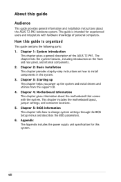
... supply unit specification for experienced users and integrators with the system. viii This chapter includes the motherboard layout, jumper settings, and connector locations. 5. Chapter 4: Motherboard information This chapter gives information about the ASUS T2-PH2 barebone system. Chapter 5: BIOS information This chapter tells how to install components in the system. 3. How this guide...
... supply unit specification for experienced users and integrators with the system. viii This chapter includes the motherboard layout, jumper settings, and connector locations. 5. Chapter 4: Motherboard information This chapter gives information about the ASUS T2-PH2 barebone system. Chapter 5: BIOS information This chapter tells how to install components in the system. 3. How this guide...
T2-PH2 User''s Manual for English Edition
Page 10
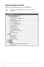
Support CD 4. Cables • AC power cable • Ultra ATA 66 cable • Serial ATA cable • Serial ATA power cable 3. ASUS T2-PH2 barebone system with • ASUS motherboard • 250 W Passive PFC power supply unit • Gigabit LAN port • CPU fan and heatsink assembly • 2 x 5.25" drive bays •...• Optical drive (CD-ROM/CD-RW/DVD-ROM/DVD-RW) • Floppy disk drive x System package contents Check your T2-PH2 system package for the following items. If any of the items is damaged or missing, contact your retailer immediately. Item description 1.
Support CD 4. Cables • AC power cable • Ultra ATA 66 cable • Serial ATA cable • Serial ATA power cable 3. ASUS T2-PH2 barebone system with • ASUS motherboard • 250 W Passive PFC power supply unit • Gigabit LAN port • CPU fan and heatsink assembly • 2 x 5.25" drive bays •...• Optical drive (CD-ROM/CD-RW/DVD-ROM/DVD-RW) • Floppy disk drive x System package contents Check your T2-PH2 system package for the following items. If any of the items is damaged or missing, contact your retailer immediately. Item description 1.
T2-PH2 User''s Manual for English Edition
Page 12
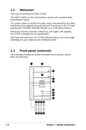
1.1 Welcome! With audio functions, extensive connectivity, and Gigabit LAN capability, the T2-PH2 is an all-in the 775-land package with a versatile home entertainment feature. The ASUS T2-PH2 is designed for the sophisticated. Thank you for your computing and multimedia needs! 1.2 Front panel (external...the ASUS motherboard that supports the Intel® Pentium® 4 processor in -one barebone system with 533/800/1066 MHz FSB and up to 2 GB system memory. With these and many more, the T2-PH2 definitely delivers the cutting edge technology for choosing the ASUS T2-PH2!
1.1 Welcome! With audio functions, extensive connectivity, and Gigabit LAN capability, the T2-PH2 is an all-in the 775-land package with a versatile home entertainment feature. The ASUS T2-PH2 is designed for the sophisticated. Thank you for your computing and multimedia needs! 1.2 Front panel (external...the ASUS motherboard that supports the Intel® Pentium® 4 processor in -one barebone system with 533/800/1066 MHz FSB and up to 2 GB system memory. With these and many more, the T2-PH2 definitely delivers the cutting edge technology for choosing the ASUS T2-PH2!
T2-PH2 User''s Manual for English Edition
Page 19
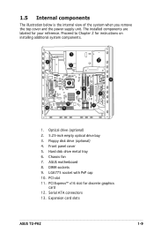
...with PnP cap 10. Serial ATA connectors 13. Proceed to Chapter 2 for discrete graphics card 12. Floppy disk drive (optional) 4. ASUS motherboard 8. DIMM sockets 9. PCI slot 11. Hard disk drive metal tray 6. Chassis fan 7. 1.5 Internal components The illustration below is the ...™ x16 slot for instructions on installing additional system components. 1 6 3 2 9 8 7 4 5 10 12 13 11 1. Expansion card slots ASUS T2-PH2 1-9 The installed components are labeled for your reference. Front panel cover 5. Optical drive (optional) 2. 5.25-inch empty optical drive bay 3.
...with PnP cap 10. Serial ATA connectors 13. Proceed to Chapter 2 for discrete graphics card 12. Floppy disk drive (optional) 4. ASUS motherboard 8. DIMM sockets 9. PCI slot 11. Hard disk drive metal tray 6. Chassis fan 7. 1.5 Internal components The illustration below is the ...™ x16 slot for instructions on installing additional system components. 1 6 3 2 9 8 7 4 5 10 12 13 11 1. Expansion card slots ASUS T2-PH2 1-9 The installed components are labeled for your reference. Front panel cover 5. Optical drive (optional) 2. 5.25-inch empty optical drive bay 3.

T2-PH2 User''s Manual for English Edition
Page 22
... by the edges to avoid touching the ICs on a grounded antistatic pad or in the bag that came with an onboard standby power LED. The motherboard comes with the component. Basic components to install 1. DDR2 Dual Inline Memory Module (DIMM) 3. Hard disk drive 5. 2.1 Preparation Before you proceed, make sure that the...
... by the edges to avoid touching the ICs on a grounded antistatic pad or in the bag that came with an onboard standby power LED. The motherboard comes with the component. Basic components to install 1. DDR2 Dual Inline Memory Module (DIMM) 3. Hard disk drive 5. 2.1 Preparation Before you proceed, make sure that the...
T2-PH2 User''s Manual for English Edition
Page 24
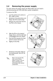
... half an inch. 6. Slightly lift the PSU. 7. The unit may accidentally drop and damage other system components. Lay the system on its side on the motherboard, then set the PSU aside. Remove the screw that secures the PSU to hold or support it firmly. Disconnect the power plugs on a fl...
... half an inch. 6. Slightly lift the PSU. 7. The unit may accidentally drop and damage other system components. Lay the system on its side on the motherboard, then set the PSU aside. Remove the screw that secures the PSU to hold or support it firmly. Disconnect the power plugs on a fl...
T2-PH2 User''s Manual for English Edition
Page 25
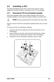
... thermal condition and performance. Disconnect the CPU fan cable from the CPU fan connector on the motherboard. 2. Using a Phillips screw driver, remove and set it aside. 2 2 2 2 1 3 ASUS T2-PH2 2-5 You must remove the CPU fan and heatsink assembly before you can install a CPU. ...To remove the CPU fan and heatsink assembly: 1. 2.5 Installing a CPU The ASUS motherboard comes with other models. DO NOT replace the proprietary CPU fan and...
... thermal condition and performance. Disconnect the CPU fan cable from the CPU fan connector on the motherboard. 2. Using a Phillips screw driver, remove and set it aside. 2 2 2 2 1 3 ASUS T2-PH2 2-5 You must remove the CPU fan and heatsink assembly before you can install a CPU. ...To remove the CPU fan and heatsink assembly: 1. 2.5 Installing a CPU The ASUS motherboard comes with other models. DO NOT replace the proprietary CPU fan and...

T2-PH2 User''s Manual for English Edition
Page 26
Contact your left. 2-6 Chapter 2: Basic installation ASUS will process Return Merchandise Authorization (RMA) requests only if the motherboard comes with installation instructions for the CPU, heatsink, and the retention mechanism. ASUS will shoulder the cost of the PnP cap. If the instructions in this section ...do not match the CPU documentation, follow the latter. • Check your motherboard to make sure that the PnP cap is shipment/...
Contact your left. 2-6 Chapter 2: Basic installation ASUS will process Return Merchandise Authorization (RMA) requests only if the motherboard comes with installation instructions for the CPU, heatsink, and the retention mechanism. ASUS will shoulder the cost of the PnP cap. If the instructions in this section ...do not match the CPU documentation, follow the latter. • Check your motherboard to make sure that the PnP cap is shipment/...
T2-PH2 User''s Manual for English Edition
Page 29
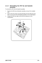
2.5.3 Reinstalling the CPU fan and heatsink assembly To reinstall the CPU fan and heatsink assembly: 1. Position the CPU fan and heatsink assembly on the motherboard. 2 2 2 2 3 1 ASUS T2-PH2 2-9 Drive in the four screws you removed earlier into the CPU fan screw holes to secure the fan and heatsink assembly to the CPU fan connector on top of the installed CPU. 2. Connect the CPU fan cable to the motherboard. 3.
2.5.3 Reinstalling the CPU fan and heatsink assembly To reinstall the CPU fan and heatsink assembly: 1. Position the CPU fan and heatsink assembly on the motherboard. 2 2 2 2 3 1 ASUS T2-PH2 2-9 Drive in the four screws you removed earlier into the CPU fan screw holes to secure the fan and heatsink assembly to the CPU fan connector on top of the installed CPU. 2. Connect the CPU fan cable to the motherboard. 3.

T2-PH2 User''s Manual for English Edition
Page 30
... than the recommended configurations may detect less than 2 GB system memory when you installed two 1 GB DDR2 memory. • This motherboard does not support memory modules made up of 128 Mb chips or double-sided x16 memory modules. 2-10 Chapter 2: Basic installation The following ...with two Double Data Rate 2 (DDR2) Dual Inline Memory Module (DIMM) sockets. DIMM_A1 DIMM_B1 112 Pins 128 Pins 2.6 Installing a DIMM The system motherboard comes with the same CAS latency. Use any of the sockets: ® 240-pin DDR2 DIMM Sockets 2.6.1 Memory configurations You may install up to ...
... than the recommended configurations may detect less than 2 GB system memory when you installed two 1 GB DDR2 memory. • This motherboard does not support memory modules made up of 128 Mb chips or double-sided x16 memory modules. 2-10 Chapter 2: Basic installation The following ...with two Double Data Rate 2 (DDR2) Dual Inline Memory Module (DIMM) sockets. DIMM_A1 DIMM_B1 112 Pins 128 Pins 2.6 Installing a DIMM The system motherboard comes with the same CAS latency. Use any of the sockets: ® 240-pin DDR2 DIMM Sockets 2.6.1 Memory configurations You may install up to ...
T2-PH2 User''s Manual for English Edition
Page 33
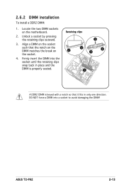
Unlock a socket by pressing the retaining clips outward. 3 3. ASUS T2-PH2 2-13 Firmly insert the DIMM into a socket to avoid damaging the DIMM! DO NOT force a DIMM into the socket until the retaining clips snap back in only one direction. Align a DIMM on the motherboard. Locate the two DIMM sockets on the socket such that it fits in place and the DIMM is properly seated. 1 A DDR2 DIMM is keyed with a notch so that the notch on the DIMM matches the break on the socket. 2 2 4 4 4. 2.6.2 DIMM installation To install a DDR2 DIMM: 1. Retaining clips 2.
Unlock a socket by pressing the retaining clips outward. 3 3. ASUS T2-PH2 2-13 Firmly insert the DIMM into a socket to avoid damaging the DIMM! DO NOT force a DIMM into the socket until the retaining clips snap back in only one direction. Align a DIMM on the motherboard. Locate the two DIMM sockets on the socket such that it fits in place and the DIMM is properly seated. 1 A DDR2 DIMM is keyed with a notch so that the notch on the DIMM matches the break on the socket. 2 2 4 4 4. 2.6.2 DIMM installation To install a DDR2 DIMM: 1. Retaining clips 2.
T2-PH2 User''s Manual for English Edition
Page 34
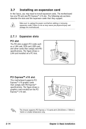
The figure shows a graphics card installed on a PCI slot. The motherboard has one PCI and one PCI Express™ x16 slot. The following sub-sections describe the slots and the expansion cards that comply with PCI .... The chassis supports PCI Express x 16 cards with PCI specifications. 2.7 Installing an expansion card In the future, you physical injury and damage the motherboard. 2.7.1 Expansion slots PCI slot The PCI slots support PCI cards such as a LAN card, SCSI card, USB card, and other cards that comply with 204...
The figure shows a graphics card installed on a PCI slot. The motherboard has one PCI and one PCI Express™ x16 slot. The following sub-sections describe the slots and the expansion cards that comply with PCI .... The chassis supports PCI Express x 16 cards with PCI specifications. 2.7 Installing an expansion card In the future, you physical injury and damage the motherboard. 2.7.1 Expansion slots PCI slot The PCI slots support PCI cards such as a LAN card, SCSI card, USB card, and other cards that comply with 204...
T2-PH2 User''s Manual for English Edition
Page 36
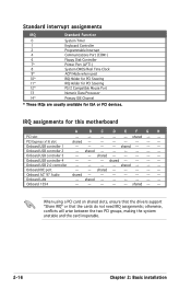
...* IRQ Holder for PCI Steering 12* PS/2 Compatible Mouse Port 13 Numeric Data Processor 14* Primary IDE Channel * These IRQs are usually available for this motherboard A B C D E F G H PCI slot -- -- -- -- -- IRQ assignments for ISA or PCI devices. Onboard ACʼ 97 Audio shared...
...* IRQ Holder for PCI Steering 12* PS/2 Compatible Mouse Port 13 Numeric Data Processor 14* Primary IDE Channel * These IRQs are usually available for this motherboard A B C D E F G H PCI slot -- -- -- -- -- IRQ assignments for ISA or PCI devices. Onboard ACʼ 97 Audio shared...
T2-PH2 User''s Manual for English Edition
Page 38
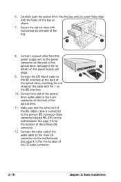
... PRI_IDE) on the bay as shown. 7. Connect one side of the optical drive, matching the red stripe on the cable with the holes on the motherboard. See page 2-25 for details on one end of the optical drive audio cable to the 4-pin connector at the back of the audio cable... 4-pin CD connector on the IDE interface. 10. Carefully push the optical drive into the bay until its screw holes align with Pin 1 on the motherboard. Make sure that the other end of the optical drive. 6. Secure the optical drive with two screws on the power supply unit plugs. 9.
... PRI_IDE) on the bay as shown. 7. Connect one side of the optical drive, matching the red stripe on the cable with the holes on the motherboard. See page 2-25 for details on one end of the optical drive audio cable to the 4-pin connector at the back of the audio cable... 4-pin CD connector on the IDE interface. 10. Carefully push the optical drive into the bay until its screw holes align with Pin 1 on the motherboard. Make sure that the other end of the optical drive. 6. Secure the optical drive with two screws on the power supply unit plugs. 9.

T2-PH2 User''s Manual for English Edition
Page 40
... holes align with two screws. 33 4. Connect the floppy disk drive signal cable to the floppy disk drive connector (labeled FLOPPY) on the motherboard. See page 2-25 for a floppy disk drive. Connect the other end of the signal cable to the signal connector at the back of section...
... holes align with two screws. 33 4. Connect the floppy disk drive signal cable to the floppy disk drive connector (labeled FLOPPY) on the motherboard. See page 2-25 for a floppy disk drive. Connect the other end of the signal cable to the signal connector at the back of section...
T2-PH2 User''s Manual for English Edition
Page 42
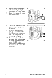
... the HDD power connector. Connect the other end of the 40-pin IDE cable to the primary IDE connector (blue connector labeled PRI_IDE) on the motherboard. Connect one end of the IDE ribbon cable to the IDE connector on the 8 power supply unit plugs. 9 10. Connect a 4-pin power plug from the...
... the HDD power connector. Connect the other end of the 40-pin IDE cable to the primary IDE connector (blue connector labeled PRI_IDE) on the motherboard. Connect one end of the IDE ribbon cable to the IDE connector on the 8 power supply unit plugs. 9 10. Connect a 4-pin power plug from the...
T2-PH2 User''s Manual for English Edition
Page 43
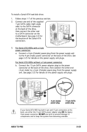
...) power plug 15-pin SATA power plug If your Serial ATA HDD has both to prevent damage to components and to a SATA connector on the motherboard. See page 2-25 for 2 the location of the supplied 7-pin SATA cable (right angle side) to a 4-pin (female) power plug from the power supply unit..., then connect the other end (4-pin male) to the SATA connector at the back of the previous section. 2. To install a Serial ATA hard disk drive: 1. ASUS T2-PH2 2-23
...) power plug 15-pin SATA power plug If your Serial ATA HDD has both to prevent damage to components and to a SATA connector on the motherboard. See page 2-25 for 2 the location of the supplied 7-pin SATA cable (right angle side) to a 4-pin (female) power plug from the power supply unit..., then connect the other end (4-pin male) to the SATA connector at the back of the previous section. 2. To install a Serial ATA hard disk drive: 1. ASUS T2-PH2 2-23

T2-PH2 User''s Manual for English Edition
Page 44
... the PSU cables do not interfere with the screw you removed earlier. Connect the 24-pin ATX power plug to the ATX12V connector on the motherboard. 2. Slide the PSU toward the direction of power connectors. 2 1 3. To reinstall the PSU: 1. Align the PSU side hook with the 4 3 metal slot located on the...
... the PSU cables do not interfere with the screw you removed earlier. Connect the 24-pin ATX power plug to the ATX12V connector on the motherboard. 2. Slide the PSU toward the direction of power connectors. 2 1 3. To reinstall the PSU: 1. Align the PSU side hook with the 4 3 metal slot located on the...

T2-PH2 User''s Manual for English Edition
Page 48
...utility drivers that enhance the system features. • Screen display and driver options may not be the same for general reference only. Visit the ASUS website for more information. 3.2 Powering up 3.1 Installing an operating system The barebone system supports Windows® 2000/XP operating systems (OS). ...mode, pressing the button shuts down, restarts, or puts the system in sleep mode (S3) depending on the Audio DJ feature. Because motherboard settings and hardware options vary, use the setup procedures presented in Audio DJ mode MODE Press to enter the OS. Press to put the ...
...utility drivers that enhance the system features. • Screen display and driver options may not be the same for general reference only. Visit the ASUS website for more information. 3.2 Powering up 3.1 Installing an operating system The barebone system supports Windows® 2000/XP operating systems (OS). ...mode, pressing the button shuts down, restarts, or puts the system in sleep mode (S3) depending on the Audio DJ feature. Because motherboard settings and hardware options vary, use the setup procedures presented in Audio DJ mode MODE Press to enter the OS. Press to put the ...