User Guide
Page 13
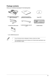
xiii Package contents Check your motherboard package for the following items User Manual ASUS SABERTOOTH Z97 MARK 2/ USB 3.1 motherboard Technical documentations, certification and warranty card Support DVD 4 x Serial ATA 6.0 Gb/s cables 1 x ASUS SLI™ bridge connector (7 cm) 1 x ASUS Q-Shield 1 x 2-in-1 ASUS Q-Connector kit • If any of the above items is damaged or missing, contact your retailer. • The illustrated items above are for reference only. Actual product specifications may vary with different models.
xiii Package contents Check your motherboard package for the following items User Manual ASUS SABERTOOTH Z97 MARK 2/ USB 3.1 motherboard Technical documentations, certification and warranty card Support DVD 4 x Serial ATA 6.0 Gb/s cables 1 x ASUS SLI™ bridge connector (7 cm) 1 x ASUS Q-Shield 1 x 2-in-1 ASUS Q-Connector kit • If any of the above items is damaged or missing, contact your retailer. • The illustrated items above are for reference only. Actual product specifications may vary with different models.
User Guide
Page 15
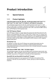
... utilizes the serial point-to ten times faster transfer rate than USB 2.0 and enables the iGPU function for Intel® integrated graphics performance. Chapter 1 ASUS SABERTOOTH Z97 MARK 2/USB 3.1 1-1 Intel® Z97 Express Chipset Intel® Z97 Express Chipset is the PCI Express bus standard that supports the ...allocation in the LGA1150 package. Quad-GPU SLI and Quad GPU CrossFireX™ Support This motherboard features the most powerful Intel® Z97 platform that features data transfer rates of DDR3 1866 / 1600 / 1333 MHz to boost the system's performance, and to PCIe...
... utilizes the serial point-to ten times faster transfer rate than USB 2.0 and enables the iGPU function for Intel® integrated graphics performance. Chapter 1 ASUS SABERTOOTH Z97 MARK 2/USB 3.1 1-1 Intel® Z97 Express Chipset Intel® Z97 Express Chipset is the PCI Express bus standard that supports the ...allocation in the LGA1150 package. Quad-GPU SLI and Quad GPU CrossFireX™ Support This motherboard features the most powerful Intel® Z97 platform that features data transfer rates of DDR3 1866 / 1600 / 1333 MHz to boost the system's performance, and to PCIe...
User Guide
Page 17
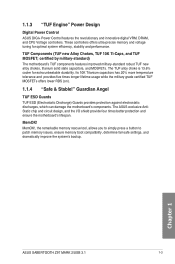
... AntiStatic chip and circuit design, and the I/O shield provide four times better protection and ensure the motherboard's lifespan. Chapter 1 ASUS SABERTOOTH Z97 MARK 2/USB 3.1 1-3 The TUF alloy choke is 13.6% cooler for optimal system efficiency, stability and performance. Guardian Angel TUF ESD Guards TUF... Guards provides protection against electrostatic discharges, which can damage the motherboard's components. 1.1.3 "TUF Engine" Power Design Digital Power Control ASUS DIGI+ Power Control features the revolutionary and innovative digital VRM, DRAM, and CPU Voltage controllers.
... AntiStatic chip and circuit design, and the I/O shield provide four times better protection and ensure the motherboard's lifespan. Chapter 1 ASUS SABERTOOTH Z97 MARK 2/USB 3.1 1-3 The TUF alloy choke is 13.6% cooler for optimal system efficiency, stability and performance. Guardian Angel TUF ESD Guards TUF... Guards provides protection against electrostatic discharges, which can damage the motherboard's components. 1.1.3 "TUF Engine" Power Design Digital Power Control ASUS DIGI+ Power Control features the revolutionary and innovative digital VRM, DRAM, and CPU Voltage controllers.
User Guide
Page 19
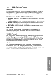
... Flashback button for about three seconds, and the UEFI BIOS is powered off, in sleep or hibernation mode. Chapter 1 ASUS SABERTOOTH Z97 MARK 2/USB 3.1 1-5 With ASUS Remote GO!, you to regularly check for your smart device. • File Transfer: Allows you to switch back and forth ... functions, with no need to supervise fan speed control, voltage and sensor readings. 1.1.6 ASUS Exclusive Features Remote GO! leads the way to a more , all your computer and smart device. USB Charger+ With a dedicated onboard controller, quick-charge all up to DLNA devices, remotely...
... Flashback button for about three seconds, and the UEFI BIOS is powered off, in sleep or hibernation mode. Chapter 1 ASUS SABERTOOTH Z97 MARK 2/USB 3.1 1-5 With ASUS Remote GO!, you to regularly check for your smart device. • File Transfer: Allows you to switch back and forth ... functions, with no need to supervise fan speed control, voltage and sensor readings. 1.1.6 ASUS Exclusive Features Remote GO! leads the way to a more , all your computer and smart device. USB Charger+ With a dedicated onboard controller, quick-charge all up to DLNA devices, remotely...
User Guide
Page 21
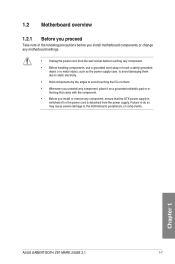
... came with the component. • Before you install motherboard components or change any motherboard settings. • Unplug the power cord from the power supply. Chapter 1 ASUS SABERTOOTH Z97 MARK 2/USB 3.1 1-7 Failure to do so may cause severe damage to avoid touching the ICs on them due to static electricity. • Hold components by the edges...
... came with the component. • Before you install motherboard components or change any motherboard settings. • Unplug the power cord from the power supply. Chapter 1 ASUS SABERTOOTH Z97 MARK 2/USB 3.1 1-7 Failure to do so may cause severe damage to avoid touching the ICs on them due to static electricity. • Hold components by the edges...
User Guide
Page 23
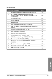
... TPM) Page 1-35 1-33 1-10 1-11 1-26 1-31 1-30 1-28 1-27 1-37 1-36 1-32 1-38 1-34 1-34 1-31 1-37 Chapter 1 ASUS SABERTOOTH Z97 MARK 2/USB 3.1 1-9 DDR3 DIMM slots 5. MemOK! USB 3.0 connector (20-1 pin USB3_12, USB3_34) 7. USB 2.0 connectors (10-1 pin USB1112, USB1314) 13. ATX power connectors (24-pin EATXPWR, 8-pin EATX12V) 2. Clear RTC RAM (3-pin CLRTC) 10. Thermal...
... TPM) Page 1-35 1-33 1-10 1-11 1-26 1-31 1-30 1-28 1-27 1-37 1-36 1-32 1-38 1-34 1-34 1-31 1-37 Chapter 1 ASUS SABERTOOTH Z97 MARK 2/USB 3.1 1-9 DDR3 DIMM slots 5. MemOK! USB 3.0 connector (20-1 pin USB3_12, USB3_34) 7. USB 2.0 connectors (10-1 pin USB1112, USB1314) 13. ATX power connectors (24-pin EATXPWR, 8-pin EATX12V) 2. Clear RTC RAM (3-pin CLRTC) 10. Thermal...
User Guide
Page 25
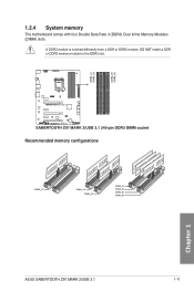
1.2.4 System memory The motherboard comes with four Double Data Rate 3 (DDR3) Dual Inline Memory Modules (DIMM) slots. Recommended memory configurations Chapter 1 ASUS SABERTOOTH Z97 MARK 2/USB 3.1 1-11 DO NOT install a DDR or DDR2 memory module to the DDR3 slot. A DDR3 module is notched differently from a DDR or DDR2 module.
1.2.4 System memory The motherboard comes with four Double Data Rate 3 (DDR3) Dual Inline Memory Modules (DIMM) slots. Recommended memory configurations Chapter 1 ASUS SABERTOOTH Z97 MARK 2/USB 3.1 1-11 DO NOT install a DDR or DDR2 memory module to the DDR3 slot. A DDR3 module is notched differently from a DDR or DDR2 module.
User Guide
Page 31
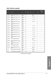
...; • • • • • • • • • • • • • • • • • • • (continued on the next page) Chapter 1 ASUS SABERTOOTH Z97 MARK 2/USB 3.1 1-17 Timing Voltage CMD16GX3M2A1866C9 (Ver5.29) (XMP) 16GB ( 2x DS 8GB ) CMD16GX3M4A1866C9 (Ver4.13) (XMP) 16GB ( 4x DS 4GB ) CMD16GX3M4A1866C9 (Ver8.16) (XMP) 16GB ( 4x...
...; • • • • • • • • • • • • • • • • • • • (continued on the next page) Chapter 1 ASUS SABERTOOTH Z97 MARK 2/USB 3.1 1-17 Timing Voltage CMD16GX3M2A1866C9 (Ver5.29) (XMP) 16GB ( 2x DS 8GB ) CMD16GX3M4A1866C9 (Ver4.13) (XMP) 16GB ( 4x DS 4GB ) CMD16GX3M4A1866C9 (Ver8.16) (XMP) 16GB ( 4x...
User Guide
Page 33
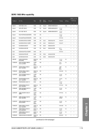
...- 1.5 10-27 9-9-9-24 1.5 1600-9- 1.5 9-9-24 10-10- 1.5 10-27 9-9-9-24 1.5 10-10- 1.5 10-27 10-10- 1.5 10-27 8-8-8-24 1.5 (continued on the next page) Chapter 1 ASUS SABERTOOTH Z97 MARK 2/USB 3.1 1-19 DDR3 1600 MHz capability Vendors Part No.
...- 1.5 10-27 9-9-9-24 1.5 1600-9- 1.5 9-9-24 10-10- 1.5 10-27 9-9-9-24 1.5 10-10- 1.5 10-27 10-10- 1.5 10-27 8-8-8-24 1.5 (continued on the next page) Chapter 1 ASUS SABERTOOTH Z97 MARK 2/USB 3.1 1-19 DDR3 1600 MHz capability Vendors Part No.
User Guide
Page 37
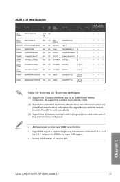
...• • • UMAX 84E48G93UM-13BPSYW 8GB DS UMAX U2S96D30TP-13 1333-9- 9-9-24 • • • Side(s): SS - Chapter 1 ASUS SABERTOOTH Z97 MARK 2/USB 3.1 1-23 Timing Voltage DIMM socket support (Optional) 1 2 4 Mach MXD3U133316GQ 16GB DS - - Double-sided DIMM support: (1) Supports one pair of ... install the modules into both the beige and brown slots as two pairs of Dual-channel memory configuration. • ASUS exclusively provides hyper DIMM support function. • Hyper DIMM support is subject to the physical characteristics of Dual-channel ...
...• • • UMAX 84E48G93UM-13BPSYW 8GB DS UMAX U2S96D30TP-13 1333-9- 9-9-24 • • • Side(s): SS - Chapter 1 ASUS SABERTOOTH Z97 MARK 2/USB 3.1 1-23 Timing Voltage DIMM socket support (Optional) 1 2 4 Mach MXD3U133316GQ 16GB DS - - Double-sided DIMM support: (1) Supports one pair of ... install the modules into both the beige and brown slots as two pairs of Dual-channel memory configuration. • ASUS exclusively provides hyper DIMM support function. • Hyper DIMM support is subject to the physical characteristics of Dual-channel ...
User Guide
Page 39
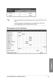
...- - shared - - - - - - shared - - shared - shared - - - - XHCI Controller - - - - - shared - - - - F G H - - - - - - - - - - - - - - - - - - - - - - - - - - - - - High Definition Audio - - - - - - shared - - - - shared - - - shared - - - - - - - Chapter 1 ASUS SABERTOOTH Z97 MARK 2/USB 3.1 1-25 shared - - - PCIe x16_3 Configuration x2 mode x4 mode PCI Express sharing mode PCIe x16_3 Rear USB 3.1_E1~E2 x2 Enabled x4 Disabled • We recommend that you provide sufficient power when...
...- - shared - - - - - - shared - - shared - shared - - - - XHCI Controller - - - - - shared - - - - F G H - - - - - - - - - - - - - - - - - - - - - - - - - - - - - High Definition Audio - - - - - - shared - - - - shared - - - shared - - - - - - - Chapter 1 ASUS SABERTOOTH Z97 MARK 2/USB 3.1 1-25 shared - - - PCIe x16_3 Configuration x2 mode x4 mode PCI Express sharing mode PCIe x16_3 Rear USB 3.1_E1~E2 x2 Enabled x4 Disabled • We recommend that you provide sufficient power when...
User Guide
Page 41
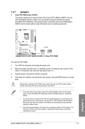
... onboard battery and move the cap back to enable C.P.R. function. Move the jumper cap from pins 1-2 (default) to overclocking, use the C.P.R. (CPU Parameter Recall) feature. ASUS SABERTOOTH Z97 MARK 2/USB 3.1 1-27 Chapter 1 Plug the power cord and turn off is required to pins 1-2. 3. You must turn ON the computer. 4. Clear RTC RAM (3-pin CLRTC) This...
... onboard battery and move the cap back to enable C.P.R. function. Move the jumper cap from pins 1-2 (default) to overclocking, use the C.P.R. (CPU Parameter Recall) feature. ASUS SABERTOOTH Z97 MARK 2/USB 3.1 1-27 Chapter 1 Plug the power cord and turn off is required to pins 1-2. 3. You must turn ON the computer. 4. Clear RTC RAM (3-pin CLRTC) This...
User Guide
Page 43
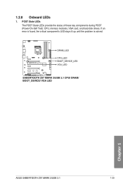
Chapter 1 ASUS SABERTOOTH Z97 MARK 2/USB 3.1 1-29 POST State LEDs The POST State LEDs provide the status of these key components during POST (Power-On-Self Test): CPU, memory modules, VGA card, and hard disk drives. If an error is found, the critical component's LED stays lit up until the problem is solved. 1.2.8 Onboard LEDs 1.
Chapter 1 ASUS SABERTOOTH Z97 MARK 2/USB 3.1 1-29 POST State LEDs The POST State LEDs provide the status of these key components during POST (Power-On-Self Test): CPU, memory modules, VGA card, and hard disk drives. If an error is found, the critical component's LED stays lit up until the problem is solved. 1.2.8 Onboard LEDs 1.
User Guide
Page 45
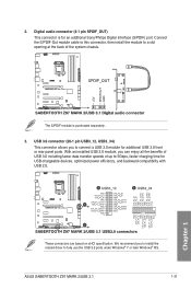
... (20-1 pin USB3_12, USB3_34) This connector allows you to connect a USB 3.0 module for USB-chargeable devices, optimized power efficiency, and backward compatibility with USB 2.0. ASUS SABERTOOTH Z97 MARK 2/USB 3.1 1-31 Chapter 1 The S/PDIF module is for an additional Sony/Philips Digital Interface (S/PDIF) port. With an installed USB 3.0 module, you to install the related driver to 5Gbps, faster charging...
... (20-1 pin USB3_12, USB3_34) This connector allows you to connect a USB 3.0 module for USB-chargeable devices, optimized power efficiency, and backward compatibility with USB 2.0. ASUS SABERTOOTH Z97 MARK 2/USB 3.1 1-31 Chapter 1 The S/PDIF module is for an additional Sony/Philips Digital Interface (S/PDIF) port. With an installed USB 3.0 module, you to install the related driver to 5Gbps, faster charging...
User Guide
Page 47
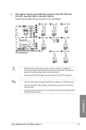
... to the fan connectors. Do not place jumper caps on the motherboard. • DO NOT forget to connect the fan cables to the ASST_FAN connectors. ASUS SABERTOOTH Z97 MARK 2/USB 3.1 1-33 Chapter 1 5.
... to the fan connectors. Do not place jumper caps on the motherboard. • DO NOT forget to connect the fan cables to the ASST_FAN connectors. ASUS SABERTOOTH Z97 MARK 2/USB 3.1 1-33 Chapter 1 5.
User Guide
Page 49
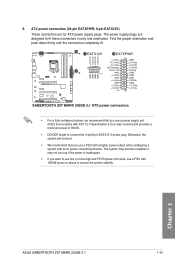
... up if the power is inadequate. • If you use a PSU with 1000W power or above to fit these connectors in only one orientation. Chapter 1 ASUS SABERTOOTH Z97 MARK 2/USB 3.1 1-35
... up if the power is inadequate. • If you use a PSU with 1000W power or above to fit these connectors in only one orientation. Chapter 1 ASUS SABERTOOTH Z97 MARK 2/USB 3.1 1-35
User Guide
Page 51
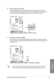
DirectKey connector (2-pin DRCT) This connector is for details. ASUS SABERTOOTH Z97 MARK 2/USB 3.1 1-37 Connect the button cable that supports the DirectKey function. TPM connector (20-1 pin TPM) This connector supports a Trusted Platform Module (TPM) system, which securely ...
DirectKey connector (2-pin DRCT) This connector is for details. ASUS SABERTOOTH Z97 MARK 2/USB 3.1 1-37 Connect the button cable that supports the DirectKey function. TPM connector (20-1 pin TPM) This connector supports a Trusted Platform Module (TPM) system, which securely ...
User Guide
Page 53
ASUS SABERTOOTH Z97 MARK 2/USB 3.1 1-39 Chapter 1
ASUS SABERTOOTH Z97 MARK 2/USB 3.1 1-39 Chapter 1
User Guide
Page 54
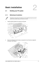
The motherboard layout may vary with models, but the installation steps are for all models. 1. Chapter 2 ASUS SABERTOOTH Z97 MARK 2/USB 3.1 2-1 Chapter 2: Basic installation Basic installation 2.1 Building your PC system 2 2.1.1 Motherboard installation The diagrams in this section are the same for reference only. Place the motherboard into the chassis, ensuring that its rear I/O ports are aligned to the chassis rear I /O panel. Install the ASUS Q-Shield to the chassis' rear I /O panel. 2.
The motherboard layout may vary with models, but the installation steps are for all models. 1. Chapter 2 ASUS SABERTOOTH Z97 MARK 2/USB 3.1 2-1 Chapter 2: Basic installation Basic installation 2.1 Building your PC system 2 2.1.1 Motherboard installation The diagrams in this section are the same for reference only. Place the motherboard into the chassis, ensuring that its rear I/O ports are aligned to the chassis rear I /O panel. Install the ASUS Q-Shield to the chassis' rear I /O panel. 2.
User Guide
Page 56
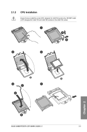
DO NOT install a CPU designed for LGA1150 socket only. Chapter 2 ASUS SABERTOOTH Z97 MARK 2/USB 3.1 2-3 2.1.2 CPU installation Ensure that you install the correct CPU designed for LGA1155 and LGA1156 sockets on the LGA1150 socket.
DO NOT install a CPU designed for LGA1150 socket only. Chapter 2 ASUS SABERTOOTH Z97 MARK 2/USB 3.1 2-3 2.1.2 CPU installation Ensure that you install the correct CPU designed for LGA1155 and LGA1156 sockets on the LGA1150 socket.


