
Installation Guide
Page 3
Contents Contents...3 Package contents...4 Installing the assistant fans 5 Installing the Dust Defenders 7 Installing the DIMM slot covers 7 Installing the PCIe x16 and PCIe x1 slot covers 7 Installing the onboard connector caps 7 Installing the back I/O caps 8 Installing the back I/O dust filter 8 Installing the Thermistor cable 9 Contact Information 10 3
Contents Contents...3 Package contents...4 Installing the assistant fans 5 Installing the Dust Defenders 7 Installing the DIMM slot covers 7 Installing the PCIe x16 and PCIe x1 slot covers 7 Installing the onboard connector caps 7 Installing the back I/O caps 8 Installing the back I/O dust filter 8 Installing the Thermistor cable 9 Contact Information 10 3
Installation Guide
Page 4
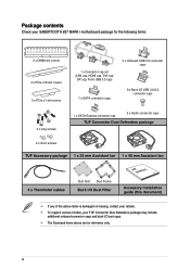
Package contents Check your SABERTOOTH Z97 MARK I motherboard package for the following items: 2 x DIMM slot covers 3 x PCIe x16 slot covers 3 x PCIe x1 slot covers 4 x long screws 1 x Connector cap set (LAN cap, HDMI ... Defenders package 2 x short screws TUF Accessory package 1 x 35 mm Assistant fan 1 x 40 mm Assistant fan 3 x Thermistor cables Dust Grid Dust Frame Back I/O Dust Filter Accessory installation guide (this document) • If any of the above items is damaged or missing, contact your retailer. • To support various models, your TUF Connector...
Package contents Check your SABERTOOTH Z97 MARK I motherboard package for the following items: 2 x DIMM slot covers 3 x PCIe x16 slot covers 3 x PCIe x1 slot covers 4 x long screws 1 x Connector cap set (LAN cap, HDMI ... Defenders package 2 x short screws TUF Accessory package 1 x 35 mm Assistant fan 1 x 40 mm Assistant fan 3 x Thermistor cables Dust Grid Dust Frame Back I/O Dust Filter Accessory installation guide (this document) • If any of the above items is damaged or missing, contact your retailer. • To support various models, your TUF Connector...
Installation Guide
Page 5
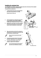
...'s behaviour. Match the two screw holes on the 40 mm assistant fan with the two screw holes on the back I/O (A) then remove the back I /O shield. 3. Installing the assistant fans The SABERTOOTH Z97 MARK I motherboard package comes with a 35 mm and a 40 mm assistant fans for later use. 2. To...
...'s behaviour. Match the two screw holes on the 40 mm assistant fan with the two screw holes on the back I/O (A) then remove the back I /O shield. 3. Installing the assistant fans The SABERTOOTH Z97 MARK I motherboard package comes with a 35 mm and a 40 mm assistant fans for later use. 2. To...
Installation Guide
Page 6
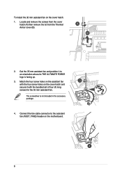
... is facing up. 3. Connect the fan cable connector to an orientation where its THE ULTIMATE FORCE logo is not included in the accessory package. 4. To install the 35 mm assistant fan on the motherboard. 6 Get the 35 mm assistant fan and position it with the bundled set of four (4) long screws...
... is facing up. 3. Connect the fan cable connector to an orientation where its THE ULTIMATE FORCE logo is not included in the accessory package. 4. To install the 35 mm assistant fan on the motherboard. 6 Get the 35 mm assistant fan and position it with the bundled set of four (4) long screws...
Installation Guide
Page 7
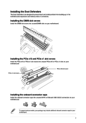
... are designed to prevent dust and small particles from building up in the motherboard's expansion and memory slots or connectors. Installing the DIMM slot covers Install the DIMM slot covers into unused DIMM slots on your motherboard. 7 To support various models, your package may include ...additional onboard connector caps for your motherboard. Installing the PCIe x16 and PCIe x1 slot covers Install the PCIe x16 or PCIe x1 slot covers into unused SATA or Onboard USB 3.0/2.0 connectors on your motherboard. ...
... are designed to prevent dust and small particles from building up in the motherboard's expansion and memory slots or connectors. Installing the DIMM slot covers Install the DIMM slot covers into unused DIMM slots on your motherboard. 7 To support various models, your package may include ...additional onboard connector caps for your motherboard. Installing the PCIe x16 and PCIe x1 slot covers Install the PCIe x16 or PCIe x1 slot covers into unused SATA or Onboard USB 3.0/2.0 connectors on your motherboard. ...
Installation Guide
Page 8
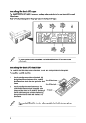
Refer to fasten the back I/O dust grid into the system To install the back I /O dust grid 2. Installing the back I/O dust filter The back I/O dust filter helps reduce the intake of dust and small particles into the I/O shield with the back I/O ... proper placement of the back I/O dust frame then attach the dust grid to the dust Back I/O dust frame frame. Clean your motherboard. Installing the back I/O caps The SABERTOOTH Z97 MARK I accessory package takes protection to ensure optimum airflow. 8 Match and align seven holes of the back I/O dust grid and seven fasteners of...
Refer to fasten the back I/O dust grid into the system To install the back I /O dust grid 2. Installing the back I/O dust filter The back I/O dust filter helps reduce the intake of dust and small particles into the I/O shield with the back I/O ... proper placement of the back I/O dust frame then attach the dust grid to the dust Back I/O dust frame frame. Clean your motherboard. Installing the back I/O caps The SABERTOOTH Z97 MARK I accessory package takes protection to ensure optimum airflow. 8 Match and align seven holes of the back I/O dust grid and seven fasteners of...
Installation Guide
Page 9
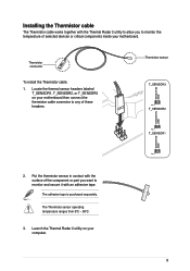
...the Thermal Radar 2 utility on your motherboard then connect the thermistor cable connector to monitor the temperature of these headers. Thermistor sensor 2. Thermistor connector To install the Thermistor cable: 1. The Thermistor sensor operating temperature ranges from 0oC - 80oC. 3. Put the thermistor sensor in contact with the surface of the ... monitor and secure it with the Thermal Radar 2 utility to allow you to any of selected devices or critical components inside your computer. 9 Installing the Thermistor cable The Thermistor cable works together with an adhesive tape.
...the Thermal Radar 2 utility on your motherboard then connect the thermistor cable connector to monitor the temperature of these headers. Thermistor sensor 2. Thermistor connector To install the Thermistor cable: 1. The Thermistor sensor operating temperature ranges from 0oC - 80oC. 3. Put the thermistor sensor in contact with the surface of the ... monitor and secure it with the Thermal Radar 2 utility to allow you to any of selected devices or critical components inside your computer. 9 Installing the Thermistor cable The Thermistor cable works together with an adhesive tape.


