
User Guide
Page 2
SPECIFICATIONS AND INFORMATION CONTAINED IN THIS MANUAL ARE FURNISHED FOR INFORMATIONAL USE ONLY, AND ARE SUBJECT TO CHANGE AT ANY TIME WITHOUT NOTICE, AND SHOULD NOT BE CONSTRUED AS A COMMITMENT BY ASUS. This offer is authorized in this information. ii Product warranty or service ... complete source code as the corresponding binary/object code. or (2) the serial number of this product is licensed under the General Public License ("GPL"), under various Free Open Source Software licenses. ASUS PROVIDES THIS MANUAL "AS IS" WITHOUT WARRANTY OF ANY KIND, EITHER EXPRESS OR IMPLIED,...
SPECIFICATIONS AND INFORMATION CONTAINED IN THIS MANUAL ARE FURNISHED FOR INFORMATIONAL USE ONLY, AND ARE SUBJECT TO CHANGE AT ANY TIME WITHOUT NOTICE, AND SHOULD NOT BE CONSTRUED AS A COMMITMENT BY ASUS. This offer is authorized in this information. ii Product warranty or service ... complete source code as the corresponding binary/object code. or (2) the serial number of this product is licensed under the General Public License ("GPL"), under various Free Open Source Software licenses. ASUS PROVIDES THIS MANUAL "AS IS" WITHOUT WARRANTY OF ANY KIND, EITHER EXPRESS OR IMPLIED,...

User Guide
Page 4
...3.6.1 AMD fTPM Configuration 3-13 3.6.2 CPU Configuration 3-13 3.6.3 NB Configuration 3-14 3.6.4 SATA Configuration 3-14 3.6.5 Onboard Devices Configuration 3-15 3.6.6 APM Configuration 3-16 3.6.7 Network Stack Configuration 3-16 3.6.8 HDD/SSD SMART Information 3-16 3.6.9 USB Configuration 3-16 3.7 Monitor menu 3-17 3.8 Boot menu 3-17 3.9 Tool menu 3-19 3.9.1 ASUS EZ Flash 3 Utility 3-19 3.9.2 Secure Erase 3-19 3.9.3 ASUS Overclocking Profile 3-20 3.9.4 ASUS SPD Information 3-20 3.9.5 Graphics Card Information 3-20 3.10 Exit menu 3-21 3.11 Updating BIOS 3-21 3.11.1 EZ Update...
...3.6.1 AMD fTPM Configuration 3-13 3.6.2 CPU Configuration 3-13 3.6.3 NB Configuration 3-14 3.6.4 SATA Configuration 3-14 3.6.5 Onboard Devices Configuration 3-15 3.6.6 APM Configuration 3-16 3.6.7 Network Stack Configuration 3-16 3.6.8 HDD/SSD SMART Information 3-16 3.6.9 USB Configuration 3-16 3.7 Monitor menu 3-17 3.8 Boot menu 3-17 3.9 Tool menu 3-19 3.9.1 ASUS EZ Flash 3 Utility 3-19 3.9.2 Secure Erase 3-19 3.9.3 ASUS Overclocking Profile 3-20 3.9.4 ASUS SPD Information 3-20 3.9.5 Graphics Card Information 3-20 3.10 Exit menu 3-21 3.11 Updating BIOS 3-21 3.11.1 EZ Update...

User Guide
Page 10
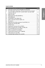
...x4 and SATA modes) 1 x 4-Pin CPU fan connector 1 x 4-Pin CPU_OPT fan connector 1 x 4-Pin AIO_PUMP connector 1 x 4-Pin W_PUMP+ connector 3 x 4-Pin Chassis fan connectors 1 x Thermal sensor connector 2 x RGB headers 1 x 24-pin EATX power connector 1 x 8-pin EATX 12V power connector 1 x System panel connector 1 x Front panel audio connector (AAFP) 1 x Clear CMOS jumper (2-pin) (continued on LAN, Audio, KBMS and USB3.0/2.0 ports - Q-Slot - ROG STRIX X370-F GAMING specifications summary Special Features Back I/O Ports Internal I /O ASUS Exclusive Features - Q-LED (CPU, DRAM, VGA, Boot Device LED...
...x4 and SATA modes) 1 x 4-Pin CPU fan connector 1 x 4-Pin CPU_OPT fan connector 1 x 4-Pin AIO_PUMP connector 1 x 4-Pin W_PUMP+ connector 3 x 4-Pin Chassis fan connectors 1 x Thermal sensor connector 2 x RGB headers 1 x 24-pin EATX power connector 1 x 8-pin EATX 12V power connector 1 x System panel connector 1 x Front panel audio connector (AAFP) 1 x Clear CMOS jumper (2-pin) (continued on LAN, Audio, KBMS and USB3.0/2.0 ports - Q-Slot - ROG STRIX X370-F GAMING specifications summary Special Features Back I/O Ports Internal I /O ASUS Exclusive Features - Q-LED (CPU, DRAM, VGA, Boot Device LED...
User Guide
Page 15
...AMD Serial ATA 6.0 Gb/s connectors (7-pin SATA6G_1-8) 10. USB 3.0 connectors (20-1 pin USB3_78, USB3_910) 14. Front panel audio connector (10-1 pin AAFP) Page 1-16 1-15 1-4 1-17 1-4 1-8 1-12 1-18 1-11 1-8 2-11 1-14 1-12 1-9 1-13 1-13 1-10 1-10 ASUS ROG STRIX X370-F GAMING 1-3 Chapter 1 Layout contents Connectors/Jumpers/Buttons and switches/Slots 1. DDR4 DIMM slots 6. M.2 Socket 3 9. Clear RTC RAM jumper (2-pin CLRTC) 15. RGB headers (4-pin RGB_HEADER1-2) 5. Standby power LED (SB_PWR) 11. 3D Mount holes 12. USB 2.0 connector (10-1 pin USB34) 16. Q LEDs (BOOT, VGA, DRAM, CPU...
...AMD Serial ATA 6.0 Gb/s connectors (7-pin SATA6G_1-8) 10. USB 3.0 connectors (20-1 pin USB3_78, USB3_910) 14. Front panel audio connector (10-1 pin AAFP) Page 1-16 1-15 1-4 1-17 1-4 1-8 1-12 1-18 1-11 1-8 2-11 1-14 1-12 1-9 1-13 1-13 1-10 1-10 ASUS ROG STRIX X370-F GAMING 1-3 Chapter 1 Layout contents Connectors/Jumpers/Buttons and switches/Slots 1. DDR4 DIMM slots 6. M.2 Socket 3 9. Clear RTC RAM jumper (2-pin CLRTC) 15. RGB headers (4-pin RGB_HEADER1-2) 5. Standby power LED (SB_PWR) 11. 3D Mount holes 12. USB 2.0 connector (10-1 pin USB34) 16. Q LEDs (BOOT, VGA, DRAM, CPU...
User Guide
Page 17
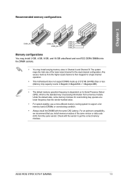
... the DIMM sockets. • You may operate at a lower frequency than the vendor-marked value. • For system stability, use a more efficient memory cooling system to support a full memory load (4 DIMMs) or overclocking condition. • Always install the DIMMS with the vendor to get the correct memory modules. ASUS ROG STRIX X370-F GAMING 1-5 Any excess memory from the higher-sized channel is the standard way of accessing information from...
... the DIMM sockets. • You may operate at a lower frequency than the vendor-marked value. • For system stability, use a more efficient memory cooling system to support a full memory load (4 DIMMs) or overclocking condition. • Always install the DIMMS with the vendor to get the correct memory modules. ASUS ROG STRIX X370-F GAMING 1-5 Any excess memory from the higher-sized channel is the standard way of accessing information from...
User Guide
Page 19
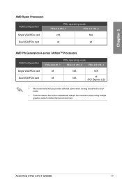
... Chapter 1 AMD Ryzen Processors VGA Configuration Single VGA/PCIe card Dual VGA/PCIe card PCIe operating mode PCIe 3.0 x16_1 PCIe 3.0 x16_2 x16 N/A x8 x8 AMD 7th Generation A-series / Athlon™ Processors VGA Configuration Single VGA/PCIe card Dual VGA/PCIe card PCIe operating mode PCIe 3.0 x16_1 PCIe 3.0 x16_2 PCIe 2.0 x16_3 x8 N/A N/A x8 N/A x4 (PCI Express 2.0) • We recommend that you provide sufficient power when running CrossFireX or SLI® mode. • Connect chassis fans to the motherboard chassis fan connectors when using multiple graphics cards for...
... Chapter 1 AMD Ryzen Processors VGA Configuration Single VGA/PCIe card Dual VGA/PCIe card PCIe operating mode PCIe 3.0 x16_1 PCIe 3.0 x16_2 x16 N/A x8 x8 AMD 7th Generation A-series / Athlon™ Processors VGA Configuration Single VGA/PCIe card Dual VGA/PCIe card PCIe operating mode PCIe 3.0 x16_1 PCIe 3.0 x16_2 PCIe 2.0 x16_3 x8 N/A N/A x8 N/A x4 (PCI Express 2.0) • We recommend that you provide sufficient power when running CrossFireX or SLI® mode. • Connect chassis fans to the motherboard chassis fan connectors when using multiple graphics cards for...
User Guide
Page 21
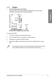
... system passwords. Hold down the key during the boot process and enter BIOS setup to clear the CMOS RTC RAM data. After clearing the CMOS, reinstall the battery. strix x370-F GAMING CLRTC PIN 1 STRIX X370-F GAMING Clear RTC RAM To erase the RTC RAM: 1. Turn OFF the computer and unplug the power cord. 2. If the steps above do not help, remove the onboard battery and short the two pins again to re-enter data. Plug the power cord and turn ON the computer. 4. ASUS ROG STRIX X370-F GAMING 1-9
... system passwords. Hold down the key during the boot process and enter BIOS setup to clear the CMOS RTC RAM data. After clearing the CMOS, reinstall the battery. strix x370-F GAMING CLRTC PIN 1 STRIX X370-F GAMING Clear RTC RAM To erase the RTC RAM: 1. Turn OFF the computer and unplug the power cord. 2. If the steps above do not help, remove the onboard battery and short the two pins again to re-enter data. Plug the power cord and turn ON the computer. 4. ASUS ROG STRIX X370-F GAMING 1-9
User Guide
Page 23
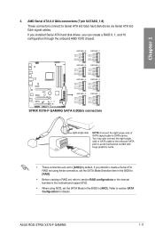
...drives via Serial ATA 6.0 Gb/s signal cables. ASUS ROG STRIX X370-F GAMING 1-11 If you can create a RAID 0, 1, and 10 configuration through the onboard AMD X370 chipset. AMD Serial ATA 6.0 Gb/s connectors (7-pin SATA6G_1-8) These connectors connect to section SATA Configuration for details. If you installed Serial ATA hard disk drives, you intend to create a Serial ATA RAID set using these connectors, set the SATA Mode Selection item in the BIOS to [RAID]. • Before creating a RAID set, refer to section RAID configurations or the manual bundled in the motherboard support DVD...
...drives via Serial ATA 6.0 Gb/s signal cables. ASUS ROG STRIX X370-F GAMING 1-11 If you can create a RAID 0, 1, and 10 configuration through the onboard AMD X370 chipset. AMD Serial ATA 6.0 Gb/s connectors (7-pin SATA6G_1-8) These connectors connect to section SATA Configuration for details. If you installed Serial ATA hard disk drives, you intend to create a Serial ATA RAID set using these connectors, set the SATA Mode Selection item in the BIOS to [RAID]. • Before creating a RAID set, refer to section RAID configurations or the manual bundled in the motherboard support DVD...

User Guide
Page 25
... cable to 480 Mb/s connection speed. Doing so will damage the motherboard! 7. This USB connector complies with USB 2.0 specification that allows you to a slot opening at the back of your motherboard's critical components and connected devices. strix x370-F GAMING T_SENSOR GND PIN 1 SENSOR IN STRIX X370-F GAMING Thermal sensor connector ASUS ROG STRIX X370-F GAMING 1-13 Connect the USB module cable to this connector, then install the module to monitor the temperature of the system chassis. Chapter 1 6. USB 2.0 connector (10-1 pin USB34) This connector is for a USB 2.0 port...
... cable to 480 Mb/s connection speed. Doing so will damage the motherboard! 7. This USB connector complies with USB 2.0 specification that allows you to a slot opening at the back of your motherboard's critical components and connected devices. strix x370-F GAMING T_SENSOR GND PIN 1 SENSOR IN STRIX X370-F GAMING Thermal sensor connector ASUS ROG STRIX X370-F GAMING 1-13 Connect the USB module cable to this connector, then install the module to monitor the temperature of the system chassis. Chapter 1 6. USB 2.0 connector (10-1 pin USB34) This connector is for a USB 2.0 port...

User Guide
Page 27
..., and chassis fan connectors (4-pin CPU_FAN; 4-pin CPU_OPT; 4-pin W_PUMP+; 4-pin AIO_PUMP; 4-pin CHA_FAN1-3) Connect the fan cables to the fan connectors on water cooling device. These are not jumpers! Header CPU_FAN CPU_OPT CHA_FAN1 CHA_FAN2 CHA_FAN3 AIO_PUMP W_PUMP+ Max. Current 1A 1A 1A 1A 1A 1A 3A Max. Power 12W 12W 12W 12W 12W 12W 36W Default Speed Q-Fan Controlled Q-Fan Controlled Q-Fan Controlled Q-Fan Controlled Q-Fan Controlled Full Speed Full Speed Shared Control A A B B ASUS ROG STRIX X370-F GAMING 1-15 W_PUMP+ function support depends on the motherboard, ensuring...
..., and chassis fan connectors (4-pin CPU_FAN; 4-pin CPU_OPT; 4-pin W_PUMP+; 4-pin AIO_PUMP; 4-pin CHA_FAN1-3) Connect the fan cables to the fan connectors on water cooling device. These are not jumpers! Header CPU_FAN CPU_OPT CHA_FAN1 CHA_FAN2 CHA_FAN3 AIO_PUMP W_PUMP+ Max. Current 1A 1A 1A 1A 1A 1A 3A Max. Power 12W 12W 12W 12W 12W 12W 36W Default Speed Q-Fan Controlled Q-Fan Controlled Q-Fan Controlled Q-Fan Controlled Q-Fan Controlled Full Speed Full Speed Shared Control A A B B ASUS ROG STRIX X370-F GAMING 1-15 W_PUMP+ function support depends on the motherboard, ensuring...
User Guide
Page 33
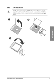
DO NOT force the CPU into the socket to prevent bending the connectors on the socket and damaging the CPU! 1 2 3 Chapter 2 ASUS ROG STRIX X370-F GAMING 2-3 The CPU fits in only one correct orientation. 2.1.2 CPU installation The AMD AM4 socket is compatible with AMD AM4 processors. Ensure you use a CPU designed for the AM4 socket.
DO NOT force the CPU into the socket to prevent bending the connectors on the socket and damaging the CPU! 1 2 3 Chapter 2 ASUS ROG STRIX X370-F GAMING 2-3 The CPU fits in only one correct orientation. 2.1.2 CPU installation The AMD AM4 socket is compatible with AMD AM4 processors. Ensure you use a CPU designed for the AM4 socket.
User Guide
Page 47
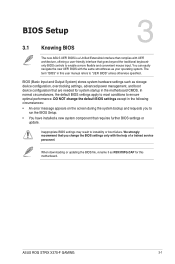
... UEFI BIOS with the help of a trained service personnel. In normal circumstances, the default BIOS settings apply to most conditions to instability or boot failure. Inappropriate BIOS settings may result to ensure optimal performance. When downloading or updating the BIOS file, rename it as your operating system. Chapter 3 ASUS ROG STRIX X370-F GAMING 3-1 DO NOT change the BIOS settings only with the same smoothness as RSX370FG.CAP for system startup in the motherboard CMOS...
... UEFI BIOS with the help of a trained service personnel. In normal circumstances, the default BIOS settings apply to most conditions to instability or boot failure. Inappropriate BIOS settings may result to ensure optimal performance. When downloading or updating the BIOS file, rename it as your operating system. Chapter 3 ASUS ROG STRIX X370-F GAMING 3-1 DO NOT change the BIOS settings only with the same smoothness as RSX370FG.CAP for system startup in the motherboard CMOS...

User Guide
Page 51
... display a list of options. A configurable field is highlighted when selected. To change the value of a field, select it to select items in BIOS Setup. Use key to capture the BIOS screen and save it and press to display the other items on the right side of the ASUS support website. Chapter 3 ASUS ROG STRIX X370-F GAMING 3-5 You cannot select an item that do not fit on your mobile device to connect...
... display a list of options. A configurable field is highlighted when selected. To change the value of a field, select it to select items in BIOS Setup. Use key to capture the BIOS screen and save it and press to display the other items on the right side of the ASUS support website. Chapter 3 ASUS ROG STRIX X370-F GAMING 3-5 You cannot select an item that do not fit on your mobile device to connect...

User Guide
Page 60
...Internal Graphics Device Multi-Monitor support for ASUS Hyper Kit card. Configuration options: [IGFX Video] [PCIE Video] UMA Frame Buffer Size [Auto] Configuration options: [Auto] [32M] [64M] [128M] [256M] [512M] [1G] [2G] 3.6.4 SATA Configuration While entering Setup, the BIOS automatically detects the presence of Internal Graphics Device will keep memory reserved. Configuration options: [Disabled] [Enabled] SATA Mode This item allows you to set the SATA configuration. [AHCI] [RAID] Set to [AHCI] when you to the corresponding SATA port. The AHCI allows the onboard storage driver...
...Internal Graphics Device Multi-Monitor support for ASUS Hyper Kit card. Configuration options: [IGFX Video] [PCIE Video] UMA Frame Buffer Size [Auto] Configuration options: [Auto] [32M] [64M] [128M] [256M] [512M] [1G] [2G] 3.6.4 SATA Configuration While entering Setup, the BIOS automatically detects the presence of Internal Graphics Device will keep memory reserved. Configuration options: [Disabled] [Enabled] SATA Mode This item allows you to set the SATA configuration. [AHCI] [RAID] Set to [AHCI] when you to the corresponding SATA port. The AHCI allows the onboard storage driver...

User Guide
Page 61
... use the Azalia High Definition Audio Controller Configuration options: [Disabled] [Enabled] PCIEX16_3 4X-2X Switch This item allows you to enable/disable SATA Hot Plug Support. In Sleep, hibernate and soft off states [On] LEDs will light up in Power State S5 This item allows you to switch between PCIe Lanes and configure onboard devices. Configuration options: [On] [Off] Charging USB devices in S3(sleep), S4(hibernate) and S5(soft off)states. [Off] LEDs will run at X4 mode for high...
... use the Azalia High Definition Audio Controller Configuration options: [Disabled] [Enabled] PCIEX16_3 4X-2X Switch This item allows you to enable/disable SATA Hot Plug Support. In Sleep, hibernate and soft off states [On] LEDs will light up in Power State S5 This item allows you to switch between PCIe Lanes and configure onboard devices. Configuration options: [On] [Off] Charging USB devices in S3(sleep), S4(hibernate) and S5(soft off)states. [Off] LEDs will run at X4 mode for high...

User Guide
Page 62
... enabled, you to enable or disable the UEFI network stack 3.6.8 HDD/SSD SMART Information This menu displays the SMART information of the USB ports. If no USB device is detected, the item shows None. When set system wake and sleep settings. The Mass Storage Devices item shows the auto-detected values. USB Single Port Control This item allows you to set to [Enabled], all other installed PCI-E LAN cards. 3.6.6 APM Configuration The items in this menu allow you to enable or disable the individual USB ports...
... enabled, you to enable or disable the UEFI network stack 3.6.8 HDD/SSD SMART Information This menu displays the SMART information of the USB ports. If no USB device is detected, the item shows None. When set system wake and sleep settings. The Mass Storage Devices item shows the auto-detected values. USB Single Port Control This item allows you to set to [Enabled], all other installed PCI-E LAN cards. 3.6.6 APM Configuration The items in this menu allow you to enable or disable the individual USB ports...

User Guide
Page 63
... its normal boot speed. Chapter 3 ASUS ROG STRIX X370-F GAMING 3-17 Next Boot after AC Power Loss [Normal Boot] Returns to normal boot on the next boot after POST. CSM (Compatibility Support Module) This item allows you to configure the CSM (Compatibility Support Module) items to fully support the various VGA, bootable devices and add-on devices for each fan. 3.8 Boot menu The Boot menu items allow you to fully support the Windows® the Windows secure update and secure boot. The...
... its normal boot speed. Chapter 3 ASUS ROG STRIX X370-F GAMING 3-17 Next Boot after AC Power Loss [Normal Boot] Returns to normal boot on the next boot after POST. CSM (Compatibility Support Module) This item allows you to configure the CSM (Compatibility Support Module) items to fully support the various VGA, bootable devices and add-on devices for each fan. 3.8 Boot menu The Boot menu items allow you to fully support the Windows® the Windows secure update and secure boot. The...

User Guide
Page 66
... graphics card installed in the BIOS Flash. Load/Save Profile from/to USB Drive This item allows you to load or save profile from the same memory/ CPU configuration and BIOS version. You have password protection by ASUS. Key in a profile number from Profile This item allows you to load the previous BIOS settings saved in your PC must be locked if the Secure Erase process is frozen, a power off or hard reset...
... graphics card installed in the BIOS Flash. Load/Save Profile from/to USB Drive This item allows you to load or save profile from the same memory/ CPU configuration and BIOS version. You have password protection by ASUS. Key in a profile number from Profile This item allows you to load the previous BIOS settings saved in your PC must be locked if the Secure Erase process is frozen, a power off or hard reset...

User Guide
Page 70
... or reset the system while updating the BIOS! The BIOS file in the motherboard support DVD may be older than the BIOS file published on the system. 2. Insert the motherboard support DVD to the optical drive, or the USB flash drive containing the BIOS file to recover the BIOS setting. The system requires you want to a USB flash drive. Chapter 3 3-24 Chapter 3: BIOS Setup You can cause system boot failure! If you to enter BIOS Setup to the USB port. 3. Turn on the ASUS official...
... or reset the system while updating the BIOS! The BIOS file in the motherboard support DVD may be older than the BIOS file published on the system. 2. Insert the motherboard support DVD to the optical drive, or the USB flash drive containing the BIOS file to recover the BIOS setting. The system requires you want to a USB flash drive. Chapter 3 3-24 Chapter 3: BIOS Setup You can cause system boot failure! If you to enter BIOS Setup to the USB port. 3. Turn on the ASUS official...

User Guide
Page 72
... model and capacity when creating a disk array. 4.1.2 Installing Serial ATA hard disks The motherboard supports Serial ATA hard disk drives. Connect a SATA power cable to load the UEFI driver for the corresponding OS version. Insert the support USB drive with RAID driver into the drive bays. 2. To set up a Windows® UEFI operating system under RAID mode, ensure to the power connector on each drive. 4.2 Creating a RAID driver disk 4.2.1 Creating a RAID driver disk in Windows® To install the RAID driver for a RAID configuration: 1. Follow the succeeding screen instructions...
... model and capacity when creating a disk array. 4.1.2 Installing Serial ATA hard disks The motherboard supports Serial ATA hard disk drives. Connect a SATA power cable to load the UEFI driver for the corresponding OS version. Insert the support USB drive with RAID driver into the drive bays. 2. To set up a Windows® UEFI operating system under RAID mode, ensure to the power connector on each drive. 4.2 Creating a RAID driver disk 4.2.1 Creating a RAID driver disk in Windows® To install the RAID driver for a RAID configuration: 1. Follow the succeeding screen instructions...


