User Guide
Page 12
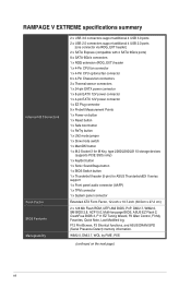
...2260/2280/22110 storage devices (supports PCIE SSDs only) 1 x KeyBot button 1 x Sonic SoundStage button 1 x BIOS Switch button 1 x Thunderbolt header (5-pin) for ASUS ThunderboldEX II series support 1 x Front panel audio connector (AAFP) 1 x TPM connector 1 x System panel connector Extended ATX Form Factor, 12...functions, and ASUS DRAM SPD (Serial Presence Detect) memory information. WfM2.0, DMI2.7, WOL by PME, PXE (continued on button 1 x Reset button 1 x Safe boot button 1 x ReTry button 1 x LN2 mode jumper 1 x Slow mode switch 1 x MemOK! RAMPAGE V EXTREME specifications summary Internal...
...2260/2280/22110 storage devices (supports PCIE SSDs only) 1 x KeyBot button 1 x Sonic SoundStage button 1 x BIOS Switch button 1 x Thunderbolt header (5-pin) for ASUS ThunderboldEX II series support 1 x Front panel audio connector (AAFP) 1 x TPM connector 1 x System panel connector Extended ATX Form Factor, 12...functions, and ASUS DRAM SPD (Serial Presence Detect) memory information. WfM2.0, DMI2.7, WOL by PME, PXE (continued on button 1 x Reset button 1 x Safe boot button 1 x ReTry button 1 x LN2 mode jumper 1 x Slow mode switch 1 x MemOK! RAMPAGE V EXTREME specifications summary Internal...
User Guide
Page 27
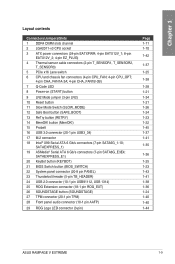
... (SAFE_BOOT) 13 ReTry button (RETRY) 14 MemOK! SATAEXPRESS_E1) 20 KeyBot button (KEYBOT) 21 BIOS Switch button (BIOS_SWITCH) 22 System panel connector (20-8 pin PANEL) 23 Thunderbolt header (5-pin TB_HEADER) 24 USB 2.0 connector (10-1 pin USB91112, USB 1314) 25 ROG Extension connector (18-1 pin ROG_EXT) 26 SOUNDSTAGE button (SOUNDSTAGE) 27 TPM connector... 1-25 1-38 1-28 1-21 1-34 1-21 1-26 1-24 1-23 1-22 1-45 1-37 1-41 1-35 1-36 1-25 1-23 1-43 1-41 1-38 1-36 1-24 1-40 1-40 1-44 ASUS RAMPAGE V EXTREME 1-9
... (SAFE_BOOT) 13 ReTry button (RETRY) 14 MemOK! SATAEXPRESS_E1) 20 KeyBot button (KEYBOT) 21 BIOS Switch button (BIOS_SWITCH) 22 System panel connector (20-8 pin PANEL) 23 Thunderbolt header (5-pin TB_HEADER) 24 USB 2.0 connector (10-1 pin USB91112, USB 1314) 25 ROG Extension connector (18-1 pin ROG_EXT) 26 SOUNDSTAGE button (SOUNDSTAGE) 27 TPM connector... 1-25 1-38 1-28 1-21 1-34 1-21 1-26 1-24 1-23 1-22 1-45 1-37 1-41 1-35 1-36 1-25 1-23 1-43 1-41 1-38 1-36 1-24 1-40 1-40 1-44 ASUS RAMPAGE V EXTREME 1-9
User Guide
Page 59
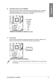
When PCIE_X8_4 is for the add-on Thunderbolt I/O card that supports Intel's Thunderbolt Technology, allowing you to connect up to six Thunderbolt-enabled devices and a DisplayPort-enabled display in a daisy-chain configuration. 11. The PCIE_X8_4 slot shares bandwidth with M Key supports type 2260 (22 mm x 60 mm), 2280 (22 mm x 80 mm), and 22110 (22 mm x 110 mm) PCIe interface storage devices. M.2 connector The M.2 (Socket 3) with M.2 x4. ASUS RAMPAGE V EXTREME 1-41 Thunderbolt header (5-pin TB_HEADER) This connector is occupied, the M.2 will be disabled. Chapter 1 10.
When PCIE_X8_4 is for the add-on Thunderbolt I/O card that supports Intel's Thunderbolt Technology, allowing you to connect up to six Thunderbolt-enabled devices and a DisplayPort-enabled display in a daisy-chain configuration. 11. The PCIE_X8_4 slot shares bandwidth with M Key supports type 2260 (22 mm x 60 mm), 2280 (22 mm x 80 mm), and 22110 (22 mm x 110 mm) PCIe interface storage devices. M.2 connector The M.2 (Socket 3) with M.2 x4. ASUS RAMPAGE V EXTREME 1-41 Thunderbolt header (5-pin TB_HEADER) This connector is occupied, the M.2 will be disabled. Chapter 1 10.
