
User Manual
Page 11
...or removing signal cables from the system, ensure that your area. It could interrupt the grounding circuit. • Ensure that the power cables for the devices are unplugged before the signal cables are connected. RELATED INSTRUCTIONS. Safety information Electrical safety • To prevent electrical... into the environment. • Never dispose of the battery with your local power company. • If the power supply is broken, do not try to fix it to the correct voltage in your power supply is defined as a CLASS 1 LASER PRODUCT. xi Contact a qualified service technician...
...or removing signal cables from the system, ensure that your area. It could interrupt the grounding circuit. • Ensure that the power cables for the devices are unplugged before the signal cables are connected. RELATED INSTRUCTIONS. Safety information Electrical safety • To prevent electrical... into the environment. • Never dispose of the battery with your local power company. • If the power supply is broken, do not try to fix it to the correct voltage in your power supply is defined as a CLASS 1 LASER PRODUCT. xi Contact a qualified service technician...

User Manual
Page 25
...RAMPAGE IV EXTREME 2-1 Failure to do so may cause severe damage to avoid touching the ICs on them. • Whenever you uninstall any component, place it on a grounded antistatic pad or in the bag that came with the component. • Before you install or remove any component, ensure that the ATX power supply... is switched off or the power cord is detached from the power supply. Chapter 2: Chapter 2 Hardware information 2.1 Before you proceed Take note of the following precautions ...
...RAMPAGE IV EXTREME 2-1 Failure to do so may cause severe damage to avoid touching the ICs on them. • Whenever you uninstall any component, place it on a grounded antistatic pad or in the bag that came with the component. • Before you install or remove any component, ensure that the ATX power supply... is switched off or the power cord is detached from the power supply. Chapter 2: Chapter 2 Hardware information 2.1 Before you proceed Take note of the following precautions ...

User Manual
Page 40
... and damage motherboard components. Failure to do so may cause you provide sufficient power when running at heavy loaded four VGA cards, ensure to plug in the 6-pin extra PCIe power supply for stability. • Connect a chassis fan to the motherboard connector labeled CHA_FAN1... slot 3 PCIe 3.0 x8_2B slot 4 PCIe 3.0 x16/8_3 slot 5 PCIe 2.0 x1_1 slot 6 PCIe 3.0 x8_4 slot • Refer to unplug the power cord before adding or removing expansion cards. SLI/CF x16 - See page 2-32 for installation. 2.2.4 Expansion slots Ensure to the following configuration table for details...
... and damage motherboard components. Failure to do so may cause you provide sufficient power when running at heavy loaded four VGA cards, ensure to plug in the 6-pin extra PCIe power supply for stability. • Connect a chassis fan to the motherboard connector labeled CHA_FAN1... slot 3 PCIe 3.0 x8_2B slot 4 PCIe 3.0 x16/8_3 slot 5 PCIe 2.0 x1_1 slot 6 PCIe 3.0 x8_4 slot • Refer to unplug the power cord before adding or removing expansion cards. SLI/CF x16 - See page 2-32 for installation. 2.2.4 Expansion slots Ensure to the following configuration table for details...

User Manual
Page 44
5. Q reset button When the LN2_Mode jumper does not work and your CPU cannot resume function, press the Q reset button to temporarily stop the power supply to find out the faulty one without removing the cards. 6. When one of the installed PCIe x16 cards is out of order, you to enable and disable the corresponding PCIe x16 slots. Chapter 2 2-20 Chapter 2: Hardware information PCIe x16 Lane switch These slide switches allows you can use the slide switch to the CPU and help the CPU recover from a frozen condition.
5. Q reset button When the LN2_Mode jumper does not work and your CPU cannot resume function, press the Q reset button to temporarily stop the power supply to find out the faulty one without removing the cards. 6. When one of the installed PCIe x16 cards is out of order, you to enable and disable the corresponding PCIe x16 slots. Chapter 2 2-20 Chapter 2: Hardware information PCIe x16 Lane switch These slide switches allows you can use the slide switch to the CPU and help the CPU recover from a frozen condition.

User Manual
Page 62
if you connect a high-definition front panel audio module to this connector to [HD]. 12. The power supply plugs are for a chassis-mounted front panel audio I /O module cable to this connector. • We... Hardware information Connect one orientation. Front panel audio connector (10-1 pin AAFP) This connector is set the item to [HD]; ATX power connectors (24-pin EATXPWR; 4-pin EATX12V_1; 8-pin EATX12V_2) These connectors are designed to fit these connectors in the BIOS setup to... want to connect an AC'97 front panel audio module to this connector is for ATX power supply plugs.
if you connect a high-definition front panel audio module to this connector to [HD]. 12. The power supply plugs are for a chassis-mounted front panel audio I /O module cable to this connector. • We... Hardware information Connect one orientation. Front panel audio connector (10-1 pin AAFP) This connector is set the item to [HD]; ATX power connectors (24-pin EATXPWR; 4-pin EATX12V_1; 8-pin EATX12V_2) These connectors are designed to fit these connectors in the BIOS setup to... want to connect an AC'97 front panel audio module to this connector is for ATX power supply plugs.

User Manual
Page 63
...TOP-500P5 Zalman ZM600-HP Zippy HP2-6500PE (G1) ROG RAMPAGE IV EXTREME 2-39 The system may become unstable or may not boot up if the power is recommended when configuring a system with more power-consuming devices. Chapter 2 • For a fully configured ...power supply requirement for details. com/PowerSupplyCalculator/PSCalculator.aspx?SLanguage=en-us for your system, refer to connect the 4-pin/8-pin EATX12 V power plug; otherwise, the system will not boot. • Use of 450 W. • Do not forget to the Recommended Power Supply Wattage Calculator at http://support.asus...
...TOP-500P5 Zalman ZM600-HP Zippy HP2-6500PE (G1) ROG RAMPAGE IV EXTREME 2-39 The system may become unstable or may not boot up if the power is recommended when configuring a system with more power-consuming devices. Chapter 2 • For a fully configured ...power supply requirement for details. com/PowerSupplyCalculator/PSCalculator.aspx?SLanguage=en-us for your system, refer to connect the 4-pin/8-pin EATX12 V power plug; otherwise, the system will not boot. • Use of 450 W. • Do not forget to the Recommended Power Supply Wattage Calculator at http://support.asus...

User Manual
Page 64
... when installing four PCIe3.0 x16 display cards to the DIMMs. 14. Connect a 4-pin power cable to EZ_PLUG_2 to provide stable power supply to provide sufficient power supply. 13. EZ Plug connectors (6-pin EZ_PLUG_1; 4-pin EZ_PLUG_2) The EZ Plug connectors provide additional power to the OC Key device that allows quick on-screen overclocking adjustments. OC Key...
... when installing four PCIe3.0 x16 display cards to the DIMMs. 14. Connect a 4-pin power cable to EZ_PLUG_2 to provide stable power supply to provide sufficient power supply. 13. EZ Plug connectors (6-pin EZ_PLUG_1; 4-pin EZ_PLUG_2) The EZ Plug connectors provide additional power to the OC Key device that allows quick on-screen overclocking adjustments. OC Key...
User Manual
Page 66
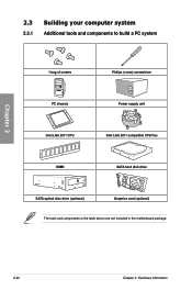
Chapter 2 2.3 Building your computer system 2.3.1 Additional tools and components to build a PC system 1 bag of screws Philips (cross) screwdriver PC chassis Power supply unit Intel LGA 2011 CPU Intel LGA 2011 compatible CPU Fan DIMM SATA hard disk drive SATA optical disc drive (optional) Graphics card (optional) The tools and components in the table above are not included in the motherboard package. 2-42 Chapter 2: Hardware information
Chapter 2 2.3 Building your computer system 2.3.1 Additional tools and components to build a PC system 1 bag of screws Philips (cross) screwdriver PC chassis Power supply unit Intel LGA 2011 CPU Intel LGA 2011 compatible CPU Fan DIMM SATA hard disk drive SATA optical disc drive (optional) Graphics card (optional) The tools and components in the table above are not included in the motherboard package. 2-42 Chapter 2: Hardware information
User Manual
Page 85
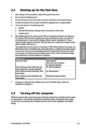
... mode, depending on sleep mode or soft-off the computer While the system is equipped with ATX power supplies, the system LED lights up or change from the time you press the ATX power button. ROG RAMPAGE IV EXTREME 2-61 Connect the power cord to a power outlet that all the connections, replace the system case cover. 2. Connect the...
... mode, depending on sleep mode or soft-off the computer While the system is equipped with ATX power supplies, the system LED lights up or change from the time you press the ATX power button. ROG RAMPAGE IV EXTREME 2-61 Connect the power cord to a power outlet that all the connections, replace the system case cover. 2. Connect the...
User Manual
Page 170
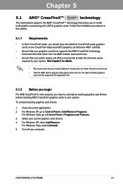
...Uninstall. 5. ROG RAMPAGE IV EXTREME 5-1 Close all existing graphics card drivers before installing AMD CrossFireX graphics cards to your system. Turn off your current graphics card driver/s. 4. Download the latest driver from the AMD website (www.amd.com). • Ensure that your power supply unit (PSU) can... provide at least the minimum power required by your system. �S�e�e��C��h�a�p��te�&#...
...Uninstall. 5. ROG RAMPAGE IV EXTREME 5-1 Close all existing graphics card drivers before installing AMD CrossFireX graphics cards to your system. Turn off your current graphics card driver/s. 4. Download the latest driver from the AMD website (www.amd.com). • Ensure that your power supply unit (PSU) can... provide at least the minimum power required by your system. �S�e�e��C��h�a�p��te�&#...

User Manual
Page 171
... that the connector is firmly in this user manual for the locations of the PCIEX16 slots recommended for reference only. Connect two independent auxiliary power sources from the power supply to the goldfingers on each graphics card. goldfingers 5-2 Chapter 5: Multiple GPU technology support If your motherboard has more than two PCIEX16 slots, refer...
... that the connector is firmly in this user manual for the locations of the PCIEX16 slots recommended for reference only. Connect two independent auxiliary power sources from the power supply to the goldfingers on each graphics card. goldfingers 5-2 Chapter 5: Multiple GPU technology support If your motherboard has more than two PCIEX16 slots, refer...

User Manual
Page 173
...; SLI™ (Scalable Link Interface) technology that allows you should have two identical SLI-ready graphics cards that are for reference only. Ensure that your power supply unit (PSU) can provide at least the minimum power required by your graphics card driver supports the NVIDIA SLI technology.
...; SLI™ (Scalable Link Interface) technology that allows you should have two identical SLI-ready graphics cards that are for reference only. Ensure that your power supply unit (PSU) can provide at least the minimum power required by your graphics card driver supports the NVIDIA SLI technology.
User Manual
Page 174
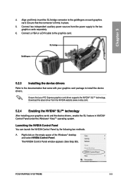
Right click on each graphics card. Chapter 5 4. A. Connect two independent auxiliary power sources from the NVIDIA website (www.nvidia.com). 5.2.4 Enabling the NVIDIA® SLI™ technology After installing your graphics cards and the device...the power supply to install the device drivers. Ensure that the connector is firmly in NVIDIA® Control Panel under the Windows® Vista™ operating system. Connect a VGA or a DVI cable to the goldfingers on the empty space of the Windows® desktop and select NVIDIA Control Panel. ROG RAMPAGE IV EXTREME 5-5...
Right click on each graphics card. Chapter 5 4. A. Connect two independent auxiliary power sources from the NVIDIA website (www.nvidia.com). 5.2.4 Enabling the NVIDIA® SLI™ technology After installing your graphics cards and the device...the power supply to install the device drivers. Ensure that the connector is firmly in NVIDIA® Control Panel under the Windows® Vista™ operating system. Connect a VGA or a DVI cable to the goldfingers on the empty space of the Windows® desktop and select NVIDIA Control Panel. ROG RAMPAGE IV EXTREME 5-5...


