User Guide
Page 13
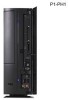
... In port . USB 2.0 ports . ASUS Pundit P1-PH1 system 1-3 Reset button . Headphone port . These Universal Serial Bus 2.0 (USB 2.0) ports are 8 located inside the front panel door. Open the front panel door by 9 pressing the mark. 8. Press this 10 button to reset the system. 9. This Mic (pink) port connects a microphone. 15. This port provides high-speed connectivity for connecting USB 2.0 devices such as a mouse, printer, scanner, camera, PDA, and others. 17. CF card slot . Microphone port . This port connects a headphone with a stereo mini-plug. 16. This port...
... In port . USB 2.0 ports . ASUS Pundit P1-PH1 system 1-3 Reset button . Headphone port . These Universal Serial Bus 2.0 (USB 2.0) ports are 8 located inside the front panel door. Open the front panel door by 9 pressing the mark. 8. Press this 10 button to reset the system. 9. This Mic (pink) port connects a microphone. 15. This port provides high-speed connectivity for connecting USB 2.0 devices such as a mouse, printer, scanner, camera, PDA, and others. 17. CF card slot . Microphone port . This port connects a headphone with a stereo mini-plug. 16. This port...
User Guide
Page 15
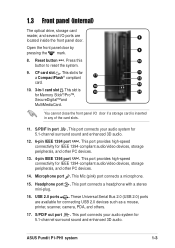
... LFE Output*/Center Front Speaker Out Surround 17. PS/2 keyboard port . This Microphone (pink) port connects a microphone. This Line Out (lime) port connects a headphone or a speaker. In 4/6-channel mode, the function of this port becomes 14 Surround Speaker. 13 15. Power socket. This socket connects the power cable and plug. Line Out port . Microphone port . This Line In (light blue) port connects a tape player or other audio sources. In 4/ 16 6-channel mode, the function...
... LFE Output*/Center Front Speaker Out Surround 17. PS/2 keyboard port . This Microphone (pink) port connects a microphone. This Line Out (lime) port connects a headphone or a speaker. In 4/6-channel mode, the function of this port becomes 14 Surround Speaker. 13 15. Power socket. This socket connects the power cable and plug. Line Out port . Microphone port . This Line In (light blue) port connects a tape player or other audio sources. In 4/ 16 6-channel mode, the function...
User Guide
Page 19
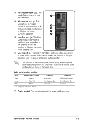
Keep the screws for later use. 4 3 3. Lift the cover, then set aside. Use a Phillips (cross) screw driver to the chassis. 2. Pull the cover slightly toward the rear panel until the cover tabs disengage from the chassis. 4. ASUS Pundit P1-PH1 system 2-3 2.3 Removing the cover To remove the cover: 2 1 1 1. On the rear panel, locate the two screws that secure the cover to remove the cover screws.
Keep the screws for later use. 4 3 3. Lift the cover, then set aside. Use a Phillips (cross) screw driver to the chassis. 2. Pull the cover slightly toward the rear panel until the cover tabs disengage from the chassis. 4. ASUS Pundit P1-PH1 system 2-3 2.3 Removing the cover To remove the cover: 2 1 1 1. On the rear panel, locate the two screws that secure the cover to remove the cover screws.
User Guide
Page 21
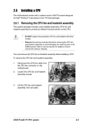
... includes a pre-installed proprietary CPU fan and heatsink assembly to provide an efficient thermal solution to remove the memory modules. 2.6 Installing a CPU The motherboard comes with a surface mount LGA775 socket designed for details on the motherboard. 2. Disconnect the CPU fan cable from the CPU fan connector on how to the CPU. • DO NOT replace the proprietary CPU fan and heatsink with other models. • Remove the memory modules first before installing a CPU. ASUS Pundit P1-PH1 system 2-5
... includes a pre-installed proprietary CPU fan and heatsink assembly to provide an efficient thermal solution to remove the memory modules. 2.6 Installing a CPU The motherboard comes with a surface mount LGA775 socket designed for details on the motherboard. 2. Disconnect the CPU fan cable from the CPU fan connector on how to the CPU. • DO NOT replace the proprietary CPU fan and heatsink with other models. • Remove the memory modules first before installing a CPU. ASUS Pundit P1-PH1 system 2-5
User Guide
Page 23
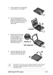
...CPU over the socket, making sure that the gold triangle is on the socket and damaging the CPU! Close the load plate (A), then A push the load lever (B) until it snaps into the socket to prevent bending the connectors on the bottom-left corner of the arrow to remove... to a 100º angle (A), then push the PnP cap from the load plate window to a 135º angle. 4. B A Load plate 5. B The CPU fits in the direction of the socket. The socket alignment key should fit A l i g n m e n t k e y into the CPU notch. 3. Gold triangle mark 6. ASUS Pundit P1-PH1 system 2-7
...CPU over the socket, making sure that the gold triangle is on the socket and damaging the CPU! Close the load plate (A), then A push the load lever (B) until it snaps into the socket to prevent bending the connectors on the bottom-left corner of the arrow to remove... to a 100º angle (A), then push the PnP cap from the load plate window to a 135º angle. 4. B A Load plate 5. B The CPU fits in the direction of the socket. The socket alignment key should fit A l i g n m e n t k e y into the CPU notch. 3. Gold triangle mark 6. ASUS Pundit P1-PH1 system 2-7
User Guide
Page 25
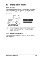
2.7 Installing memory modules 2.7.1 Overview The system motherboard has two DDR II DIMM sockets that support up to section 2.7.3 for the location of qualified DDR vendors. 2.7.2 Memory configurations You may install 64MB, 128MB, 256MB, 512MB, and 1GB DDR II DIMMs to the DIMM sockets. ASUS Pundit P1-PH1 system 2-9 Refer to the illustration below for a list of the DIMM sockets. ® DIMMA1 DIMMB1 240-pin DDR2...
2.7 Installing memory modules 2.7.1 Overview The system motherboard has two DDR II DIMM sockets that support up to section 2.7.3 for the location of qualified DDR vendors. 2.7.2 Memory configurations You may install 64MB, 128MB, 256MB, 512MB, and 1GB DDR II DIMMs to the DIMM sockets. ASUS Pundit P1-PH1 system 2-9 Refer to the illustration below for a list of the DIMM sockets. ® DIMMA1 DIMMB1 240-pin DDR2...
User Guide
Page 27
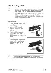
... power supply before installing the DIMM(s) to avoid damaging the retaining clips of the DIMM sockets. Unlock a DIMM socket by pressing the retaining clips outward. 3. ASUS Pundit P1-PH1 system 2-11 Refer to reinstall the CPU fan and heatsink assembly. Firmly insert the DIMM into a socket to both the motherboard and the components. • Reinstall the CPU fan and heatsink assembly before adding...
... power supply before installing the DIMM(s) to avoid damaging the retaining clips of the DIMM sockets. Unlock a DIMM socket by pressing the retaining clips outward. 3. ASUS Pundit P1-PH1 system 2-11 Refer to reinstall the CPU fan and heatsink assembly. Firmly insert the DIMM into a socket to both the motherboard and the components. • Reinstall the CPU fan and heatsink assembly before adding...
User Guide
Page 29
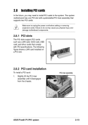
... may cause you may need to install PCI cards to unplug the power cord before adding or removing expansion cards. The following figure shows a LAN card installed on a PCI slot. 2.8.2 PCI card installation To install a PCI card: 1. 2.8 Installing PCI cards In the future, you physical injury and damage motherboard components. 2.8.1 PCI slots The PCI slots support PCI cards such as a LAN card, SCSI card, USB card, and other cards that supports two PCI cards. PCI riser assembly ASUS Pundit P1-PH1 system 2-13 Make sure to the system. Slightly lift the PCI riser assembly until it...
... may cause you may need to install PCI cards to unplug the power cord before adding or removing expansion cards. The following figure shows a LAN card installed on a PCI slot. 2.8.2 PCI card installation To install a PCI card: 1. 2.8 Installing PCI cards In the future, you physical injury and damage motherboard components. 2.8.1 PCI slots The PCI slots support PCI cards such as a LAN card, SCSI card, USB card, and other cards that supports two PCI cards. PCI riser assembly ASUS Pundit P1-PH1 system 2-13 Make sure to the system. Slightly lift the PCI riser assembly until it...
User Guide
Page 31
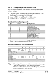
... change the necessary BIOS settings, if any. Turn on shared slots, ensure that the drivers support "Share IRQ" or that the cards do not need IRQ assignments. IRQ assignments for ISA or PCI devices. Onboard USB controller HC0 -- -- -- ASUS Pundit P1-PH1 system 2-15 shared -- Onboard USB 2.0 controller -- -- -- shared -- -- -- Install the software drivers for information on BIOS setup. 2. used 10* 5 IRQ Holder for PCI Steering 11* 6 IRQ Holder for PCI Steering 12* 7 PS/2 Compatible Mouse Port 13 8 Numeric Data Processor...
... change the necessary BIOS settings, if any. Turn on shared slots, ensure that the drivers support "Share IRQ" or that the cards do not need IRQ assignments. IRQ assignments for ISA or PCI devices. Onboard USB controller HC0 -- -- -- ASUS Pundit P1-PH1 system 2-15 shared -- Onboard USB 2.0 controller -- -- -- shared -- -- -- Install the software drivers for information on BIOS setup. 2. used 10* 5 IRQ Holder for PCI Steering 11* 6 IRQ Holder for PCI Steering 12* 7 PS/2 Compatible Mouse Port 13 8 Numeric Data Processor...
User Guide
Page 33
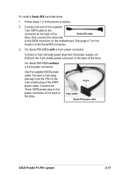
... SATA power cable. To install a Serial ATA hard disk drive: 1. Connect a 4-pin plug (female) from the power supply unit (PSU) to the power connector at the back of the drive. 15-pin 4-pin (male) Serial ATA power cable ASUS Pundit P1-PH1 system 2-17 Connect the 15-pin SATA power plug to the 4-pin (male) power connector at the back of the drive. For Serial ATA HDDs without a 4-pin power connector: Use the supplied SATA power cable. See page 4-7 for the location of the previous section. 2. For Serial ATA HDDs with a 4-pin power connector: Connect a 4-pin (female) power plug...
... SATA power cable. To install a Serial ATA hard disk drive: 1. Connect a 4-pin plug (female) from the power supply unit (PSU) to the power connector at the back of the drive. 15-pin 4-pin (male) Serial ATA power cable ASUS Pundit P1-PH1 system 2-17 Connect the 15-pin SATA power plug to the 4-pin (male) power connector at the back of the drive. For Serial ATA HDDs without a 4-pin power connector: Use the supplied SATA power cable. See page 4-7 for the location of the previous section. 2. For Serial ATA HDDs with a 4-pin power connector: Connect a 4-pin (female) power plug...
User Guide
Page 41
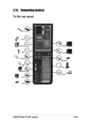
2.13 Connecting devices To the rear panel AC Line In Line Out Mic PS/2 KB USB DVI-D VGA Serial S-Video TV-out PS/2 Mouse RJ-45 Parallel ASUS Pundit P1-PH1 system 2-25
2.13 Connecting devices To the rear panel AC Line In Line Out Mic PS/2 KB USB DVI-D VGA Serial S-Video TV-out PS/2 Mouse RJ-45 Parallel ASUS Pundit P1-PH1 system 2-25
User Guide
Page 45
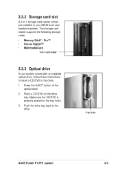
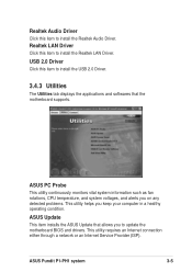
... button of the optical drive. 2. Make sure the CD/DVD is properly seated on the drive tray. 3.3.2 Storage card slot A 3-in-1 storage card reader comes pre-installed in -1 card reader 3.3.3 Optical drive If your ASUS book size barebone system. Tray locks ASUS Pundit P1-PH1 system 3-3 The storage card reader supports the following storage cards: • Memory Stick® / Pro™ • Secure Digital™ • MultimediaCard 3-in your system comes with an installed optical drive, follow these instructions to insert a CD/DVD...
... button of the optical drive. 2. Make sure the CD/DVD is properly seated on the drive tray. 3.3.2 Storage card slot A 3-in-1 storage card reader comes pre-installed in -1 card reader 3.3.3 Optical drive If your ASUS book size barebone system. Tray locks ASUS Pundit P1-PH1 system 3-3 The storage card reader supports the following storage cards: • Memory Stick® / Pro™ • Secure Digital™ • MultimediaCard 3-in your system comes with an installed optical drive, follow these instructions to insert a CD/DVD...

User Guide
Page 46
... came with the system contains useful software and several utility drivers that enhance the system features. • Screen display and driver options may not be the same for updates. 3.4.1 Running the support CD To begin using the support CD, place the CD in your computer. Visit the ASUS website for other information If Autorun is enabled in your optical drive. Install the necessary drivers to locate the file ASSETUP.EXE...
... came with the system contains useful software and several utility drivers that enhance the system features. • Screen display and driver options may not be the same for updates. 3.4.1 Running the support CD To begin using the support CD, place the CD in your computer. Visit the ASUS website for other information If Autorun is enabled in your optical drive. Install the necessary drivers to locate the file ASSETUP.EXE...
User Guide
Page 47
... Internet connection either through a network or an Internet Service Provider (ISP). ASUS Update This item installs the ASUS Update that the motherboard supports. USB 2.0 Driver Click this item to update the motherboard BIOS and drivers. Realtek Audio Driver Click this item to install the Realtek LAN Driver. ASUS Pundit P1-PH1 system 3-5 ASUS PC Probe This utility continuously monitors vital system information such as fan rotations, CPU temperature, and system voltages, and alerts you on any detected problems. This utility helps you to install the USB 2.0 Driver. 3.4.3 Utilities...
... Internet connection either through a network or an Internet Service Provider (ISP). ASUS Update This item installs the ASUS Update that the motherboard supports. USB 2.0 Driver Click this item to update the motherboard BIOS and drivers. Realtek Audio Driver Click this item to install the Realtek LAN Driver. ASUS Pundit P1-PH1 system 3-5 ASUS PC Probe This utility continuously monitors vital system information such as fan rotations, CPU temperature, and system voltages, and alerts you on any detected problems. This utility helps you to install the USB 2.0 Driver. 3.4.3 Utilities...
User Guide
Page 53
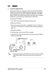
... CMOS. Remove the battery. 3. ASUS Pundit P1-PH1 system 4-3 4.3 Jumper 1. Clear RTC RAM (CLRTC) This jumper allows you to pins 1-2. 4. Plug the power cord and turn ON the computer. 6. Removing the cap will cause system boot failure. Hold down the key during the boot process and enter BIOS setup to pins 2-3. To erase the RTC RAM: 1. Turn OFF the computer and unplug the power cord. 2. CLRTC 12 23 NORMAL CLEAR RTC (Default) ® Clear RTC RAM Except when clearing the RTC RAM, never remove...
... CMOS. Remove the battery. 3. ASUS Pundit P1-PH1 system 4-3 4.3 Jumper 1. Clear RTC RAM (CLRTC) This jumper allows you to pins 1-2. 4. Plug the power cord and turn ON the computer. 6. Removing the cap will cause system boot failure. Hold down the key during the boot process and enter BIOS setup to pins 2-3. To erase the RTC RAM: 1. Turn OFF the computer and unplug the power cord. 2. CLRTC 12 23 NORMAL CLEAR RTC (Default) ® Clear RTC RAM Except when clearing the RTC RAM, never remove...
User Guide
Page 55
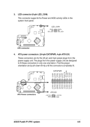
... plugs from the power supply unit. ATX power connectors (24-pin EATXPWR, 4-pin ATX12V) These connectors are for the 24-pin and 4-pin power plugs from the power supply unit are designed to fit these connectors in the system front panel. Find the proper orientation and push down firmly until the connectors completely fit. LED connector (6-pin LED_CON) This connector supports the Power and HDD activity LEDs in only one orientation. PLED+ NC IDE_LED+ ® LED connector...
... plugs from the power supply unit. ATX power connectors (24-pin EATXPWR, 4-pin ATX12V) These connectors are for the 24-pin and 4-pin power plugs from the power supply unit are designed to fit these connectors in the system front panel. Find the proper orientation and push down firmly until the connectors completely fit. LED connector (6-pin LED_CON) This connector supports the Power and HDD activity LEDs in only one orientation. PLED+ NC IDE_LED+ ® LED connector...

User Guide
Page 57
... connector supports the rear panel serial port. ® Serial COM1 connector COM1 ASUS Pundit P1-PH1 system 4-7 Serial ATA connector (7-pin SATA1) This next generation connector supports the thin Serial ATA cable for Serial ATA drive and connections. • Install Windows® XP™ Service Pack 1 when using Serial ATA. 7. The lower pin count of the Serial ATA cable eliminates the problem caused by the wide, flat ribbon cables of the Parallel ATA interface. • This motherboard does not support hot plug function for a Serial ATA hard disk drive...
... connector supports the rear panel serial port. ® Serial COM1 connector COM1 ASUS Pundit P1-PH1 system 4-7 Serial ATA connector (7-pin SATA1) This next generation connector supports the thin Serial ATA cable for Serial ATA drive and connections. • Install Windows® XP™ Service Pack 1 when using Serial ATA. 7. The lower pin count of the Serial ATA cable eliminates the problem caused by the wide, flat ribbon cables of the Parallel ATA interface. • This motherboard does not support hot plug function for a Serial ATA hard disk drive...
User Guide
Page 63
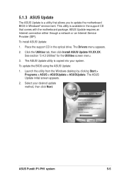
... Internet connection either through a network or an Internet Service Provider (ISP). Place the support CD in the support CD that allows you to update the motherboard BIOS in Windows® environment. The ASUS Update utility is a utility that comes with the motherboard package. The ASUS Update initial screen appears. 2. To update the BIOS using the ASUS Update: 1. Launch the utility from the Windows desktop by clicking Start > Programs > ASUS > ASUSUpdate > ASUSUpdate. Select your system. This utility is available in the optical drive. ASUS Pundit P1-PH1...
... Internet connection either through a network or an Internet Service Provider (ISP). Place the support CD in the support CD that allows you to update the motherboard BIOS in Windows® environment. The ASUS Update utility is a utility that comes with the motherboard package. The ASUS Update initial screen appears. 2. To update the BIOS using the ASUS Update: 1. Launch the utility from the Windows desktop by clicking Start > Programs > ASUS > ASUSUpdate > ASUSUpdate. Select your system. This utility is available in the optical drive. ASUS Pundit P1-PH1...

User Guide
Page 75
.../IRQ7] Parallel Port Mode [ECP+EPP] Allows you to enable or disable the option ROM on the onboard LAN chipset. If there are not user-configurable. Configuration options: [Auto] [Disabled] Onboard Chip SATA [IDE Controller] Allows you to set the graphics controller to set the operation mode of the onboard parallel port connector. Configuration options: [SATA Disabled] [IDE Controller] Primary Display Adapter [PCI] Allows you to set the base address of the parallel port. If you to use as the primary boot device. Configuration options: [1] [3] ASUS Pundit P1-PH1 system 5-17...
.../IRQ7] Parallel Port Mode [ECP+EPP] Allows you to enable or disable the option ROM on the onboard LAN chipset. If there are not user-configurable. Configuration options: [Auto] [Disabled] Onboard Chip SATA [IDE Controller] Allows you to set the graphics controller to set the operation mode of the onboard parallel port connector. Configuration options: [SATA Disabled] [IDE Controller] Primary Display Adapter [PCI] Allows you to set the base address of the parallel port. If you to use as the primary boot device. Configuration options: [1] [3] ASUS Pundit P1-PH1 system 5-17...
User Guide
Page 76
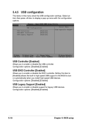
... USB configuration settings. Select an item then press to turn on automatically when you to enable or disable the USB controller. Configuration options: [Disabled] [Enabled] USB Legacy Support [Enabled] Allows you install high speed USB devices. USB Configuration USB Controller USB EHCI Controller USB Legacy Support [Enabled] [Enabled] [Enabled] Select Menu Item Specific Help USB Controller [Enabled] Allows you to enable or disable the EHCI controller. Configuration options: [Disabled] [Enabled] 5-18 Chapter 5: BIOS setup Configuration options: [Disabled] [Enabled] USB...
... USB configuration settings. Select an item then press to turn on automatically when you to enable or disable the USB controller. Configuration options: [Disabled] [Enabled] USB Legacy Support [Enabled] Allows you install high speed USB devices. USB Configuration USB Controller USB EHCI Controller USB Legacy Support [Enabled] [Enabled] [Enabled] Select Menu Item Specific Help USB Controller [Enabled] Allows you to enable or disable the EHCI controller. Configuration options: [Disabled] [Enabled] 5-18 Chapter 5: BIOS setup Configuration options: [Disabled] [Enabled] USB...


