
Users Manual English
Page 1
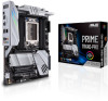
Motherboard PRIME TRX40PRO
Motherboard PRIME TRX40PRO

Users Manual English
Page 3
...information...vi About this guide...vii PRIME TRX40-PRO specifications summary ix Package contents...xiv Installation tools and components xv Chapter 1: Product Introduction 1.1 Before you proceed 1-1 1.2 Motherboard layout 1-2 1.3 Central Processing ... connectors 1-13 Chapter 2: Basic Installation 2.1 Building your PC system 2-1 2.1.1 CPU installation 2-1 2.1.2 Cooling system installation 2-4 2.1.3 Motherboard installation 2-5 2.1.4 DIMM installation 2-6 2.1.5 ATX power connection 2-7 2.1.6 SATA device connection 2-8 2.1.7 Front I/O connector 2-9 2.1.8 Expansion...
...information...vi About this guide...vii PRIME TRX40-PRO specifications summary ix Package contents...xiv Installation tools and components xv Chapter 1: Product Introduction 1.1 Before you proceed 1-1 1.2 Motherboard layout 1-2 1.3 Central Processing ... connectors 1-13 Chapter 2: Basic Installation 2.1 Building your PC system 2-1 2.1.1 CPU installation 2-1 2.1.2 Cooling system installation 2-4 2.1.3 Motherboard installation 2-5 2.1.4 DIMM installation 2-6 2.1.5 ATX power connection 2-7 2.1.6 SATA device connection 2-8 2.1.7 Front I/O connector 2-9 2.1.8 Expansion...

Users Manual English
Page 6
Operation safety • Before installing the motherboard and adding devices on a stable surface. • If you are using, contact your area. If you are not sure about the voltage of the electrical ... all cables are correctly connected and the power cables are not damaged. If you add a device. • Before connecting or removing signal cables from the motherboard, ensure that all power cables from the existing system before you detect any area where it may become wet. • Place the product on it...
Operation safety • Before installing the motherboard and adding devices on a stable surface. • If you are using, contact your area. If you are not sure about the voltage of the electrical ... all cables are correctly connected and the power cables are not damaged. If you add a device. • Before connecting or removing signal cables from the motherboard, ensure that all power cables from the existing system before you detect any area where it may become wet. • Place the product on it...

Users Manual English
Page 7
...that may include optional documentation, such as warranty flyers, that you need when installing and configuring the motherboard. It includes description of the switches, jumpers, and connectors on ASUS hardware and software products. 2. Optional documentation Your product package may have to perform when installing system components... and for product and software updates. 1. Detailed descriptions of the BIOS parameters are not part of the motherboard and the new technology it supports. How this guide This user guide contains the information you have been added by your ...
...that may include optional documentation, such as warranty flyers, that you need when installing and configuring the motherboard. It includes description of the switches, jumpers, and connectors on ASUS hardware and software products. 2. Optional documentation Your product package may have to perform when installing system components... and for product and software updates. 1. Detailed descriptions of the BIOS parameters are not part of the motherboard and the new technology it supports. How this guide This user guide contains the information you have been added by your ...

Users Manual English
Page 14
xiv Package contents Check your motherboard package for the following items. Motherboard Cables Accessories Application DVD Documentation 1 x PRIME TRX40-PRO motherboard 1 x Addressable LED extension cable 1 x RGB LED extension cable 4 x SATA 6.0Gb/s cables 1 x M.2 Screw package 1 x M.2 E-key Screw package 1 x M.2 22110 vertical bracket 1 x FAN holder 1 x Q-connector 1 x Motherboard support DVD 1 x User guide If any of the above items is damaged or missing, contact your retailer.
xiv Package contents Check your motherboard package for the following items. Motherboard Cables Accessories Application DVD Documentation 1 x PRIME TRX40-PRO motherboard 1 x Addressable LED extension cable 1 x RGB LED extension cable 4 x SATA 6.0Gb/s cables 1 x M.2 Screw package 1 x M.2 E-key Screw package 1 x M.2 22110 vertical bracket 1 x FAN holder 1 x Q-connector 1 x Motherboard support DVD 1 x User guide If any of the above items is damaged or missing, contact your retailer.

Users Manual English
Page 15
xv Installation tools and components 1 Bag of screws PC chassis Screwdriver Power supply unit AMD Socket sTRX4 CPU AMD Socket sTRX4 compatible CPU Fan DDR4 DIMM SATA hard disk drive SATA optical disc drive (optional) Graphics card (optional) The tools and components in the table above are not included in the motherboard package.
xv Installation tools and components 1 Bag of screws PC chassis Screwdriver Power supply unit AMD Socket sTRX4 CPU AMD Socket sTRX4 compatible CPU Fan DDR4 DIMM SATA hard disk drive SATA optical disc drive (optional) Graphics card (optional) The tools and components in the table above are not included in the motherboard package.

Users Manual English
Page 17
...that the ATX power supply is switched off or the power cord is detached from the wall socket before you install motherboard components or change any component, place it on a grounded antistatic pad or in this section may cause severe damage to the... to static electricity. • Hold components by the edges to do so may require additional purchase. PRIME TRX40-PRO 1-1 Chapter 1 Chapter 1: Product Introduction Product Introduction 1 1.1 Before you proceed Take note of your motherboard package. • Unplug the power cord from the power supply. Failure to avoid touching the ICs...
...that the ATX power supply is switched off or the power cord is detached from the wall socket before you install motherboard components or change any component, place it on a grounded antistatic pad or in this section may cause severe damage to the... to static electricity. • Hold components by the edges to do so may require additional purchase. PRIME TRX40-PRO 1-1 Chapter 1 Chapter 1: Product Introduction Product Introduction 1 1.1 Before you proceed Take note of your motherboard package. • Unplug the power cord from the power supply. Failure to avoid touching the ICs...

Users Manual English
Page 18
1.2 Motherboard layout Chapter 1 Refer to Internal connectors and Rear I/O connection for more information about rear panel connectors and internal connectors. 1-2 Chapter 1: Product Introduction
1.2 Motherboard layout Chapter 1 Refer to Internal connectors and Rear I/O connection for more information about rear panel connectors and internal connectors. 1-2 Chapter 1: Product Introduction

Users Manual English
Page 20
... will void any applicable AMD product warranty, even when such overclocking is enabled via AMD hardware and/or software. Chapter 1 1.3 Central Processing Unit (CPU) The motherboard comes with an AMD Socket sTRX4 for the Socket sTRX4. • The CPU fits in only one correct orientation. Ensure that may also void warranties...
... will void any applicable AMD product warranty, even when such overclocking is enabled via AMD hardware and/or software. Chapter 1 1.3 Central Processing Unit (CPU) The motherboard comes with an AMD Socket sTRX4 for the Socket sTRX4. • The CPU fits in only one correct orientation. Ensure that may also void warranties...
Users Manual English
Page 21
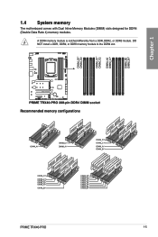
Recommended memory configurations PRIME TRX40-PRO 1-5 DO NOT install a DDR, DDR2, or DDR3 memory module to the DDR4 slot. A DDR4 memory module is notched differently from a DDR, DDR2, or DDR3 module. Chapter 1 1.4 System memory The motherboard comes with Dual Inline Memory Modules (DIMM) slots designed for DDR4 (Double Data Rate 4) memory modules.
Recommended memory configurations PRIME TRX40-PRO 1-5 DO NOT install a DDR, DDR2, or DDR3 memory module to the DDR4 slot. A DDR4 memory module is notched differently from a DDR, DDR2, or DDR3 module. Chapter 1 1.4 System memory The motherboard comes with Dual Inline Memory Modules (DIMM) slots designed for DDR4 (Double Data Rate 4) memory modules.
Users Manual English
Page 23
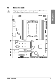
Failure to do so may cause you physical injury and damage motherboard components. Chapter 1 PRIME TRX40-PRO 1-7 1.5 Expansion slots Unplug the power cord before adding or removing expansion cards.
Failure to do so may cause you physical injury and damage motherboard components. Chapter 1 PRIME TRX40-PRO 1-7 1.5 Expansion slots Unplug the power cord before adding or removing expansion cards.
Users Manual English
Page 25
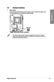
Chapter 1 1.6 Onboard buttons 1. PRIME TRX40-PRO 1-9 Power button Press the Power button to a power source, indicating that you should shut down the system and unplug the power cable before removing or installing any motherboard component. The button also lights up when the system is plugged to power up the system, or put the system into sleep or softoff mode (depending on the operating system settings).
Chapter 1 1.6 Onboard buttons 1. PRIME TRX40-PRO 1-9 Power button Press the Power button to a power source, indicating that you should shut down the system and unplug the power cable before removing or installing any motherboard component. The button also lights up when the system is plugged to power up the system, or put the system into sleep or softoff mode (depending on the operating system settings).
Users Manual English
Page 27
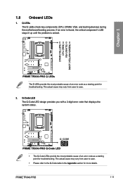
... cause of an error code as a starting point for more details. Q LEDs The Q LEDs check key components (CPU, DRAM, VGA, and booting devices) during the motherboard booting process. If an error is found, the critical component's LED stays lit up until the problem is solved. 1.8 Onboard LEDs 1. PRIME TRX40-PRO 1-11
... cause of an error code as a starting point for more details. Q LEDs The Q LEDs check key components (CPU, DRAM, VGA, and booting devices) during the motherboard booting process. If an error is found, the critical component's LED stays lit up until the problem is solved. 1.8 Onboard LEDs 1. PRIME TRX40-PRO 1-11

Users Manual English
Page 32
Doing so will damage the motherboard! The USB 2.0 module is for additional USB 2.0 ports. Chipset Fan connector The Chipset Fan connector is purchased separately. 7. The USB 2.0 connector provides data transfer speeds of up to the USB connectors. USB 2.0 connector The USB 2.0 connector allows you to connect a USB module for connecting the chipset fan on the integrated heatsink. 1-16 Chapter 1: Product Introduction Chapter 1 6. DO NOT connect a 1394 cable to 480 MB/s connection speed.
Doing so will damage the motherboard! The USB 2.0 module is for additional USB 2.0 ports. Chipset Fan connector The Chipset Fan connector is purchased separately. 7. The USB 2.0 connector provides data transfer speeds of up to the USB connectors. USB 2.0 connector The USB 2.0 connector allows you to connect a USB module for connecting the chipset fan on the integrated heatsink. 1-16 Chapter 1: Product Introduction Chapter 1 6. DO NOT connect a 1394 cable to 480 MB/s connection speed.
Users Manual English
Page 33
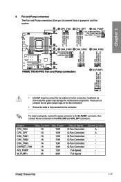
8. Insufficient air flow inside the system may damage the motherboard components. PRIME TRX40-PRO 1-17 Chapter 1 • DO NOT forget to connect the fan cables to the CPU_FAN and CPU_OPT connectors. Do not place jumper caps on the fan ...
8. Insufficient air flow inside the system may damage the motherboard components. PRIME TRX40-PRO 1-17 Chapter 1 • DO NOT forget to connect the fan cables to the CPU_FAN and CPU_OPT connectors. Do not place jumper caps on the fan ...

Users Manual English
Page 34
Chapter 1 Visit www.asus.com for more information about the devices and the latest compatibility list. 10. Connect the thermal sensor and place it on the device or the motherboard's component to connect a compatible PSU or control a compatible fan extension card. 9. Node connector The... connector allows you to connect a sensor to monitor the temperature of the devices and the critical components inside the motherboard. The thermal sensor is purchased separately. 1-18 Chapter 1: Product Introduction Thermal Sensor connector The Thermal Sensor connector allows you to detect...
Chapter 1 Visit www.asus.com for more information about the devices and the latest compatibility list. 10. Connect the thermal sensor and place it on the device or the motherboard's component to connect a compatible PSU or control a compatible fan extension card. 9. Node connector The... connector allows you to connect a sensor to monitor the temperature of the devices and the critical components inside the motherboard. The thermal sensor is purchased separately. 1-18 Chapter 1: Product Introduction Thermal Sensor connector The Thermal Sensor connector allows you to detect...
Users Manual English
Page 35
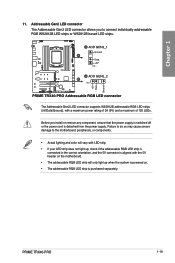
...to connect individually addressable RGB WS2812B LED strips or WS2812B based LED strips. PRIME TRX40-PRO 1-19 The Addressable Gen2 LED connector supports WS2812B addressable RGB LED strips (5V/Data/Ground), with the 5V header on the motherboard. • The addressable RGB LED strip will vary with LED strip. &#...up when the system is powered on. • The addressable RGB LED strip is detached from the power supply. Before you to the motherboard, peripherals, or components. • Actual lighting and color will only light up , check if the addressable RGB LED strip is connected ...
...to connect individually addressable RGB WS2812B LED strips or WS2812B based LED strips. PRIME TRX40-PRO 1-19 The Addressable Gen2 LED connector supports WS2812B addressable RGB LED strips (5V/Data/Ground), with the 5V header on the motherboard. • The addressable RGB LED strip will vary with LED strip. &#...up when the system is powered on. • The addressable RGB LED strip is detached from the power supply. Before you to the motherboard, peripherals, or components. • Actual lighting and color will only light up , check if the addressable RGB LED strip is connected ...

Users Manual English
Page 36
..., or components. • Actual lighting and color will only light up when the system is powered on the motherboard. • The LED strip will vary with LED strip. • If your LED strip does not light up, check if the RGB LED extension cable ...
..., or components. • Actual lighting and color will only light up when the system is powered on the motherboard. • The LED strip will vary with LED strip. • If your LED strip does not light up, check if the RGB LED extension cable ...
Users Manual English
Page 37
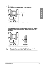
We recommend that supports HD Audio. LED connector The LED connector is for connecting the LED PCB on your I/O cover. Connect one end of the front panel audio I /O module that you connect a high-definition front panel audio module to avail of the motherboard's high-definition audio capability. Chapter 1 14. 13. PRIME TRX40-PRO 1-21 Front Panel Audio connector The front panel audio connector is for a chassis-mounted front panel audio I /O module cable to this connector to this connector.
We recommend that supports HD Audio. LED connector The LED connector is for connecting the LED PCB on your I/O cover. Connect one end of the front panel audio I /O module that you connect a high-definition front panel audio module to avail of the motherboard's high-definition audio capability. Chapter 1 14. 13. PRIME TRX40-PRO 1-21 Front Panel Audio connector The front panel audio connector is for a chassis-mounted front panel audio I /O module cable to this connector to this connector.
Users Manual English
Page 39
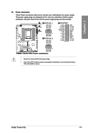
The power supply plugs are designed to fit in only one orientation, find the proper orientation and push down firmly until the power supply plugs are fully inserted. • Ensure to connect both 8-pin power plugs. • Due to a power supply. PRIME TRX40-PRO 1-23 Power connectors These Power connectors allow you to connect your motherboard to the CPU minimum power consumption requirement, we recommend using a PSU with 850W or above. Chapter 1 16.
The power supply plugs are designed to fit in only one orientation, find the proper orientation and push down firmly until the power supply plugs are fully inserted. • Ensure to connect both 8-pin power plugs. • Due to a power supply. PRIME TRX40-PRO 1-23 Power connectors These Power connectors allow you to connect your motherboard to the CPU minimum power consumption requirement, we recommend using a PSU with 850W or above. Chapter 1 16.


