
User Guide
Page 15
... your package with the list below. 1.2 Package contents Check your motherboard package for the following items. Motherboard ASUS PVL-D Series motherboard Cables 2 x Serial ATA signal cables 1 x Serial ATA power cable (dual-plug) 2 x SCSI Ultra320 cables (PVL-D/CSI model only) 80-conductor IDE cable 3-in the long line of the above items is damaged...
... your package with the list below. 1.2 Package contents Check your motherboard package for the following items. Motherboard ASUS PVL-D Series motherboard Cables 2 x Serial ATA signal cables 1 x Serial ATA power cable (dual-plug) 2 x SCSI Ultra320 cables (PVL-D/CSI model only) 80-conductor IDE cable 3-in the long line of the above items is damaged...

User Guide
Page 17
...Mbps bandwidth on USB 1.1 to Gigabit bandwidth. See page 2-20 for details. Zero-Channel RAID (ZCR) solution (PVL-D/SCSI model only) The motherboard comes with dual Gigabit LAN controllers and ports to provide a total solution for your ... Serial ATA interfaces controlled by carrying data in packets. The SATA specification allows for details. Ultra320 SCSI feature (PVL-D/SCSI model only) The Adaptec® AIC-7902W PCI-X SCSI controller is backward compatible with existing PCI or ..., and have network throughput close to a fast 480 Mbps on USB 2.0. ASUS PVL-D Series 1-3
...Mbps bandwidth on USB 1.1 to Gigabit bandwidth. See page 2-20 for details. Zero-Channel RAID (ZCR) solution (PVL-D/SCSI model only) The motherboard comes with dual Gigabit LAN controllers and ports to provide a total solution for your ... Serial ATA interfaces controlled by carrying data in packets. The SATA specification allows for details. Ultra320 SCSI feature (PVL-D/SCSI model only) The Adaptec® AIC-7902W PCI-X SCSI controller is backward compatible with existing PCI or ..., and have network throughput close to a fast 480 Mbps on USB 2.0. ASUS PVL-D Series 1-3

User Guide
Page 20
Chapter summary 2 2.1 Before you proceed 2-1 2.2 Motherboard overview 2-2 2.3 Central Processing Unit (CPU 2-10 2.4 System memory 2-14 2.5 Expansion slots 2-17 2.6 Jumpers 2-21 2.7 Connectors 2-26 ASUS PVL-D Series
Chapter summary 2 2.1 Before you proceed 2-1 2.2 Motherboard overview 2-2 2.3 Central Processing Unit (CPU 2-10 2.4 System memory 2-14 2.5 Expansion slots 2-17 2.6 Jumpers 2-21 2.7 Connectors 2-26 ASUS PVL-D Series
User Guide
Page 21
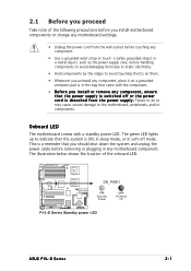
...; SB_PWR1 ON Standby Power OFF Powered Off PVL-D Series Standby power LED ASUS PVL-D Series 2-1 The illustration below shows the location of the following precautions before you install motherboard components or change any motherboard settings. • Unplug the power ...
...; SB_PWR1 ON Standby Power OFF Powered Off PVL-D Series Standby power LED ASUS PVL-D Series 2-1 The illustration below shows the location of the following precautions before you install motherboard components or change any motherboard settings. • Unplug the power ...

User Guide
Page 23
... the CPU heatsinks, your chassis is S S I E E B 3 . 5 c o m p l i a n t, we recommend that you use the CEK springs; Each CEK spring has four hooks to the CPU1 heatsink holes. ASUS PVL-D Series 2-3
... the CPU heatsinks, your chassis is S S I E E B 3 . 5 c o m p l i a n t, we recommend that you use the CEK springs; Each CEK spring has four hooks to the CPU1 heatsink holes. ASUS PVL-D Series 2-3

User Guide
Page 25
6. Refer to section "2.2.2 Screw holes" for CPU2 7. ASUS PVL-D Series 2-5 Before installing the motherboard into the chassis, locate the standoffs that the standoffs perfectly match the CEK spring screw holes; Install the motherboard with ...
6. Refer to section "2.2.2 Screw holes" for CPU2 7. ASUS PVL-D Series 2-5 Before installing the motherboard into the chassis, locate the standoffs that the standoffs perfectly match the CEK spring screw holes; Install the motherboard with ...
User Guide
Page 31
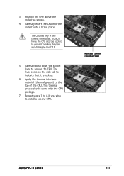
.... 6. This thermal grease should come with the CPU package. 7. Repeat steps 1 to 6 if you wish to the top of the CPU. Marked corner (gold arrow) ASUS PVL-D Series 2-11 Carefully insert the CPU into the socket to prevent bending the pins and damaging the CPU! 5. Carefully push down the socket lever to...
.... 6. This thermal grease should come with the CPU package. 7. Repeat steps 1 to 6 if you wish to the top of the CPU. Marked corner (gold arrow) ASUS PVL-D Series 2-11 Carefully insert the CPU into the socket to prevent bending the pins and damaging the CPU! 5. Carefully push down the socket lever to...
User Guide
Page 33
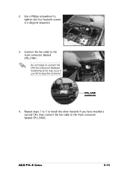
Connect the fan cable to connect the CPU fan connector! Hardware monitoring errors may occur if you have installed a second CPU, then connect the fan cable to the 4-pin connector labeled CPU_FAN2. Repeat steps 1 to 3 to install the other heatsink if you fail to tighten the four heatsink screws in a diagonal sequence. 3. 2. Do not forget to the 4-pin connector labeled CPU_FAN1. Use a Phillips screwdriver to plug this connector. ASUS PVL-D Series 2-13 CPU_FAN1 connector 4.
Connect the fan cable to connect the CPU fan connector! Hardware monitoring errors may occur if you have installed a second CPU, then connect the fan cable to the 4-pin connector labeled CPU_FAN2. Repeat steps 1 to 3 to install the other heatsink if you fail to tighten the four heatsink screws in a diagonal sequence. 3. 2. Do not forget to the 4-pin connector labeled CPU_FAN1. Use a Phillips screwdriver to plug this connector. ASUS PVL-D Series 2-13 CPU_FAN1 connector 4.

User Guide
Page 35
Single rank population MCH Single and dual rank mixing MCH Dual rank population MCH ASUS PVL-D Series Single Rank DIMM B4 Single Rank DIMM A4 Single Rank DIMM B3 Single Rank DIMM A3 Single Rank DIMM B2 Single Rank DIMM A2 Single Rank DIMM B1 Single Rank DIMM A1 Dual Rank DIMM B4 Dual Rank DIMM A4 Single Rank DIMM B3 Single Rank DIMM A3 Single Rank DIMM B2 Single Rank DIMM A2 EMPTY EMPTY Dual Rank DIMM B4 Dual Rank DIMM A4 Dual Rank DIMM B3 Dual Rank DIMM A3 EMPTY B2 EMPTY A2 EMPTY B1 EMPTY A1 2-15
Single rank population MCH Single and dual rank mixing MCH Dual rank population MCH ASUS PVL-D Series Single Rank DIMM B4 Single Rank DIMM A4 Single Rank DIMM B3 Single Rank DIMM A3 Single Rank DIMM B2 Single Rank DIMM A2 Single Rank DIMM B1 Single Rank DIMM A1 Dual Rank DIMM B4 Dual Rank DIMM A4 Single Rank DIMM B3 Single Rank DIMM A3 Single Rank DIMM B2 Single Rank DIMM A2 EMPTY EMPTY Dual Rank DIMM B4 Dual Rank DIMM A4 Dual Rank DIMM B3 Dual Rank DIMM A3 EMPTY B2 EMPTY A2 EMPTY B1 EMPTY A1 2-15

User Guide
Page 37
... the card to use . 4. 2.5 Expansion slots In the future, you physical injury and damage motherboard components. 2.5.1 Installing an expansion card To install an expansion card: 1. ASUS PVL-D Series 2-17 Align the card connector with the slot and press firmly until the card is already installed in a chassis). 3.
... the card to use . 4. 2.5 Expansion slots In the future, you physical injury and damage motherboard components. 2.5.1 Installing an expansion card To install an expansion card: 1. ASUS PVL-D Series 2-17 Align the card connector with the slot and press firmly until the card is already installed in a chassis). 3.
User Guide
Page 39
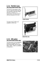
The figure shows a RAID card installed on a PCI-X slot. 32-bit PCI slot 64-bit PCI-X slot 2.5.5 ZCR socket (For PVL-D/SCSI model only) The ZCR socket on a PCI slot. 2.5.4 PCI/PCI-X slots (For PVL-D/SCSI model only) The PCI/PCI-X slots support cards such as a LAN card, SCSI card, USB card, and other cards that allow RAID 0, RAID 1, RAID 10, and RAID 5 configurations. The figure shows a LAN card installed on the motherboard supports the Adaptec AIC-2015 Zero-Channel RAID cards that comply with PCI 2.3 and PCI-X 1.0 specifications. ASUS PVL-D Series 2-19
The figure shows a RAID card installed on a PCI-X slot. 32-bit PCI slot 64-bit PCI-X slot 2.5.5 ZCR socket (For PVL-D/SCSI model only) The ZCR socket on a PCI slot. 2.5.4 PCI/PCI-X slots (For PVL-D/SCSI model only) The PCI/PCI-X slots support cards such as a LAN card, SCSI card, USB card, and other cards that allow RAID 0, RAID 1, RAID 10, and RAID 5 configurations. The figure shows a LAN card installed on the motherboard supports the Adaptec AIC-2015 Zero-Channel RAID cards that comply with PCI 2.3 and PCI-X 1.0 specifications. ASUS PVL-D Series 2-19
User Guide
Page 41
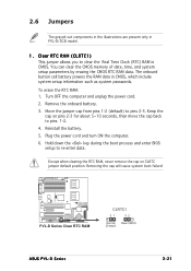
... RTC RAM (CLRTC1) This jumper allows you to pins 1-2. 4. Turn OFF the computer and unplug the power cord. 2. PVL-D Series ® PVL-D Series Clear RTC RAM CLRTC1 21 32 Normal Clear CMOS (Default) ASUS PVL-D Series 2-21 Plug the power cord and turn ON the computer. 6. Remove the onboard battery. 3. The onboard button cell...
... RTC RAM (CLRTC1) This jumper allows you to pins 1-2. 4. Turn OFF the computer and unplug the power cord. 2. PVL-D Series ® PVL-D Series Clear RTC RAM CLRTC1 21 32 Normal Clear CMOS (Default) ASUS PVL-D Series 2-21 Plug the power cord and turn ON the computer. 6. Remove the onboard battery. 3. The onboard button cell...

User Guide
Page 43
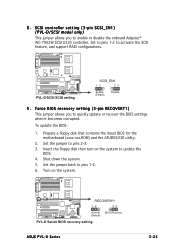
... (3-pin VGA_EN1) These jumpers allow you to enable or disable the onboard ATI® RAGE-XL PCI VGA controller. PVL-D Series ® KBPWR1 21 32 +5V (Default) +5VSB PVL-D Series Keyboard power setting 5 . Set to pins 1-2 to wake up feature. This feature requires an ATX power ...supply that can supply at least 1A on the keyboard (the default is the Space Bar). PVL-D Series ® PVL-D Series VGA setting VGA_EN1 1 2 Enable (Default) 2 3 Disable ASUS PVL-D Series 2-23 Set this jumper to pins 2-3 (+5VSB) to activate the VGA feature. 4.
... (3-pin VGA_EN1) These jumpers allow you to enable or disable the onboard ATI® RAGE-XL PCI VGA controller. PVL-D Series ® KBPWR1 21 32 +5V (Default) +5VSB PVL-D Series Keyboard power setting 5 . Set to pins 1-2 to wake up feature. This feature requires an ATX power ...supply that can supply at least 1A on the keyboard (the default is the Space Bar). PVL-D Series ® PVL-D Series VGA setting VGA_EN1 1 2 Enable (Default) 2 3 Disable ASUS PVL-D Series 2-23 Set this jumper to pins 2-3 (+5VSB) to activate the VGA feature. 4.
User Guide
Page 45
... jumper allows you to pins 1-2. 6. To update the BIOS: 1. Insert the floppy disk then turn on the system. PVL-D Series ® RECOVERY1 12 23 Normal BIOS Recovery (Default) PVL-D Series BIOS recovery setting ASUS PVL-D Series 2-25 Prepare a floppy disk that contains the latest BIOS for the motherboard (xxxx-xxx.ROM) and the AFUDOS...
... jumper allows you to pins 1-2. 6. To update the BIOS: 1. Insert the floppy disk then turn on the system. PVL-D Series ® RECOVERY1 12 23 Normal BIOS Recovery (Default) PVL-D Series BIOS recovery setting ASUS PVL-D Series 2-25 Prepare a floppy disk that contains the latest BIOS for the motherboard (xxxx-xxx.ROM) and the AFUDOS...
User Guide
Page 47
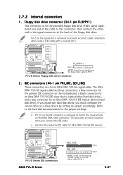
... connection when using a FDD cable with a covered Pin 5. Floppy disk drive connector (34-1 pin FLOPPY1) This connector is removed to PIN 1. 2-27 PVL-D Series ® PVL-D Series IDE connectors ASUS PVL-D Series SEC_IDE PIN 1 PRI_IDE PIN 1 NOTE: Orient the red markings (usually zigzag) on the motherboard, a black connector for an Ultra DMA 100/66...
... connection when using a FDD cable with a covered Pin 5. Floppy disk drive connector (34-1 pin FLOPPY1) This connector is removed to PIN 1. 2-27 PVL-D Series ® PVL-D Series IDE connectors ASUS PVL-D Series SEC_IDE PIN 1 PRI_IDE PIN 1 NOTE: Orient the red markings (usually zigzag) on the motherboard, a black connector for an Ultra DMA 100/66...
User Guide
Page 49
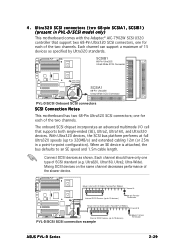
... This motherboard has two 68-Pin Ultra320 SCSI connectors; When an SE device is attached, the bus defaults to 15 devices) PVL-D/SCSI SCSI connection example 68-pin Female Terminator ASUS PVL-D Series 2-29 Connect SCSI devices as specified by Ultra320 standards. Ultra320, Ultra160, Ultra2, Ultra-Wide). Ultra320 SCSI connectors (two 68-pin...
... This motherboard has two 68-Pin Ultra320 SCSI connectors; When an SE device is attached, the bus defaults to 15 devices) PVL-D/SCSI SCSI connection example 68-pin Female Terminator ASUS PVL-D Series 2-29 Connect SCSI devices as specified by Ultra320 standards. Ultra320, Ultra160, Ultra2, Ultra-Wide). Ultra320 SCSI connectors (two 68-pin...

User Guide
Page 51
.../2, REAR_FAN1/2, FRNT_FAN1/2) The fan connectors support cooling fans of 350 mA ~ 740 mA (8.88 W max.) or a total of the connector. COM2 PIN 1 PVL-D Series ® PVL-D Series Serial port connectors The serial port module is for a serial (COM) port. Do not forget to connect the fan cables to a slot opening... Fan connectors REAR_FAN1 GND +12V Rotation FRNT_FAN1 GND +12V Rotation REAR_FAN2 Rotation +12V GND FRNT_FAN2 GND +12V Rotation ASUS PVL-D Series 2-31 Connect the fan cables to the fan connectors on the fan connectors! Connect the serial port module cable to this connector, ...
.../2, REAR_FAN1/2, FRNT_FAN1/2) The fan connectors support cooling fans of 350 mA ~ 740 mA (8.88 W max.) or a total of the connector. COM2 PIN 1 PVL-D Series ® PVL-D Series Serial port connectors The serial port module is for a serial (COM) port. Do not forget to connect the fan cables to a slot opening... Fan connectors REAR_FAN1 GND +12V Rotation FRNT_FAN1 GND +12V Rotation REAR_FAN2 Rotation +12V GND FRNT_FAN2 GND +12V Rotation ASUS PVL-D Series 2-31 Connect the fan cables to the fan connectors on the fan connectors! Connect the serial port module cable to this connector, ...
User Guide
Page 53
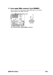
PSUSMB1 PVL-D Series Power supply SMBus connector ASUS PVL-D Series 2-33 Power supply SMBus connector (5-pin PSUSMB1) This connector is for the power supply SMB cable, if your power supply supports the SMBus function. PVL-D Series ® I2C_7_CLK# I2C_7_DATA# NC GND +3.3V Remote Sense 11.
PSUSMB1 PVL-D Series Power supply SMBus connector ASUS PVL-D Series 2-33 Power supply SMBus connector (5-pin PSUSMB1) This connector is for the power supply SMB cable, if your power supply supports the SMBus function. PVL-D Series ® I2C_7_CLK# I2C_7_DATA# NC GND +3.3V Remote Sense 11.

User Guide
Page 55
..., and blinks when the system is in sleep or soft-off the system power. POWERLED+ NC POWERLEDMLED+ MLEDNC +5V GND GND SPKROUT PVL-D Series ® PANEL1 PVL-D Series System panel connector ASUS PVL-D Series HDLED+ HDLEDNMIBTN# GND POWERBTN# GND NC RESETBTN# GND 2-35 The system panel connector is color-coded for easy connection. •...
..., and blinks when the system is in sleep or soft-off the system power. POWERLED+ NC POWERLEDMLED+ MLEDNC +5V GND GND SPKROUT PVL-D Series ® PANEL1 PVL-D Series System panel connector ASUS PVL-D Series HDLED+ HDLEDNMIBTN# GND POWERBTN# GND NC RESETBTN# GND 2-35 The system panel connector is color-coded for easy connection. •...
User Guide
Page 58
Chapter summary 3 3.1 Starting up for the first time 3-1 3.2 Turning off the computer 3-2 ASUS PVL-D Series
Chapter summary 3 3.1 Starting up for the first time 3-1 3.2 Turning off the computer 3-2 ASUS PVL-D Series


