
User Guide
Page 1
Motherboard PVL-D Series PVL-D/SCSI PVL-D/1U
Motherboard PVL-D Series PVL-D/SCSI PVL-D/1U

User Guide
Page 3
Contents Notices vii Safety information viii About this guide ix Typography x PVL-D specifications summary xi Chapter 1: Product introduction 1.1 Welcome 1-1 1.2 Package contents 1-1 1.3 Special features 1-2 1.3.1 Product highlights 1-2 1.3.2 Innovative ASUS features 1-4 Chapter 2: Hardware information 2.1 Before you proceed 2-1 2.2 Motherboard ...18 2.5.4 PCI/PCI-X slots (For PVL-D/SCSI model only) ....... 2-19 2.5.5 ZCR socket (For PVL-D/SCSI model only 2-19 2.5.6 PCI Express x8 slot 2-20 (For PVL-D/SCSI model only) 2.5.7 Mini-PCI socket (For PVL-D/1U model only) ......... 2-20 ...
Contents Notices vii Safety information viii About this guide ix Typography x PVL-D specifications summary xi Chapter 1: Product introduction 1.1 Welcome 1-1 1.2 Package contents 1-1 1.3 Special features 1-2 1.3.1 Product highlights 1-2 1.3.2 Innovative ASUS features 1-4 Chapter 2: Hardware information 2.1 Before you proceed 2-1 2.2 Motherboard ...18 2.5.4 PCI/PCI-X slots (For PVL-D/SCSI model only) ....... 2-19 2.5.5 ZCR socket (For PVL-D/SCSI model only 2-19 2.5.6 PCI Express x8 slot 2-20 (For PVL-D/SCSI model only) 2.5.7 Mini-PCI socket (For PVL-D/1U model only) ......... 2-20 ...

User Guide
Page 5
... configuration 5-24 5.2.7 Selecting the boot drive from a RAID set 5-25 5.2.8 Enabling the WriteCache 5-26 5.3 Global Array Manager 5-26 5.4 Adaptec SCSISelect(TM) Utility 5-27 (PVL-D/SCSI model only) 5.4.1 Configuring the SCSI controller 5-28 5.4.2 Enabling the HostRAID controller 5-28 5.4.3 Creating a RAID 0 set (Stripe 5-29 5.4.4 Creating a RAID 1 set (Mirror 5-33 5.4.5 Creating a RAID 10 set (Stripe+Mirror...
... configuration 5-24 5.2.7 Selecting the boot drive from a RAID set 5-25 5.2.8 Enabling the WriteCache 5-26 5.3 Global Array Manager 5-26 5.4 Adaptec SCSISelect(TM) Utility 5-27 (PVL-D/SCSI model only) 5.4.1 Configuring the SCSI controller 5-28 5.4.2 Enabling the HostRAID controller 5-28 5.4.3 Creating a RAID 0 set (Stripe 5-29 5.4.4 Creating a RAID 1 set (Mirror 5-33 5.4.5 Creating a RAID 10 set (Stripe+Mirror...

User Guide
Page 6
... and utilities installation 6-15 6.4.1 Running the support CD 6-15 6.4.2 Drivers menu 6-15 6.4.3 Management Software menu 6-16 6.4.4 Utilities menu 6-16 6.4.5 Contact information 6-16 Appendix: Block diagrams A.1 PVL-D/SCSI block diagram A-1 A.2 PVL-D/1U block diagram A-2 vi
... and utilities installation 6-15 6.4.1 Running the support CD 6-15 6.4.2 Drivers menu 6-15 6.4.3 Management Software menu 6-16 6.4.4 Utilities menu 6-16 6.4.5 Contact information 6-16 Appendix: Block diagrams A.1 PVL-D/SCSI block diagram A-1 A.2 PVL-D/1U block diagram A-2 vi
User Guide
Page 11
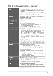
...MHz Dual-channel memory architecture 8 x 240-pin DIMM sockets support registered ECC DDR2-400 memory modules Supports 256 MB up to 16 GB system memory (PVL-D/SCSI model only) 1 x PCI Express™ x8 slot 98P (x8 link, PCI Express 1.0a) 2 x PCI-X 133 MHz/64-bit slots 184P...1 x mini-PCI socket for ASUS® Server Management Board Intel® ICH5R Southbridge supports: - 4 x Ultra DMA 100/66/33 hard disk drives - 2 x SATA-150 with RAID 0, RAID 1 configuration (PVL-D/SCSI model only) Adaptec® AIC-7902W PCI-X Dual U320 SCSI controller supports: - 2 x SCSI channels with PCI Express 1.0a ...
...MHz Dual-channel memory architecture 8 x 240-pin DIMM sockets support registered ECC DDR2-400 memory modules Supports 256 MB up to 16 GB system memory (PVL-D/SCSI model only) 1 x PCI Express™ x8 slot 98P (x8 link, PCI Express 1.0a) 2 x PCI-X 133 MHz/64-bit slots 184P...1 x mini-PCI socket for ASUS® Server Management Board Intel® ICH5R Southbridge supports: - 4 x Ultra DMA 100/66/33 hard disk drives - 2 x SATA-150 with RAID 0, RAID 1 configuration (PVL-D/SCSI model only) Adaptec® AIC-7902W PCI-X Dual U320 SCSI controller supports: - 2 x SCSI channels with PCI Express 1.0a ...

User Guide
Page 12
... Requirement Form Factor Support CD contents ASUS Smart Fan Control ASUS CrashFree BIOS 2 ASUS MyLogo2 AMI BIOS, 8 Mb FWH, Green, PnP, DMI2.0a, ACPI 2.0a SMBIOS 2.3, WfM2.0 1 x PS/2 keyboard port (purple) 1 x PS/2 mouse port (green) 2 x USB 2.0 ports 1 x Serial port 1 x VGA port 2 x LAN (RJ-45) ports 1 x Parallel port (PVL-D/SCSI model only) 1 x Floppy disk drive connector...
... Requirement Form Factor Support CD contents ASUS Smart Fan Control ASUS CrashFree BIOS 2 ASUS MyLogo2 AMI BIOS, 8 Mb FWH, Green, PnP, DMI2.0a, ACPI 2.0a SMBIOS 2.3, WfM2.0 1 x PS/2 keyboard port (purple) 1 x PS/2 mouse port (green) 2 x USB 2.0 ports 1 x Serial port 1 x VGA port 2 x LAN (RJ-45) ports 1 x Parallel port (PVL-D/SCSI model only) 1 x Floppy disk drive connector...

User Guide
Page 15
... is damaged or missing, contact your motherboard package for the following items. Motherboard ASUS PVL-D Series motherboard Cables 2 x Serial ATA signal cables 1 x Serial ATA power cable (dual-plug) 2 x SCSI Ultra320 cables (PVL-D/CSI model only) 80-conductor IDE cable 3-in your package with the list ...below. 1.2 Package contents Check your retailer. Before you for CPUs) I/O shield ASUS motherboard support CD User guide If any of new features...
... is damaged or missing, contact your motherboard package for the following items. Motherboard ASUS PVL-D Series motherboard Cables 2 x Serial ATA signal cables 1 x Serial ATA power cable (dual-plug) 2 x SCSI Ultra320 cables (PVL-D/CSI model only) 80-conductor IDE cable 3-in your package with the list ...below. 1.2 Package contents Check your retailer. Before you for CPUs) I/O shield ASUS motherboard support CD User guide If any of new features...

User Guide
Page 17
... throughput close to -point serial interconnections between devices and allows higher clockspeeds by the Intel® ICH5R. See page 2-28 for details. ASUS PVL-D Series 1-3 See page 2-26 for details. The SATA specification allows for an optional Zero-Channel RAID card, allowing RAID 0 (striping...Serial ATA technology through the Serial ATA interfaces controlled by carrying data in packets. Ultra320 SCSI feature (PVL-D/SCSI model only) The Adaptec® AIC-7902W PCI-X SCSI controller is backward compatible with dual Gigabit LAN controllers and ports to provide a total solution...
... throughput close to -point serial interconnections between devices and allows higher clockspeeds by the Intel® ICH5R. See page 2-28 for details. ASUS PVL-D Series 1-3 See page 2-26 for details. The SATA specification allows for an optional Zero-Channel RAID card, allowing RAID 0 (striping...Serial ATA technology through the Serial ATA interfaces controlled by carrying data in packets. Ultra320 SCSI feature (PVL-D/SCSI model only) The Adaptec® AIC-7902W PCI-X SCSI controller is backward compatible with dual Gigabit LAN controllers and ports to provide a total solution...
User Guide
Page 22
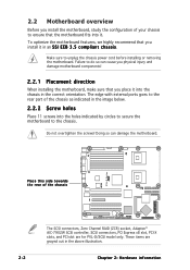
... installing or removing the motherboard. These items are for PVL-D/SCSI model only. Failure to ensure that you install it . PVL-D Series ® Place this side towards the rear of the chassis The SCSI connectors, Zero Channel RAID (ZCR) socket, Adaptec® AIC-7902W SCSI controller, SCSI connectors, PCI Express x8 slot, PCI-X slots, and PCI...
... installing or removing the motherboard. These items are for PVL-D/SCSI model only. Failure to ensure that you install it . PVL-D Series ® Place this side towards the rear of the chassis The SCSI connectors, Zero Channel RAID (ZCR) socket, Adaptec® AIC-7902W SCSI controller, SCSI connectors, PCI Express x8 slot, PCI-X slots, and PCI...

User Guide
Page 28
Zero-Channel RAID socket 5. PCI Express slot 6. Gigabit LAN controller setting (3-pin LAN2_EN1) 8. SCSI controller setting (3-pin SCSI_EN1) 9. PS/2 keyboard port (purple) Page 2-10 2-14 2-19 2-19 2-20 2-20 Page 2-21 2-22 2-22 2-23 2-23 2-24 2-24 2-25 2-25 ... DIMM sockets 3. Mini-PCI socket Jumpers 1. VGA controller setting (3-pin VGA_EN1) 6. PS/2 mouse port (green) 2. Clear RTC RAM (CLRTC1) 2. PCI/PCI-X slots 4. Parallel port (for PVL-D/SCSI model only) 3. USB 2.0 ports 1 and 2 4.
Zero-Channel RAID socket 5. PCI Express slot 6. Gigabit LAN controller setting (3-pin LAN2_EN1) 8. SCSI controller setting (3-pin SCSI_EN1) 9. PS/2 keyboard port (purple) Page 2-10 2-14 2-19 2-19 2-20 2-20 Page 2-21 2-22 2-22 2-23 2-23 2-24 2-24 2-25 2-25 ... DIMM sockets 3. Mini-PCI socket Jumpers 1. VGA controller setting (3-pin VGA_EN1) 6. PS/2 mouse port (green) 2. Clear RTC RAM (CLRTC1) 2. PCI/PCI-X slots 4. Parallel port (for PVL-D/SCSI model only) 3. USB 2.0 ports 1 and 2 4.
User Guide
Page 39
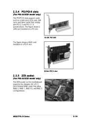
The figure shows a RAID card installed on a PCI-X slot. 32-bit PCI slot 64-bit PCI-X slot 2.5.5 ZCR socket (For PVL-D/SCSI model only) The ZCR socket on a PCI slot. ASUS PVL-D Series 2-19 2.5.4 PCI/PCI-X slots (For PVL-D/SCSI model only) The PCI/PCI-X slots support cards such as a LAN card, SCSI card, USB card, and other cards that allow RAID 0, RAID 1, RAID 10, and RAID 5 configurations. The figure shows a LAN card installed on the motherboard supports the Adaptec AIC-2015 Zero-Channel RAID cards that comply with PCI 2.3 and PCI-X 1.0 specifications.
The figure shows a RAID card installed on a PCI-X slot. 32-bit PCI slot 64-bit PCI-X slot 2.5.5 ZCR socket (For PVL-D/SCSI model only) The ZCR socket on a PCI slot. ASUS PVL-D Series 2-19 2.5.4 PCI/PCI-X slots (For PVL-D/SCSI model only) The PCI/PCI-X slots support cards such as a LAN card, SCSI card, USB card, and other cards that allow RAID 0, RAID 1, RAID 10, and RAID 5 configurations. The figure shows a LAN card installed on the motherboard supports the Adaptec AIC-2015 Zero-Channel RAID cards that comply with PCI 2.3 and PCI-X 1.0 specifications.
User Guide
Page 40
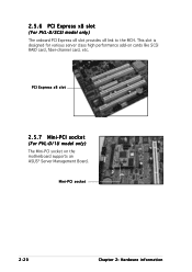
Mini-PCI socket 2-20 Chapter 2: Hardware information 2.5.6 PCI Express x8 slot (For PVL-D/SCSI model only) The onboard PCI Express x8 slot provides x8 link to the MCH. PCI Express x8 slot 2.5.7 Mini-PCI socket (For PVL-D/1U model only) The Mini-PCI socket on cards like SCSI RAID card, fiber-channel card, etc. This slot is designed for various server class high performance add-on the motherboard supports an ASUS® Server Management Board.
Mini-PCI socket 2-20 Chapter 2: Hardware information 2.5.6 PCI Express x8 slot (For PVL-D/SCSI model only) The onboard PCI Express x8 slot provides x8 link to the MCH. PCI Express x8 slot 2.5.7 Mini-PCI socket (For PVL-D/1U model only) The Mini-PCI socket on cards like SCSI RAID card, fiber-channel card, etc. This slot is designed for various server class high performance add-on the motherboard supports an ASUS® Server Management Board.
User Guide
Page 41
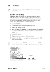
To erase the RTC RAM: 1. Keep the cap on CLRTC jumper default position. PVL-D Series ® PVL-D Series Clear RTC RAM CLRTC1 21 32 Normal Clear CMOS (Default) ASUS PVL-D Series 2-21 Clear RTC RAM (CLRTC1) This jumper allows you to pins 1-2. 4. Except when clearing the RTC RAM, never remove the...Real Time Clock (RTC) RAM in CMOS. Removing the cap will cause system boot failure! The onboard button cell battery powers the RAM data in PVL-D/SCSI model. 1. Turn OFF the computer and unplug the power cord. 2. Remove the onboard battery. 3. Plug the power cord and turn ON the ...
To erase the RTC RAM: 1. Keep the cap on CLRTC jumper default position. PVL-D Series ® PVL-D Series Clear RTC RAM CLRTC1 21 32 Normal Clear CMOS (Default) ASUS PVL-D Series 2-21 Clear RTC RAM (CLRTC1) This jumper allows you to pins 1-2. 4. Except when clearing the RTC RAM, never remove the...Real Time Clock (RTC) RAM in CMOS. Removing the cap will cause system boot failure! The onboard button cell battery powers the RAM data in PVL-D/SCSI model. 1. Turn OFF the computer and unplug the power cord. 2. Remove the onboard battery. 3. Plug the power cord and turn ON the ...
User Guide
Page 45
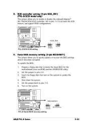
...(xxxx-xxx.ROM) and the AFUDOS.EXE utility. 2. PVL-D Series ® RECOVERY1 12 23 Normal BIOS Recovery (Default) PVL-D Series BIOS recovery setting ASUS PVL-D Series 2-25 SCSI controller setting (3-pin SCSI_EN1) (PVL-D/SCSI model only) This jumper allows you to enable or disable... the onboard Adaptec® AIC-7902W SCSI U320 controller. Shut down the system. 5....
...(xxxx-xxx.ROM) and the AFUDOS.EXE utility. 2. PVL-D Series ® RECOVERY1 12 23 Normal BIOS Recovery (Default) PVL-D Series BIOS recovery setting ASUS PVL-D Series 2-25 SCSI controller setting (3-pin SCSI_EN1) (PVL-D/SCSI model only) This jumper allows you to enable or disable... the onboard Adaptec® AIC-7902W SCSI U320 controller. Shut down the system. 5....

User Guide
Page 46
... is for a PS/2 keyboard. 2-26 Chapter 2: Hardware information 2.7 Connectors 2.7.1 Rear panel connectors 1 2 7 6 5 4 3 1 . This 9-pin communication port is for pointing devices or other devices. (present in PVL-D/SCSI model only) 3 . P S / 2 m o u s e p o r t ( g r e e n ) .
... is for a PS/2 keyboard. 2-26 Chapter 2: Hardware information 2.7 Connectors 2.7.1 Rear panel connectors 1 2 7 6 5 4 3 1 . This 9-pin communication port is for pointing devices or other devices. (present in PVL-D/SCSI model only) 3 . P S / 2 m o u s e p o r t ( g r e e n ) .
User Guide
Page 49
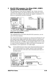
... slower device. 68-pin Internal SCSI Cable (Twisted-Pair Ribbon) Channel A PVL-D Series ® Internal SCSI Devices (up to 15 devices) 68-pin Female Terminator 68-pin Internal SCSI Cable (Twisted-Pair Ribbon) Channel B Internal SCSI Devices (up to 15 devices) PVL-D/SCSI SCSI connection example 68-pin Female Terminator ASUS PVL-D Series 2-29 4 . Ultra320 SCSI connectors (two 68-pin SCSIA1...
... slower device. 68-pin Internal SCSI Cable (Twisted-Pair Ribbon) Channel A PVL-D Series ® Internal SCSI Devices (up to 15 devices) 68-pin Female Terminator 68-pin Internal SCSI Cable (Twisted-Pair Ribbon) Channel B Internal SCSI Devices (up to 15 devices) PVL-D/SCSI SCSI connection example 68-pin Female Terminator ASUS PVL-D Series 2-29 4 . Ultra320 SCSI connectors (two 68-pin SCSIA1...
User Guide
Page 50
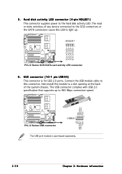
... at the back of the system chassis. Connect the USB module cable to this LED to light up to the hard disk activity LED. HDLED1 1 PVL-D Series SCSI/SATA card activity LED connector 6. This USB connector complies with USB 2.0 specification that supports up . USB connector (10-1 pin USB34) This connector is purchased...
... at the back of the system chassis. Connect the USB module cable to this LED to light up to the hard disk activity LED. HDLED1 1 PVL-D Series SCSI/SATA card activity LED connector 6. This USB connector complies with USB 2.0 specification that supports up . USB connector (10-1 pin USB34) This connector is purchased...

User Guide
Page 59
... power connector at the back of the system chassis. 4. While the tests are off. 3. Connect the power cord to enter the BIOS Setup. Monitor b. External SCSI devices (starting with "green" standards or if it has a "power standby" feature, the monitor LED may have failed a power-on . After applying power, the system...) or additional messages appear on self tests or POST. Connect the power cord to a power outlet that all the connections, replace the system case cover. 2. ASUS PVL-D Series 3-1 Follow the instructions in the following order: a.
... power connector at the back of the system chassis. 4. While the tests are off. 3. Connect the power cord to enter the BIOS Setup. Monitor b. External SCSI devices (starting with "green" standards or if it has a "power standby" feature, the monitor LED may have failed a power-on . After applying power, the system...) or additional messages appear on self tests or POST. Connect the power cord to a power outlet that all the connections, replace the system case cover. 2. ASUS PVL-D Series 3-1 Follow the instructions in the following order: a.
User Guide
Page 65
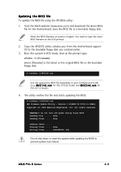
..., Inc. All rights reserved. ASUS PVL-D Series 4-3 Visit the ASUS website (www.asus.com) and download the latest BIOS file for PVL-D/1U model). 4. Write the BIOS filename on your motherboard model (e.g. A:\>afudos /iI8021A0.rom Use the appropriate BIOS file depending on a piece of paper. WARNING!! done Advance Check ...... Erasing flash ...... r o m for PVL-D/SCSI model, and I 8 0 2 1 A 0 . Save...
..., Inc. All rights reserved. ASUS PVL-D Series 4-3 Visit the ASUS website (www.asus.com) and download the latest BIOS file for PVL-D/1U model). 4. Write the BIOS filename on your motherboard model (e.g. A:\>afudos /iI8021A0.rom Use the appropriate BIOS file depending on a piece of paper. WARNING!! done Advance Check ...... Erasing flash ...... r o m for PVL-D/SCSI model, and I 8 0 2 1 A 0 . Save...
User Guide
Page 67
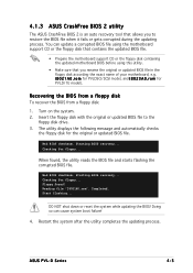
...NOT shut down or reset the system while updating the BIOS! Starting BIOS recovery... When found ! Checking for PVLD/1U model). Start flashing... ASUS PVL-D Series 4-5 You can cause system boot failure! 4. Recovering the BIOS from a floppy disk To recover the BIOS from a floppy disk: ...0 2 3 A 0 . r o m for floppy... Floppy found , the utility reads the BIOS file and starts flashing the corrupted BIOS file. r o m for PVLDSCI/SCSI model, and I 8 0 2 1 A 0 . Insert the floppy disk with the original or updated BIOS file to restore the BIOS file when it fails or gets corrupted during...
...NOT shut down or reset the system while updating the BIOS! Starting BIOS recovery... When found ! Checking for PVLD/1U model). Start flashing... ASUS PVL-D Series 4-5 You can cause system boot failure! 4. Recovering the BIOS from a floppy disk To recover the BIOS from a floppy disk: ...0 2 3 A 0 . r o m for floppy... Floppy found , the utility reads the BIOS file and starts flashing the corrupted BIOS file. r o m for PVLDSCI/SCSI model, and I 8 0 2 1 A 0 . Insert the floppy disk with the original or updated BIOS file to restore the BIOS file when it fails or gets corrupted during...