
Users Manual English
Page 3
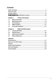
......iv About this guide...v Package contents...vii PRIME B760M-PLUS specifications summary viii Chapter 1: Product Introduction 1.1 Before you proceed 1-1 1.2 Motherboard layout 1-2 1.3 CPU installation 1-9 1.4 DIMM installation 1-11 1.5 M.2 module installation 1-13 Chapter 2: BIOS and RAID Support 2.1 Knowing UEFI BIOS 2-1 2.2 ASUS EZ Flash 3 2-2 2.3 ASUS CrashFree BIOS 3 2-3 2.4 RAID configurations 2-4 Appendix General Notices...A-1 Notices for non Wi-Fi model A-4 Warranty...A-6 ASUS contact information A-8 Service and Support A-8 Product Register...A-8 iii
......iv About this guide...v Package contents...vii PRIME B760M-PLUS specifications summary viii Chapter 1: Product Introduction 1.1 Before you proceed 1-1 1.2 Motherboard layout 1-2 1.3 CPU installation 1-9 1.4 DIMM installation 1-11 1.5 M.2 module installation 1-13 Chapter 2: BIOS and RAID Support 2.1 Knowing UEFI BIOS 2-1 2.2 ASUS EZ Flash 3 2-2 2.3 ASUS CrashFree BIOS 3 2-3 2.4 RAID configurations 2-4 Appendix General Notices...A-1 Notices for non Wi-Fi model A-4 Warranty...A-6 ASUS contact information A-8 Service and Support A-8 Product Register...A-8 iii
Users Manual English
Page 4
... unplugged. • Seek professional assistance before using , contact your local power company. • If the power supply is broken, do not try to chemical burns, perforation of the electrical outlet you add a device. • Before connecting or removing signal cables from the motherboard, ensure that the power cables for the devices are unplugged before the signal cables are not damaged. Severe burns can...
... unplugged. • Seek professional assistance before using , contact your local power company. • If the power supply is broken, do not try to chemical burns, perforation of the electrical outlet you add a device. • Before connecting or removing signal cables from the motherboard, ensure that the power cables for the devices are unplugged before the signal cables are not damaged. Severe burns can...

Users Manual English
Page 5
... need when installing and configuring the motherboard. v About this guide is organized This guide contains the following sources for additional information and for each part of the standard package. Where to find more information Refer to boot into the BIOS, upgrade BIOS using the EZ Flash Utility and support on ASUS hardware and software products. 2. These documents are not part of the motherboard. • Chapter 2: BIOS and RAID Support This chapter...
... need when installing and configuring the motherboard. v About this guide is organized This guide contains the following sources for additional information and for each part of the standard package. Where to find more information Refer to boot into the BIOS, upgrade BIOS using the EZ Flash Utility and support on ASUS hardware and software products. 2. These documents are not part of the motherboard. • Chapter 2: BIOS and RAID Support This chapter...

Users Manual English
Page 6
Motherboard Installation Guide Please visit https://www.asus.com/support for more information on the RAID Configuration Guide. vi 3. RAID Configuration Guide Please visit https://www.asus.com/support for more information on downloading and installing drivers and utilities for more information on the Motherboard Installation Guide. 4. Driver and Utilities FAQ Please visit https://www.asus.com/support for your motherboard. 5.
Motherboard Installation Guide Please visit https://www.asus.com/support for more information on the RAID Configuration Guide. vi 3. RAID Configuration Guide Please visit https://www.asus.com/support for more information on downloading and installing drivers and utilities for more information on the Motherboard Installation Guide. 4. Driver and Utilities FAQ Please visit https://www.asus.com/support for your motherboard. 5.

Users Manual English
Page 7
... to help you MUST follow to complete a task. Conventions used throughout this user guide. Package contents Check your motherboard package for M.2 SSD 1 x Quick start guide • If any of the following items. Motherboard Cables Miscellaneous Documentation 1 x PRIME B760M-PLUS motherboard 2 x SATA 6Gb/s cables 1 x M.2 Rubber package 1 x Screw package for the following symbols used in the Package contents list above are purchased separately and do not come bundled...
... to help you MUST follow to complete a task. Conventions used throughout this user guide. Package contents Check your motherboard package for M.2 SSD 1 x Quick start guide • If any of the following items. Motherboard Cables Miscellaneous Documentation 1 x PRIME B760M-PLUS motherboard 2 x SATA 6Gb/s cables 1 x M.2 Rubber package 1 x Screw package for the following symbols used in the Package contents list above are purchased separately and do not come bundled...
Users Manual English
Page 8
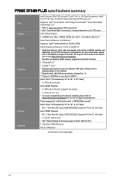
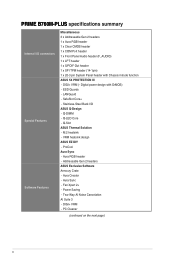
... function. 1 x DisplayPort** 1 x HDMI™ port*** * Graphics specifications may vary between CPU types. PRIME B760M-PLUS specifications summary CPU Chipset Memory Graphics Expansion Slots Storage Ethernet Intel® Socket LGA1700 for Intel® Core™ 14th & 13th Gen Processors, Intel® Core™ 12th Gen, Pentium® Gold and Celeron® Processors* Supports Intel® Turbo Boost Technology 2.0 and Intel® Turbo Boost Max Technology 3.0** * Refer to www.asus.com for CPU support list. ** Intel® Turbo Boost Max Technology 3.0 support depends on...
... function. 1 x DisplayPort** 1 x HDMI™ port*** * Graphics specifications may vary between CPU types. PRIME B760M-PLUS specifications summary CPU Chipset Memory Graphics Expansion Slots Storage Ethernet Intel® Socket LGA1700 for Intel® Core™ 14th & 13th Gen Processors, Intel® Core™ 12th Gen, Pentium® Gold and Celeron® Processors* Supports Intel® Turbo Boost Technology 2.0 and Intel® Turbo Boost Max Technology 3.0** * Refer to www.asus.com for CPU support list. ** Intel® Turbo Boost Max Technology 3.0 support depends on...
Users Manual English
Page 9
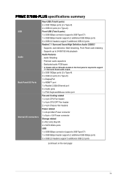
... Audio jacks 1 x PS/2 Keyboard/Mouse combo port Fan and Cooling related 1 x 4-pin CPU Fan header 1 x 4-pin CPU OPT Fan header 2 x 4-pin Chassis Fan headers Power related 1 x 24-pin Main Power connector 1 x 8-pin +12V Power connector Storage related 2 x M.2 slots (Key M) 4 x SATA 6Gb/s ports USB 1 x USB 5Gbps connector (supports USB Type-C®) 1 x USB 5Gbps header supports 2 additional USB 5Gbps ports 3 x USB 2.0 headers support 5 additional USB 2.0 ports (continued on the next page) ix Dedicated audio PCB layers * A chassis with an HD audio module in the front panel is required to 24-Bit...
... Audio jacks 1 x PS/2 Keyboard/Mouse combo port Fan and Cooling related 1 x 4-pin CPU Fan header 1 x 4-pin CPU OPT Fan header 2 x 4-pin Chassis Fan headers Power related 1 x 24-pin Main Power connector 1 x 8-pin +12V Power connector Storage related 2 x M.2 slots (Key M) 4 x SATA 6Gb/s ports USB 1 x USB 5Gbps connector (supports USB Type-C®) 1 x USB 5Gbps header supports 2 additional USB 5Gbps ports 3 x USB 2.0 headers support 5 additional USB 2.0 ports (continued on the next page) ix Dedicated audio PCB layers * A chassis with an HD audio module in the front panel is required to 24-Bit...
Users Manual English
Page 10
... Special Features Software Features Miscellaneous 3 x Addressable Gen 2 headers 1 x Aura RGB header 1 x Clear CMOS header 1 x COM Port header 1 x Front Panel Audio header (F_AUDIO) 1 x LPT header 1 x S/PDIF Out header 1 x SPI TPM header (14-1pin) 1 x 20-3 pin System Panel header with DrMOS) - Q-Slot ASUS Thermal Solution - DIGI+ VRM - ESD Guards - Q-DIMM - PRIME B760M-PLUS specifications summary Internal I /O ASUS Q-Design - VRM heatsink design ASUS EZ DIY - DIGI+ VRM (- Digital power design with Chassis intrude function ASUS 5X PROTECTION III - Q-LED Core - Two-Way...
... Special Features Software Features Miscellaneous 3 x Addressable Gen 2 headers 1 x Aura RGB header 1 x Clear CMOS header 1 x COM Port header 1 x Front Panel Audio header (F_AUDIO) 1 x LPT header 1 x S/PDIF Out header 1 x SPI TPM header (14-1pin) 1 x 20-3 pin System Panel header with DrMOS) - Q-Slot ASUS Thermal Solution - DIGI+ VRM - ESD Guards - Q-DIMM - PRIME B760M-PLUS specifications summary Internal I /O ASUS Q-Design - VRM heatsink design ASUS EZ DIY - DIGI+ VRM (- Digital power design with Chassis intrude function ASUS 5X PROTECTION III - Q-LED Core - Two-Way...
Users Manual English
Page 11
Please refer to change without notice. ASUS UEFI BIOS EZ Mode 128 Mb Flash ROM, UEFI AMI BIOS PB760MP.CAP WOL by PME, PXE Windows® 11 Windows® 10 64-bit micro-ATX Form Factor 9.6 inch x 9.6 inch ( 24.4 cm x 24.4 cm ) Specifications are subject to the ASUS website for the latest specifications. ASUS EZ Flash 3 - xi PRIME B760M-PLUS specifications summary Software Features BIOS BIOS CAP Filename Manageability Operating System Form Factor ASUS CPU-Z Norton 360 Deluxe (60 Days Free Trial) WinRAR (40 Days Free Trial) UEFI BIOS ASUS EZ DIY - ASUS CrashFree BIOS 3 -
Please refer to change without notice. ASUS UEFI BIOS EZ Mode 128 Mb Flash ROM, UEFI AMI BIOS PB760MP.CAP WOL by PME, PXE Windows® 11 Windows® 10 64-bit micro-ATX Form Factor 9.6 inch x 9.6 inch ( 24.4 cm x 24.4 cm ) Specifications are subject to the ASUS website for the latest specifications. ASUS EZ Flash 3 - xi PRIME B760M-PLUS specifications summary Software Features BIOS BIOS CAP Filename Manageability Operating System Form Factor ASUS CPU-Z Norton 360 Deluxe (60 Days Free Trial) WinRAR (40 Days Free Trial) UEFI BIOS ASUS EZ DIY - ASUS CrashFree BIOS 3 -
Users Manual English
Page 13
... that the power supply is switched off or the power cord is only available on the location of the following precautions before you install motherboard components or change any motherboard settings. • Unplug the power cord from the wall socket before touching any component. • Before handling components, use a grounded wrist strap or touch a safely grounded object or a metal object, such as the power supply case, to...
... that the power supply is switched off or the power cord is only available on the location of the following precautions before you install motherboard components or change any motherboard settings. • Unplug the power cord from the wall socket before touching any component. • Before handling components, use a grounded wrist strap or touch a safely grounded object or a metal object, such as the power supply case, to...

Users Manual English
Page 14
... 2_2 TPM SATA6G_34 M.2_2(SOCKET3) 24.4cm(9.6in) 11 5 9 8 7 18 6 1.2.1 Layout contents 1. For more details, refer to DIMM installation. 1-2 Chapter 1: Product Introduction For more details, refer to CPU installation. 2. CPU socket The motherboard comes with Dual Inline Memory Modules (DIMM) slots designed for Intel® Core™ 14th & 13th Gen Processors, Intel® Core™ 12th Gen, Pentium® Gold and Celeron®...
... 2_2 TPM SATA6G_34 M.2_2(SOCKET3) 24.4cm(9.6in) 11 5 9 8 7 18 6 1.2.1 Layout contents 1. For more details, refer to DIMM installation. 1-2 Chapter 1: Product Introduction For more details, refer to CPU installation. 2. CPU socket The motherboard comes with Dual Inline Memory Modules (DIMM) slots designed for Intel® Core™ 14th & 13th Gen Processors, Intel® Core™ 12th Gen, Pentium® Gold and Celeron®...

Users Manual English
Page 15
... Storage Technology supports SATA RAID 0/1/5/10. 7. Expansion slots This motherboard supports one PCIe x16 graphics card, one PCIe x16 (supporting x4 mode) and one orientation. Power connectors These Power connectors allow you to ensure the system stability. 6. The system may become unstable or may not boot up to connect a USB 5Gbps Type-C® module for an additional USB 5Gbps Type-C® port. SATA 6Gb/s ports The SATA 6Gb/s ports allow you to 5 Gb/s. 3. M.2 slots (Key M) The M.2 slots allow you use two high-end PCI Express x16 cards...
... Storage Technology supports SATA RAID 0/1/5/10. 7. Expansion slots This motherboard supports one PCIe x16 graphics card, one PCIe x16 (supporting x4 mode) and one orientation. Power connectors These Power connectors allow you to ensure the system stability. 6. The system may become unstable or may not boot up to connect a USB 5Gbps Type-C® module for an additional USB 5Gbps Type-C® port. SATA 6Gb/s ports The SATA 6Gb/s ports allow you to 5 Gb/s. 3. M.2 slots (Key M) The M.2 slots allow you use two high-end PCI Express x16 cards...

Users Manual English
Page 16
... the power supply. Before you install or remove any component, ensure that the power supply is switched off or the power cord is detached from the power supply. Doing so will only light up to the motherboard, peripherals, or components. Failure to do so may cause severe damage to connect a USB 5Gbps module for additional USB 2.0 ports. The USB 5Gbps header provides data transfer speeds of 500 LEDs. • Actual lighting and...
... the power supply. Before you install or remove any component, ensure that the power supply is switched off or the power cord is detached from the power supply. Doing so will only light up to the motherboard, peripherals, or components. Failure to do so may cause severe damage to connect a USB 5Gbps module for additional USB 2.0 ports. The USB 5Gbps header provides data transfer speeds of 500 LEDs. • Actual lighting and...
Users Manual English
Page 17
... the front panel audio I /O module that supports HD Audio. Turn OFF the computer and unplug the power cord. 2. After clearing the CMOS, reinstall the button cell battery. 14. 13. COM Port header The COM (Serial) Port connector allows you to a slot opening on IBM PC-compatible computers. Short-circuit pin 1-2 with a metal object or jumper cap for a chassis-mounted front panel audio I /O module cable to this connector, then install the module to connect a COM port module. COM PIN 1 DCD...
... the front panel audio I /O module that supports HD Audio. Turn OFF the computer and unplug the power cord. 2. After clearing the CMOS, reinstall the button cell battery. 14. 13. COM Port header The COM (Serial) Port connector allows you to a slot opening on IBM PC-compatible computers. Short-circuit pin 1-2 with a metal object or jumper cap for a chassis-mounted front panel audio I /O module cable to this connector, then install the module to connect a COM port module. COM PIN 1 DCD...

Users Manual English
Page 18
... system beeps and warnings. • Power Button/Soft-off mode (depending on the operating system settings). • Reset button header (RESET) The 2-pin header allows you to this header in sleep mode. • Storage Device Activity LED header (HDD_LED) The 2-pin header allows you turn on card. • System Warning Speaker header (SPEAKER) The 4-pin header allows you to reboot the system. You can assign a different function to connect the chassis-mounted intrusion detection sensor or switch. The System Power LED lights up...
... system beeps and warnings. • Power Button/Soft-off mode (depending on the operating system settings). • Reset button header (RESET) The 2-pin header allows you to this header in sleep mode. • Storage Device Activity LED header (HDD_LED) The 2-pin header allows you turn on card. • System Warning Speaker header (SPEAKER) The 4-pin header allows you to reboot the system. You can assign a different function to connect the chassis-mounted intrusion detection sensor or switch. The System Power LED lights up...
Users Manual English
Page 23
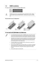
...-marked value. • For system stability, use a more efficient memory cooling system to support a full memory load or overclocking condition. • Always install the DIMMS with the vendor to the DDR5 slot. 1.4 DIMM installation The figure illustrates the location of the DDR5 DIMM sockets A DDR5 memory module is the standard way of accessing information from a memory module. Under the default state, some memory modules for the dual-channel configuration.
...-marked value. • For system stability, use a more efficient memory cooling system to support a full memory load or overclocking condition. • Always install the DIMMS with the vendor to the DDR5 slot. 1.4 DIMM installation The figure illustrates the location of the DDR5 DIMM sockets A DDR5 memory module is the standard way of accessing information from a memory module. Under the default state, some memory modules for the dual-channel configuration.
Users Manual English
Page 29
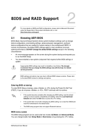
... system fails to boot after changing any BIOS setting, try to clear the CMOS and reset the motherboard to the default value. • The BIOS setup program does not support Bluetooth devices. BIOS menu screen The BIOS Setup program can change modes from Setup Mode in the motherboard CMOS. BIOS settings and options may result to different BIOS release versions. Motherboard User Manual 2-1 Inappropriate BIOS settings may vary due to instability or boot failure. Select the Load Optimized Defaults item under the Support tab of a trained service personnel. Please refer...
... system fails to boot after changing any BIOS setting, try to clear the CMOS and reset the motherboard to the default value. • The BIOS setup program does not support Bluetooth devices. BIOS menu screen The BIOS Setup program can change modes from Setup Mode in the motherboard CMOS. BIOS settings and options may result to different BIOS release versions. Motherboard User Manual 2-1 Inappropriate BIOS settings may vary due to instability or boot failure. Select the Load Optimized Defaults item under the Support tab of a trained service personnel. Please refer...
Users Manual English
Page 30
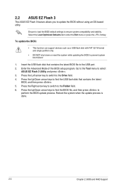
... updating the BIOS to update the BIOS without using an OS‑based utility. Reboot the system when the update process is done. 2-2 Chapter 2: BIOS and RAID Support Press the Up/Down arrow keys to find the USB flash disk that contains the latest BIOS file to perform the BIOS update process. Enter the Advanced Mode of the BIOS setup program. Go to the Tool menu to the Folder field. 6. Select the Load Optimized Defaults...
... updating the BIOS to update the BIOS without using an OS‑based utility. Reboot the system when the update process is done. 2-2 Chapter 2: BIOS and RAID Support Press the Up/Down arrow keys to find the USB flash disk that contains the latest BIOS file to perform the BIOS update process. Enter the Advanced Mode of the BIOS setup program. Go to the Tool menu to the Folder field. 6. Select the Load Optimized Defaults...
Users Manual English
Page 31
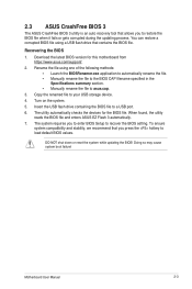
... updating the BIOS! Rename the file using a USB flash drive that allows you to load default BIOS values. Copy the renamed file to a USB port. 6. The system requires you press the hotkey to restore the BIOS file when it fails or gets corrupted during the updating process. When found, the utility reads the BIOS file and enters ASUS EZ Flash 3 automatically. 7. Recovering the BIOS 1. Motherboard User Manual 2-3 2.3 ASUS CrashFree BIOS 3 The ASUS CrashFree BIOS 3 utility is an auto recovery tool that contains the BIOS file...
... updating the BIOS! Rename the file using a USB flash drive that allows you to load default BIOS values. Copy the renamed file to a USB port. 6. The system requires you press the hotkey to restore the BIOS file when it fails or gets corrupted during the updating process. When found, the utility reads the BIOS file and enters ASUS EZ Flash 3 automatically. 7. Recovering the BIOS 1. Motherboard User Manual 2-3 2.3 ASUS CrashFree BIOS 3 The ASUS CrashFree BIOS 3 utility is an auto recovery tool that contains the BIOS file...

Users Manual English
Page 32
..., relational database applications, enterprise resource planning, and other drive. Use four new hard disk drives or use an existing drive and a new drive for this setup. 2-4 Chapter 2: BIOS and RAID Support Two hard disks perform the same work as it contains a complete copy of the same size or larger than the existing drive. RAID 10 is required for this setup. 2.4 RAID configurations The motherboard supports RAID configurations. RAID 1 (Data mirroring) copies and maintains an identical image...
..., relational database applications, enterprise resource planning, and other drive. Use four new hard disk drives or use an existing drive and a new drive for this setup. 2-4 Chapter 2: BIOS and RAID Support Two hard disks perform the same work as it contains a complete copy of the same size or larger than the existing drive. RAID 10 is required for this setup. 2.4 RAID configurations The motherboard supports RAID configurations. RAID 1 (Data mirroring) copies and maintains an identical image...


