
Users Manual English
Page 2
SPECIFICATIONS AND INFORMATION CONTAINED IN THIS MANUAL ARE FURNISHED FOR INFORMATIONAL USE ONLY, AND ARE SUBJECT TO CHANGE AT ANY TIME WITHOUT NOTICE, AND SHOULD NOT BE CONSTRUED AS A COMMITMENT BY ASUS. ASUS ASSUMES NO RESPONSIBILITY OR LIABILITY FOR ANY ERRORS OR INACCURACIES THAT MAY APPEAR IN THIS MANUAL, INCLUDING THE PRODUCTS AND SOFTWARE DESCRIBED IN IT. This offer is...
SPECIFICATIONS AND INFORMATION CONTAINED IN THIS MANUAL ARE FURNISHED FOR INFORMATIONAL USE ONLY, AND ARE SUBJECT TO CHANGE AT ANY TIME WITHOUT NOTICE, AND SHOULD NOT BE CONSTRUED AS A COMMITMENT BY ASUS. ASUS ASSUMES NO RESPONSIBILITY OR LIABILITY FOR ANY ERRORS OR INACCURACIES THAT MAY APPEAR IN THIS MANUAL, INCLUDING THE PRODUCTS AND SOFTWARE DESCRIBED IN IT. This offer is...
Users Manual English
Page 3
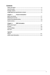
Contents Safety information...iv About this guide...iv Package contents...vi PRIME B360-PLUS specifications summary vi Chapter 1: Product introduction Before you proceed 1-1 Motherboard overview 1-1 Central Processing Unit (CPU 1-8 System memory...1-9 Chapter 2: BIOS information BIOS setup program 2-1 EZ Mode...2-2 Advanced Mode...2-3 Exit menu...2-4 Appendix Notices...A-1 ASUS contact information A-4 iii
Contents Safety information...iv About this guide...iv Package contents...vi PRIME B360-PLUS specifications summary vi Chapter 1: Product introduction Before you proceed 1-1 Motherboard overview 1-1 Central Processing Unit (CPU 1-8 System memory...1-9 Chapter 2: BIOS information BIOS setup program 2-1 EZ Mode...2-2 Advanced Mode...2-3 Exit menu...2-4 Appendix Notices...A-1 ASUS contact information A-4 iii

Users Manual English
Page 4
... features of the switches, jumpers, and connectors on a stable surface. • If you detect any area where it supports. How this guide This user guide contains the information you add a device. • Before connecting or removing signal cables from the motherboard, ensure that all power cables from the existing system before using , contact your local power company. • If the power supply is set to the correct voltage in any...
... features of the switches, jumpers, and connectors on a stable surface. • If you detect any area where it supports. How this guide This user guide contains the information you add a device. • Before connecting or removing signal cables from the motherboard, ensure that all power cables from the existing system before using , contact your local power company. • If the power supply is set to the correct voltage in any...
Users Manual English
Page 6
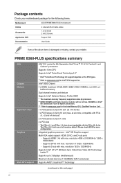
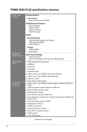
... mode as default. PRIME B360-PLUS specifications summary CPU Chipset Memory Expansion slots Graphics Multi-GPU support LGA1151 socket for 8th Generation Intel® Core™ i7/ i5/ i3, Pentium®, and Celeron® processors Supports 14nm CPU Supports Intel® Turbo Boost Technology 2.0* * Intel® Turbo Boost Technology 2.0 support depends on the CPU types. ** Refer to www.asus.com for more configuration. Please check BIOS for the latest Memory QVL (Qualified Vendors List). 1 x PCI Express 3.0/2.0 x16 slot (at x4 mode, compatible with PCIe...
... mode as default. PRIME B360-PLUS specifications summary CPU Chipset Memory Expansion slots Graphics Multi-GPU support LGA1151 socket for 8th Generation Intel® Core™ i7/ i5/ i3, Pentium®, and Celeron® processors Supports 14nm CPU Supports Intel® Turbo Boost Technology 2.0* * Intel® Turbo Boost Technology 2.0 support depends on the CPU types. ** Refer to www.asus.com for more configuration. Please check BIOS for the latest Memory QVL (Qualified Vendors List). 1 x PCI Express 3.0/2.0 x16 slot (at x4 mode, compatible with PCIe...
Users Manual English
Page 7
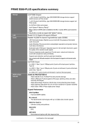
...™ Memory Ready** * When a device in the front panel to guard the quality of the sensitive audio signals - The latest transfer technologies with M Key, type 2242/2260/2280 storage devices support (x4 PCIe mode) - 6 x SATA 6.0 Gb/s ports (gray) - PRIME B360-PLUS specifications summary Storage LAN Audio USB ASUS unique features Intel® B360 Chipset - 1 x M.2 Socket 3 with M Key, type 2242/2260/2280 storage devices support (SATA mode & x2 PCIe mode)* - 1 x M.2 Socket 3 with up to 5Gbps) ports (2 ports at mid-board; 2 ports at the back panel, blue, Type A) - 6 x USB 2.0/1.1 ports...
...™ Memory Ready** * When a device in the front panel to guard the quality of the sensitive audio signals - The latest transfer technologies with M Key, type 2242/2260/2280 storage devices support (x4 PCIe mode) - 6 x SATA 6.0 Gb/s ports (gray) - PRIME B360-PLUS specifications summary Storage LAN Audio USB ASUS unique features Intel® B360 Chipset - 1 x M.2 Socket 3 with M Key, type 2242/2260/2280 storage devices support (SATA mode & x2 PCIe mode)* - 1 x M.2 Socket 3 with up to 5Gbps) ports (2 ports at mid-board; 2 ports at the back panel, blue, Type A) - 6 x USB 2.0/1.1 ports...
Users Manual English
Page 8
... DIY UEFI BIOS EZ Mode - PRIME B360-PLUS specifications summary ASUS unique features ASUS quiet thermal solution Back panel I/O ports Internal I /O ports 1 x USB 3.1 Gen 1 (up to 5Gbps) connector supports additional 2 USB ports (19-pin) 1 x USB 2.0 connector supports additional 2 USB ports 6 x SATA 6.0 Gb/s connectors (gray) 2 x M.2 Socket 3 (for M Key) 1 x 4-pin CPU Fan connector (PWM mode) 2 x 4-pin Chassis Fan connectors for 3-pin (DC mode) and 4-pin (PWM mode) coolers control 1 x Front panel audio connector (AAFP) 1 x System panel connector 1 x S/PDIF out connector 1 x 24-pin EATX power...
... DIY UEFI BIOS EZ Mode - PRIME B360-PLUS specifications summary ASUS unique features ASUS quiet thermal solution Back panel I/O ports Internal I /O ports 1 x USB 3.1 Gen 1 (up to 5Gbps) connector supports additional 2 USB ports (19-pin) 1 x USB 2.0 connector supports additional 2 USB ports 6 x SATA 6.0 Gb/s connectors (gray) 2 x M.2 Socket 3 (for M Key) 1 x 4-pin CPU Fan connector (PWM mode) 2 x 4-pin Chassis Fan connectors for 3-pin (DC mode) and 4-pin (PWM mode) coolers control 1 x Front panel audio connector (AAFP) 1 x System panel connector 1 x S/PDIF out connector 1 x 24-pin EATX power...
Users Manual English
Page 9
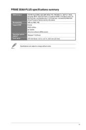
ix PRIME B360-PLUS specifications summary BIOS features Manageability Support DVD Operating system support Form factor 128 Mb Flash ROM, UEFI AMI BIOS, PnP, SM BIOS 3.1, ACPI 6.1, Multilanguage BIOS, ASUS EZ Flash 3, CrashFree BIOS 3, F6 Qfan Control, F3 My Favorites, Last Modified log, F12 PrintScreen, and ASUS DRAM SPD (Serial Presence Detect) memory information WOL by PME, PXE Drivers ASUS utilities EZ Update Anti-virus software (OEM version) Windows® 10 (64-bit) ATX form factor: 12.0 in . (30.5 cm x 22.1cm) Specifications are subject to change without notice. x 8.7 in .
ix PRIME B360-PLUS specifications summary BIOS features Manageability Support DVD Operating system support Form factor 128 Mb Flash ROM, UEFI AMI BIOS, PnP, SM BIOS 3.1, ACPI 6.1, Multilanguage BIOS, ASUS EZ Flash 3, CrashFree BIOS 3, F6 Qfan Control, F3 My Favorites, Last Modified log, F12 PrintScreen, and ASUS DRAM SPD (Serial Presence Detect) memory information WOL by PME, PXE Drivers ASUS utilities EZ Update Anti-virus software (OEM version) Windows® 10 (64-bit) ATX form factor: 12.0 in . (30.5 cm x 22.1cm) Specifications are subject to change without notice. x 8.7 in .

Users Manual English
Page 10
... SATA6G_4 SATA6G_3 SATA6G_2 SATA6G_1 6 PANEL 13 12 13 11 10 9 87 Scan the QR code to get the detailed pin definitions. 1-1 ASUS PRIME B360-PLUS Failure to do so may cause severe damage to static electricity. • Before you install or remove any component, ensure that the ATX power supply is switched off or the power cord is detached from the power supply. Motherboard overview 12 32 4 22...
... SATA6G_4 SATA6G_3 SATA6G_2 SATA6G_1 6 PANEL 13 12 13 11 10 9 87 Scan the QR code to get the detailed pin definitions. 1-1 ASUS PRIME B360-PLUS Failure to do so may cause severe damage to static electricity. • Before you install or remove any component, ensure that the ATX power supply is switched off or the power cord is detached from the power supply. Motherboard overview 12 32 4 22...

Users Manual English
Page 11
... chassis fan connectors (4-pin CPU_FAN, 4-pin CHA_FAN1~2) Connect the fan cables to the fan connectors on the fan connectors! ATX power connectors (24-pin EATXPWR, 8-pin EATX12V) Correctly orient the ATX power supply plugs into these DIMM sockets. The system may become unstable or may damage the motherboard components. Intel® LGA1151 CPU socket Install Intel® LGA1151 CPU into these connectors and push down firmly until the connectors completely fit. • For a fully configured system, we recommend that you use...
... chassis fan connectors (4-pin CPU_FAN, 4-pin CHA_FAN1~2) Connect the fan cables to the fan connectors on the fan connectors! ATX power connectors (24-pin EATXPWR, 8-pin EATX12V) Correctly orient the ATX power supply plugs into these DIMM sockets. The system may become unstable or may damage the motherboard components. Intel® LGA1151 CPU socket Install Intel® LGA1151 CPU into these connectors and push down firmly until the connectors completely fit. • For a fully configured system, we recommend that you use...

Users Manual English
Page 12
.../s connectors (7-pin SATA6G_1~6) These connectors connect to clear the CMOS RTC RAM data. After clearing the CMOS, reinstall the battery. 1-3 ASUS PRIME B360-PLUS To erase the RTC RAM: 1. Plug the power cord and turn ON the computer. 4. When a device in SATA mode is installed on the M.2_1 socket, SATA_2 is disabled. Turn OFF the computer and unplug the power cord. 2. Use a metal object such as date, time, and system passwords. Hold down the key during the boot process and enter BIOS setup...
.../s connectors (7-pin SATA6G_1~6) These connectors connect to clear the CMOS RTC RAM data. After clearing the CMOS, reinstall the battery. 1-3 ASUS PRIME B360-PLUS To erase the RTC RAM: 1. Plug the power cord and turn ON the computer. 4. When a device in SATA mode is installed on the M.2_1 socket, SATA_2 is disabled. Turn OFF the computer and unplug the power cord. 2. Use a metal object such as date, time, and system passwords. Hold down the key during the boot process and enter BIOS setup...

Users Manual English
Page 13
PWR_SW SPEAKER PIN 1 +HDD_LED- USB 2.0 connector (10-1 pin USB1114) Connect a USB module cable to this connector, then install the module to this connector for the system power LED. Connect the serial port module cable to a slot opening at the back of the system chassis. RESET +PWR_LED* Requires an ATX power supply • Hard disk drive activity LED (2-pin +HDD_LED-) This 2-pin connector is for the system power button. The speaker allows you turn on the operating system settings. GND Reset +5V PLED+ PLED- Connect the HDD Activity LED cable to 5 Gbps...
PWR_SW SPEAKER PIN 1 +HDD_LED- USB 2.0 connector (10-1 pin USB1114) Connect a USB module cable to this connector, then install the module to this connector for the system power LED. Connect the serial port module cable to a slot opening at the back of the system chassis. RESET +PWR_LED* Requires an ATX power supply • Hard disk drive activity LED (2-pin +HDD_LED-) This 2-pin connector is for the system power button. The speaker allows you turn on the operating system settings. GND Reset +5V PLED+ PLED- Connect the HDD Activity LED cable to 5 Gbps...
Users Manual English
Page 14
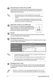
... single VGA card mode, use the PCIe 3.0 x16_1 slot (gray) for a PCI Express x16 graphics card to get better performance. • We recommend that you want to connect a high-definition front panel audio module to this connector is set the Front Panel Type item in the BIOS setup to [HD Audio]. PCI Express 3.0/2.0 x1 slots This motherboard has two PCI Express 3.0/2.0 x1 slots that support PCI Express x1 network cards, SCSI cards, and other cards that comply with the PCI Express specifications. The PCIe x1_1 and PCIe x1_2 slots share bandwidth...
... single VGA card mode, use the PCIe 3.0 x16_1 slot (gray) for a PCI Express x16 graphics card to get better performance. • We recommend that you want to connect a high-definition front panel audio module to this connector is set the Front Panel Type item in the BIOS setup to [HD Audio]. PCI Express 3.0/2.0 x1 slots This motherboard has two PCI Express 3.0/2.0 x1 slots that support PCI Express x1 network cards, SCSI cards, and other cards that comply with the PCI Express specifications. The PCIe x1_1 and PCIe x1_2 slots share bandwidth...

Users Manual English
Page 15
... or keyboard. 2. LAN (RJ-45) port. Refer to the audio configuration table on the next page for the LAN port LED indications. Microphone port (pink). This 15-pin port is for a VGA monitor or other audio sources. 5. This port connects the tape, CD, DVD player, or other VGA-compatible devices. 3. Video Graphics Adapter (VGA) port. This port connects a headphone or a speaker. Chapter 1: Product introduction 1-6 In 4.1-channel, 5.1-channel, and 7.1-channel configurations, the function of the audio ports in 2.1, 4.1, 5.1, or 7.1-channel configuration. Rear panel connectors...
... or keyboard. 2. LAN (RJ-45) port. Refer to the audio configuration table on the next page for the LAN port LED indications. Microphone port (pink). This 15-pin port is for a VGA monitor or other audio sources. 5. This port connects the tape, CD, DVD player, or other VGA-compatible devices. 3. Video Graphics Adapter (VGA) port. This port connects a headphone or a speaker. Chapter 1: Product introduction 1-6 In 4.1-channel, 5.1-channel, and 7.1-channel configurations, the function of the audio ports in 2.1, 4.1, 5.1, or 7.1-channel configuration. Rear panel connectors...
Users Manual English
Page 16
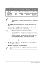
... 7.1-channel configuration Port Light Blue (Rear panel) Lime (Rear panel) Pink (Rear panel) Lime (Front panel) Headset 2.1-channel Line In Line Out Mic In - 4.1-channel 5.1-channel 7.1-channel Rear Speaker Out Rear Speaker Out Rear Speaker Out Front Speaker Out Front Speaker Out Front Speaker Out Mic In Bass/Center Bass/Center - - Side Speaker Out To configure a 7.1-channel audio output: Use a chassis with DVI-I. 1-7 ASUS PRIME B360-PLUS USB 3.1 Gen 1 (up to USB 3.1 Gen 1 devices. 11. These 9-pin Universal Serial Bus (USB) ports connect to 10Gbps) ports (teal blue, Type...
... 7.1-channel configuration Port Light Blue (Rear panel) Lime (Rear panel) Pink (Rear panel) Lime (Front panel) Headset 2.1-channel Line In Line Out Mic In - 4.1-channel 5.1-channel 7.1-channel Rear Speaker Out Rear Speaker Out Rear Speaker Out Front Speaker Out Front Speaker Out Front Speaker Out Mic In Bass/Center Bass/Center - - Side Speaker Out To configure a 7.1-channel audio output: Use a chassis with DVI-I. 1-7 ASUS PRIME B360-PLUS USB 3.1 Gen 1 (up to USB 3.1 Gen 1 devices. 11. These 9-pin Universal Serial Bus (USB) ports connect to 10Gbps) ports (teal blue, Type...
Users Manual English
Page 18
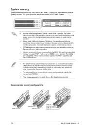
... memory cooling system to support a full memory load (4 DIMMs). • Refer to www.asus.com for the latest Memory QVL (Qualified Vendors List) Recommended memory configurations DIMM_A2* DIMM_B2* DIMM_A2* DIMM_B1 DIMM_B2* DIMM_A1 DIMM_A2* 1-9 ASUS PRIME B360-PLUS Under the default state, some memory modules for overclocking may install varying memory sizes in Channel A and Channel B. Profile is then mapped for the dual-channel configuration. Check with four Double Data Rate 4 (DDR4) Dual Inline Memory Module (DIMM) sockets...
... memory cooling system to support a full memory load (4 DIMMs). • Refer to www.asus.com for the latest Memory QVL (Qualified Vendors List) Recommended memory configurations DIMM_A2* DIMM_B2* DIMM_A2* DIMM_B1 DIMM_B2* DIMM_A1 DIMM_A2* 1-9 ASUS PRIME B360-PLUS Under the default state, some memory modules for overclocking may install varying memory sizes in Channel A and Channel B. Profile is then mapped for the dual-channel configuration. Check with four Double Data Rate 4 (DDR4) Dual Inline Memory Module (DIMM) sockets...
Users Manual English
Page 20
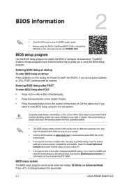
... clear the CMOS and reset the motherboard to view the BIOS update guide. • Before using the BIOS Setup program. BIOS menu screen The BIOS setup program can cause damage to turn the system off then back on how to change between the two modes. 2-1 ASUS PRIME B360-PLUS The BIOS screens include navigation keys and brief online help to enter BIOS Setup using the first two options. Do this motherboard. • If the system becomes unstable after changing any BIOS setting, load the default settings to update...
... clear the CMOS and reset the motherboard to view the BIOS update guide. • Before using the BIOS Setup program. BIOS menu screen The BIOS setup program can cause damage to turn the system off then back on how to change between the two modes. 2-1 ASUS PRIME B360-PLUS The BIOS screens include navigation keys and brief online help to enter BIOS Setup using the first two options. Do this motherboard. • If the system becomes unstable after changing any BIOS setting, load the default settings to update...

Users Manual English
Page 21
... of the selected mode. Chapter 2: BIOS information 2-2 EZ Mode By default, the EZ Mode screen appears when you to the system. Click to switch EZ System Tuning modes Searches by BIOS item name, enter the item name to find the related item listing Enables or disables the Intel Rapid Storage Technology Displays the CPU Fan's speed. Displays the CPU/motherboard temperature, CPU voltage output, CPU/chassis fan speed, and SATA information Selects the display language of the BIOS setup program Displays the system properties...
... of the selected mode. Chapter 2: BIOS information 2-2 EZ Mode By default, the EZ Mode screen appears when you to the system. Click to switch EZ System Tuning modes Searches by BIOS item name, enter the item name to find the related item listing Enables or disables the Intel Rapid Storage Technology Displays the CPU Fan's speed. Displays the CPU/motherboard temperature, CPU voltage output, CPU/chassis fan speed, and SATA information Selects the display language of the BIOS setup program Displays the system properties...
Users Manual English
Page 22
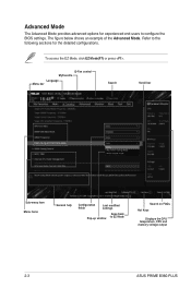
Q-Fan control MyFavorite Language Menu bar Search Scroll bar Sub-menu item Menu items General help Configuration fields Last modified settings Goes back Pop-up window to configure the BIOS settings. To access the EZ Mode, click EZ Mode(F7) or press . Refer to the following sections for experienced end-users to EZ Mode Search on FAQs Hot Keys Displays the CPU temperature, CPU and memory voltage output 2-3 ASUS PRIME B360-PLUS The figure below shows an example of the Advanced Mode. Advanced Mode The Advanced Mode provides advanced options for the detailed configurations.
Q-Fan control MyFavorite Language Menu bar Search Scroll bar Sub-menu item Menu items General help Configuration fields Last modified settings Goes back Pop-up window to configure the BIOS settings. To access the EZ Mode, click EZ Mode(F7) or press . Refer to the following sections for experienced end-users to EZ Mode Search on FAQs Hot Keys Displays the CPU temperature, CPU and memory voltage output 2-3 ASUS PRIME B360-PLUS The figure below shows an example of the Advanced Mode. Advanced Mode The Advanced Mode provides advanced options for the detailed configurations.
Users Manual English
Page 24
...use of shielded cables for a Class B digital device, pursuant to Part 15 of the device. Operation is required to assure compliance with FCC regulations. CAN ICES-3(B)/NMB-3(B) A-1 ASUS PRIME B360-PLUS Compliance Statement of Innovation, Science and Economic Development Canada (ISED) This device complies with the limits for connection of the monitor to the graphics card... uses and can radiate radio frequency energy and, if not installed and used in a residential installation. However, there is no guarantee that to which can be determined by turning the equipment off and on, the user...
...use of shielded cables for a Class B digital device, pursuant to Part 15 of the device. Operation is required to assure compliance with FCC regulations. CAN ICES-3(B)/NMB-3(B) A-1 ASUS PRIME B360-PLUS Compliance Statement of Innovation, Science and Economic Development Canada (ISED) This device complies with the limits for connection of the monitor to the graphics card... uses and can radiate radio frequency energy and, if not installed and used in a residential installation. However, there is no guarantee that to which can be determined by turning the equipment off and on, the user...
Users Manual English
Page 28
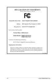
... CONFORMITY Per FCC Part 2 Section 2. 1077(a) Responsible Party Name: Asus Computer International Address: 800 Corporate Way, Fremont, CA 94539. Phone/Fax No: (510)739-3777/(510)608-4555 hereby declares that the product Product Name : Motherboard Model Number :PRIME H370-PLUS, PRIME B360-PLUS Conforms to the following specifications: FCC Part 15, Subpart B, Unintentional Radiators Supplementary Information: This device complies with part 15 of...
... CONFORMITY Per FCC Part 2 Section 2. 1077(a) Responsible Party Name: Asus Computer International Address: 800 Corporate Way, Fremont, CA 94539. Phone/Fax No: (510)739-3777/(510)608-4555 hereby declares that the product Product Name : Motherboard Model Number :PRIME H370-PLUS, PRIME B360-PLUS Conforms to the following specifications: FCC Part 15, Subpart B, Unintentional Radiators Supplementary Information: This device complies with part 15 of...


