User Guide
Page 4
Safeguards Contents Chapter 4: BIOS setup 4.1 Managing and updating your BIOS 4-1 4.1.1 Creating a bootable floppy disk 4-1 4.1.2 Updating the BIOS 4-2 4.1.3 Saving the current BIOS file 4-4 4.2 BIOS Setup program 4-6 4.2.1 BIOS menu screen 4-7 4.2.2 Menu bar 4-7 4.2.3 Navigation keys 4-8 4.2.4 General help 4-8 4.2.5 Sub-menu 4-8 4.2.6 Scroll bar 4-8 4.2.7 Pop-up window 4-8 4.3 Main menu 4-9 4.3.1...34 4.6.3 Removable Device Priority 4-34 4.6.4 Boot Settings Configuration 4-35 4.6.5 Security 4-37 4.7 Exit menu 4-38 Appendix: Reference information A.1 PCH-DR block diagram A-1 iv
Safeguards Contents Chapter 4: BIOS setup 4.1 Managing and updating your BIOS 4-1 4.1.1 Creating a bootable floppy disk 4-1 4.1.2 Updating the BIOS 4-2 4.1.3 Saving the current BIOS file 4-4 4.2 BIOS Setup program 4-6 4.2.1 BIOS menu screen 4-7 4.2.2 Menu bar 4-7 4.2.3 Navigation keys 4-8 4.2.4 General help 4-8 4.2.5 Sub-menu 4-8 4.2.6 Scroll bar 4-8 4.2.7 Pop-up window 4-8 4.3 Main menu 4-9 4.3.1...34 4.6.3 Removable Device Priority 4-34 4.6.4 Boot Settings Configuration 4-35 4.6.5 Security 4-37 4.7 Exit menu 4-38 Appendix: Reference information A.1 PCH-DR block diagram A-1 iv
User Guide
Page 7
... refer to change system settings through the BIOS Setup menus. About this guide is organized This manual contains the following parts: • Chapter 1: Product introduction This chapter describes the features of the PCH-DR motherboard. How this guide This user guide contains... the information you have to perform when installing system components. vii It includes description of the BIOS parameters are also provided. • Appendix: Reference information ...
... refer to change system settings through the BIOS Setup menus. About this guide is organized This manual contains the following parts: • Chapter 1: Product introduction This chapter describes the features of the PCH-DR motherboard. How this guide This user guide contains... the information you have to perform when installing system components. vii It includes description of the BIOS parameters are also provided. • Appendix: Reference information ...
User Guide
Page 10
PCH-DR specifications summary BIOS features 4Mb Flash ROM, Phoenix-Award BIOS, PnP, DMI2.0, WfM2.0, SM BIOS2.3 Industry standard PCI 2.2, PCI-X 1.0a, USB 2.0 Manageability WfM 2.0. DMI 2.0, WOL/WOR by PME, chassis intrusion Power requirement SSI-type power supply (with 24-pin and 8-pin power plugs) Form Factor Extended ATX form factor: 12in x 10.5in (30.5cm x 26.7cm) Support CD contents Device drivers Management software System utilities ASUS contact information *Specifications are subject to change without notice. x
PCH-DR specifications summary BIOS features 4Mb Flash ROM, Phoenix-Award BIOS, PnP, DMI2.0, WfM2.0, SM BIOS2.3 Industry standard PCI 2.2, PCI-X 1.0a, USB 2.0 Manageability WfM 2.0. DMI 2.0, WOL/WOR by PME, chassis intrusion Power requirement SSI-type power supply (with 24-pin and 8-pin power plugs) Form Factor Extended ATX form factor: 12in x 10.5in (30.5cm x 26.7cm) Support CD contents Device drivers Management software System utilities ASUS contact information *Specifications are subject to change without notice. x

User Guide
Page 21
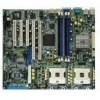
mPGA 604 30.5cm (12in) 2.2.3 Motherboard layout mPGA 604 COM1 PS/2KBMS T: Mouse B: Keyboard USB12 PSUSMB1 KBPWR1 USBPW12 REAR_FAN1 REAR_FAN2 26.8cm (10.5in) ATXPWR1 ATX12V1 Intel E7210 MCH ...XL VGA Controller PCI2 (32-bit, 33MHz 5V) PCI3 (32-bit, 33MHz 5V) BMCCONN1 SB_PWR1 COM2 BPSMB1 LPT1 Super I/O CLRTC1 PCH-DR USBPW34 USB34 FLOPPY1 4Mbit Flash BIOS PANEL1 SEC_IDE1 SATA1 SATA_RAID2 SATA2 RECOVERY1 FRNT_FAN1 FRNT_FAN2 DSW1 RAID_EN1 SATA_RAID1 PROMISE PDC20378 RAID Controller AUX_PANEL1 CR2032 3V Lithium Cell CMOS Power PRI_RAID1 BUZZER1 ASUS PCH-DR motherboard 2-3
mPGA 604 30.5cm (12in) 2.2.3 Motherboard layout mPGA 604 COM1 PS/2KBMS T: Mouse B: Keyboard USB12 PSUSMB1 KBPWR1 USBPW12 REAR_FAN1 REAR_FAN2 26.8cm (10.5in) ATXPWR1 ATX12V1 Intel E7210 MCH ...XL VGA Controller PCI2 (32-bit, 33MHz 5V) PCI3 (32-bit, 33MHz 5V) BMCCONN1 SB_PWR1 COM2 BPSMB1 LPT1 Super I/O CLRTC1 PCH-DR USBPW34 USB34 FLOPPY1 4Mbit Flash BIOS PANEL1 SEC_IDE1 SATA1 SATA_RAID2 SATA2 RECOVERY1 FRNT_FAN1 FRNT_FAN2 DSW1 RAID_EN1 SATA_RAID1 PROMISE PDC20378 RAID Controller AUX_PANEL1 CR2032 3V Lithium Cell CMOS Power PRI_RAID1 BUZZER1 ASUS PCH-DR motherboard 2-3
User Guide
Page 34
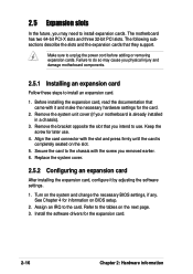
...See Chapter 4 for the card. 2. Failure to do so may need to the tables on BIOS setup. 2. 2.5 Expansion slots In the future, you may cause you physical injury and damage motherboard components. 2.5.1 Installing an expansion card Follow these steps to the card. Remove the system unit cover... (if your motherboard is completely seated on the system and change the necessary BIOS settings, if any. Refer to install ...
...See Chapter 4 for the card. 2. Failure to do so may need to the tables on BIOS setup. 2. 2.5 Expansion slots In the future, you may cause you physical injury and damage motherboard components. 2.5.1 Installing an expansion card Follow these steps to the card. Remove the system unit cover... (if your motherboard is completely seated on the system and change the necessary BIOS settings, if any. Refer to install ...
User Guide
Page 37
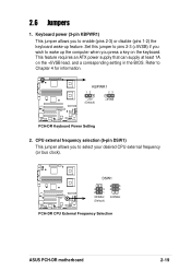
... requires an ATX power supply that can supply at least 1A on the keyboard. DSW1 4 3 2 1 533MHz (Default) 6 5 4 3 400MHz PCH-DR PCH-DR CPU External Frequency Selection ASUS PCH-DR motherboard 2-19 2.6 Jumpers 1. Refer to enable (pins 2-3) or disable (pins 1-2) the keyboard wake-up the computer when you press a key on the +5VSB lead, and a corresponding setting in the BIOS. KBPWR1...
... requires an ATX power supply that can supply at least 1A on the keyboard. DSW1 4 3 2 1 533MHz (Default) 6 5 4 3 400MHz PCH-DR PCH-DR CPU External Frequency Selection ASUS PCH-DR motherboard 2-19 2.6 Jumpers 1. Refer to enable (pins 2-3) or disable (pins 1-2) the keyboard wake-up the computer when you press a key on the +5VSB lead, and a corresponding setting in the BIOS. KBPWR1...

User Guide
Page 40
Prepare a floppy disk that contains the latest BIOS for the motherboard (xxxx-xxx.BIN) and the AWDFLASH.EXE utility. 2. Onboard VGA setting (3-pin VGA_EN1) This jumper allows you to enable or disable the onboard VGA. To update the BIOS: 1. Shut down the system. 5. Set ...you wish to pins 1-2. 6. Insert the floppy disk then turn on the system. RECOVERY1 12 23 Normal (Default) PCH-DR PCH-DR BIOS Recovery Setting BIOS Recovery 8. Set the jumper to update the BIOS. 4. PCH-DR PCH-DR VGA Setting VGA_EN1 12 23 Enable (Default) Disable 2-22 Chapter 2: Hardware information 7.
Prepare a floppy disk that contains the latest BIOS for the motherboard (xxxx-xxx.BIN) and the AWDFLASH.EXE utility. 2. Onboard VGA setting (3-pin VGA_EN1) This jumper allows you to enable or disable the onboard VGA. To update the BIOS: 1. Shut down the system. 5. Set ...you wish to pins 1-2. 6. Insert the floppy disk then turn on the system. RECOVERY1 12 23 Normal (Default) PCH-DR PCH-DR BIOS Recovery Setting BIOS Recovery 8. Set the jumper to update the BIOS. 4. PCH-DR PCH-DR VGA Setting VGA_EN1 12 23 Enable (Default) Disable 2-22 Chapter 2: Hardware information 7.
User Guide
Page 41
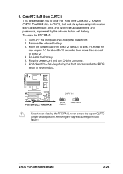
... system boot failure! To erase the RTC RAM: 1. Move the jumper cap from pins 1-2 (default) to re-enter data. ASUS PCH-DR motherboard 2-23 Clear RTC RAM (3-pin CLRTC1) This jumper allows you to pins 1-2. 4. Plug the power cord and turn ON the ...computer. 6. Re-install the battery. 5. PCH-DR PCH-DR Clear RTC RAM CLRTC1 12 23 Normal (Default) Clear CMOS Except when clearing the RTC RAM, never remove the cap on...RAM data in CMOS. Hold down the key during the boot process and enter BIOS setup to pins 2-3.
... system boot failure! To erase the RTC RAM: 1. Move the jumper cap from pins 1-2 (default) to re-enter data. ASUS PCH-DR motherboard 2-23 Clear RTC RAM (3-pin CLRTC1) This jumper allows you to pins 1-2. 4. Plug the power cord and turn ON the ...computer. 6. Re-install the battery. 5. PCH-DR PCH-DR Clear RTC RAM CLRTC1 12 23 Normal (Default) Clear CMOS Except when clearing the RTC RAM, never remove the cap on...RAM data in CMOS. Hold down the key during the boot process and enter BIOS setup to pins 2-3.
User Guide
Page 46
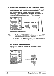
...connector (124-pin BMCCONN1) This connector is for better performance. 7. Configure the onboard device and SATA items in BIOS to page 4-17 fro information. Serial ATA RAID connectors (7-pin SATA_RAID1, SATA_RAID2) These Serial ATA connectors support SATA ...to use both Parallel ATA and Serial ATA devices for ASUS PCI-X server management card, if available. +5VSB +5VSB BMC SMBCLK 12CCLK1 PSON# BMC_RST# PWROK PSONEN# +5VSB +5VSB BMC SMBDATA 12CDATA1 FP_PWRBTN# BMC_PRESENT# BMC_SMI# GND BMCCONN1 PCH-DR PCH-DR BMC Connector 2-28 Chapter 2: Hardware information SATA_RAID1 SATA_RAID2 ...
...connector (124-pin BMCCONN1) This connector is for better performance. 7. Configure the onboard device and SATA items in BIOS to page 4-17 fro information. Serial ATA RAID connectors (7-pin SATA_RAID1, SATA_RAID2) These Serial ATA connectors support SATA ...to use both Parallel ATA and Serial ATA devices for ASUS PCI-X server management card, if available. +5VSB +5VSB BMC SMBCLK 12CCLK1 PSON# BMC_RST# PWROK PSONEN# +5VSB +5VSB BMC SMBDATA 12CDATA1 FP_PWRBTN# BMC_PRESENT# BMC_SMI# GND BMCCONN1 PCH-DR PCH-DR BMC Connector 2-28 Chapter 2: Hardware information SATA_RAID1 SATA_RAID2 ...

User Guide
Page 50
...+ MLEDNC +5V GND GND SPKROUT HDLED+ HDLEDNMIBTN# GND POWERBTN# GND NC RESETBTN# GND PANEL1 PCH-DR PCH-DR System Panel Connector • System Power LED (3-pin PLED) This lead connects to the case-mounted speaker and allows you turn on the BIOS or OS settings. The LED lights up . • Power switch / Soft-off switch...
...+ MLEDNC +5V GND GND SPKROUT HDLED+ HDLEDNMIBTN# GND POWERBTN# GND NC RESETBTN# GND PANEL1 PCH-DR PCH-DR System Panel Connector • System Power LED (3-pin PLED) This lead connects to the case-mounted speaker and allows you turn on the BIOS or OS settings. The LED lights up . • Power switch / Soft-off switch...

User Guide
Page 53
Chapter 3 This chapter describes the power up Powering up sequence and gives information on the BIOS beep codes.
Chapter 3 This chapter describes the power up Powering up sequence and gives information on the BIOS beep codes.
User Guide
Page 55
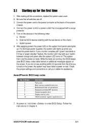
...4. If your retailer for the first time 1. The system then runs the power-on the screen. While the tests are off. 3. ASUS PCH-DR motherboard 3-1 Check the jumper settings and connections or call your monitor complies with "green" standards or if it has a "power standby" feature...all the connections, replace the system case cover. 2. Monitor b. If you do not see BIOS beep codes table below) or additional messages appear on tests. Connect the power cord to enter BIOS Setup. External SCSI devices (starting with a surge protector. 5. Follow the instructions in the ...
...4. If your retailer for the first time 1. The system then runs the power-on the screen. While the tests are off. 3. ASUS PCH-DR motherboard 3-1 Check the jumper settings and connections or call your monitor complies with "green" standards or if it has a "power standby" feature...all the connections, replace the system case cover. 2. Monitor b. If you do not see BIOS beep codes table below) or additional messages appear on tests. Connect the power cord to enter BIOS Setup. External SCSI devices (starting with a surge protector. 5. Follow the instructions in the ...

User Guide
Page 56
... button is ON, pressing the power switch for more than 4 seconds puts the system to sleep mode or to soft-off mode regardless of the BIOS setting. Click the Turn Off button to shut down the computer. 3. Pressing the power switch for less than 4 seconds lets the system enter the... soft-off mode, depending on the BIOS setting. If you are using Windows® 2000 Professional or Windows® 2000 Server: 1. The power supply should turn off after Windows® shuts ...
... button is ON, pressing the power switch for more than 4 seconds puts the system to sleep mode or to soft-off mode regardless of the BIOS setting. Click the Turn Off button to shut down the computer. 3. Pressing the power switch for less than 4 seconds lets the system enter the... soft-off mode, depending on the BIOS setting. If you are using Windows® 2000 Professional or Windows® 2000 Server: 1. The power supply should turn off after Windows® shuts ...
User Guide
Page 57
BIOS setup Chapter 4 This chapter tells how to change system settings through the BIOS Setup menus. Detailed descriptions of the BIOS parameters are also provided.
BIOS setup Chapter 4 This chapter tells how to change system settings through the BIOS Setup menus. Detailed descriptions of the BIOS parameters are also provided.

User Guide
Page 58
Chapter summary 4.1 Managing and updating your BIOS 4-1 4.2 BIOS Setup program 4-6 4.3 Main menu 4-9 4.4 Advanced menu 4-15 4.5 Power menu 4-28 4.6 Boot menu 4-33 4.7 Exit menu 4-38 ASUS PCH-DR motherboard
Chapter summary 4.1 Managing and updating your BIOS 4-1 4.2 BIOS Setup program 4-6 4.3 Main menu 4-9 4.4 Advanced menu 4-15 4.5 Power menu 4-28 4.6 Boot menu 4-33 4.7 Exit menu 4-38 ASUS PCH-DR motherboard
User Guide
Page 59
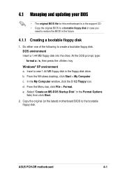
...-DOS Startup Disk" in the floppy disk drive. b. d. e. ASUS PCH-DR motherboard 4-1 At the DOS prompt, type: format a: /s, then press the key Windows® XP environment a. c. 4.1 Managing and updating your BIOS • The original BIOS file for this motherboard is in the support CD. • Copy the original BIOS to a bootable floppy disk in case you need to...
...-DOS Startup Disk" in the floppy disk drive. b. d. e. ASUS PCH-DR motherboard 4-1 At the DOS prompt, type: format a: /s, then press the key Windows® XP environment a. c. 4.1 Managing and updating your BIOS • The original BIOS file for this motherboard is in the support CD. • Copy the original BIOS to a bootable floppy disk in case you need to...
User Guide
Page 60
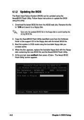
...using the bootable floppy disk you created earlier. 4. Copy the AwardBIOS Flash Utility (awdflash.exe) from the ASUS web site. When the A:> appears, replace the bootable floppy disk with the latest BIOS file. 3. PSCHSR-IDE DATE: 05/16/2004 Flash Type - At the prompt, type awdflash then press... . AwardBIOS Flash Utility for ASUS V1.01 (C) Phoenix Technologies Ltd. Rename the file to *.BIN and save it to...
...using the bootable floppy disk you created earlier. 4. Copy the AwardBIOS Flash Utility (awdflash.exe) from the ASUS web site. When the A:> appears, replace the bootable floppy disk with the latest BIOS file. 3. PSCHSR-IDE DATE: 05/16/2004 Flash Type - At the prompt, type awdflash then press... . AwardBIOS Flash Utility for ASUS V1.01 (C) Phoenix Technologies Ltd. Rename the file to *.BIN and save it to...

User Guide
Page 61
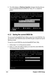
... you to Program field, then press . SST 49LF004A/B /3.3V File Name to save the current BIOS file to the floppy disk, or to Program : 1001.bin Message: Do You Want To Save BIOS (Y/N) 7. Press to save the file. ASUS PCH-DR motherboard 4-3 6. All Rights Reserved For Canterwood - AwardBIOS Flash Utility for details on saving the current...
... you to Program field, then press . SST 49LF004A/B /3.3V File Name to save the current BIOS file to the floppy disk, or to Program : 1001.bin Message: Do You Want To Save BIOS (Y/N) 7. Press to save the file. ASUS PCH-DR motherboard 4-3 6. All Rights Reserved For Canterwood - AwardBIOS Flash Utility for details on saving the current...
User Guide
Page 62
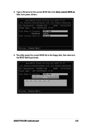
...can use the AwardBIOS Flash Utility to Program : 1001.bin Save current BIOS as : Message: 4-4 Chapter 4: BIOS Setup Press when the utility prompts you have successfully flashed the BIOS file. AwardBIOS Flash Utility for ASUS V1.01 (C) Phoenix Technologies Ltd. Press to 6 of the previous ...section. 2. The following screen appears. All Rights Reserved For Canterwood - To save the current BIOS file. PSCHSR-IDE DATE: 05/16/2004 Flash Type - AwardBIOS Flash Utility for ASUS V1.01 (C) Phoenix Technologies Ltd. SST 49LF004A/B /3.3V File Name to save the current...
...can use the AwardBIOS Flash Utility to Program : 1001.bin Save current BIOS as : Message: 4-4 Chapter 4: BIOS Setup Press when the utility prompts you have successfully flashed the BIOS file. AwardBIOS Flash Utility for ASUS V1.01 (C) Phoenix Technologies Ltd. Press to 6 of the previous ...section. 2. The following screen appears. All Rights Reserved For Canterwood - To save the current BIOS file. PSCHSR-IDE DATE: 05/16/2004 Flash Type - AwardBIOS Flash Utility for ASUS V1.01 (C) Phoenix Technologies Ltd. SST 49LF004A/B /3.3V File Name to save the current...
User Guide
Page 63
... to Program : 1001.bin Now Backup System BIOS to the BIOS flashing process. The utility saves the current BIOS file to the floppy disk, then returns to File! 11112222333344445555666677778888999900001111222233334444555566667777888899990000111122223333444455556666777788889999000011112222111122223333444455556666777788889999000011112222 Message: Please Wait!Reset ASUS PCH-DR motherboard 4-5 AwardBIOS Flash Utility for ASUS V1.01 (C) Phoenix Technologies Ltd. AwardBIOS Flash Utility for ASUS V1.01 (C) Phoenix Technologies Ltd. All Rights...
... to Program : 1001.bin Now Backup System BIOS to the BIOS flashing process. The utility saves the current BIOS file to the floppy disk, then returns to File! 11112222333344445555666677778888999900001111222233334444555566667777888899990000111122223333444455556666777788889999000011112222111122223333444455556666777788889999000011112222 Message: Please Wait!Reset ASUS PCH-DR motherboard 4-5 AwardBIOS Flash Utility for ASUS V1.01 (C) Phoenix Technologies Ltd. AwardBIOS Flash Utility for ASUS V1.01 (C) Phoenix Technologies Ltd. All Rights...


