
User Guide
Page 1
P9D-V Motherboard
P9D-V Motherboard

User Guide
Page 3
......viii Electrical safety viii Operation safety viii Australia statement notice ix P9D-V Specifications Summary xi Chapter 1: Product Introduction 1.1 Welcome!...1-3 1.2 Package contents 1-3 1.3 Serial number label 1-4 1.4 Special features 1-4 1.4.1 Product highlights 1-4 1.4.2 Innovative ASUS features 1-6 Chapter 2: Hardware Information 2.1 Before you proceed 2-3 2.2 Motherboard overview 2-4 2.2.1 Placement direction 2-4 2.2.2 Screw holes 2-4 2.2.3 Motherboard layout 2-5 2.2.4 Layout contents 2-6 2.3 Central Processing Unit (CPU 2-8 2.3.1 Installing the CPU...
......viii Electrical safety viii Operation safety viii Australia statement notice ix P9D-V Specifications Summary xi Chapter 1: Product Introduction 1.1 Welcome!...1-3 1.2 Package contents 1-3 1.3 Serial number label 1-4 1.4 Special features 1-4 1.4.1 Product highlights 1-4 1.4.2 Innovative ASUS features 1-6 Chapter 2: Hardware Information 2.1 Before you proceed 2-3 2.2 Motherboard overview 2-4 2.2.1 Placement direction 2-4 2.2.2 Screw holes 2-4 2.2.3 Motherboard layout 2-5 2.2.4 Layout contents 2-6 2.3 Central Processing Unit (CPU 2-8 2.3.1 Installing the CPU...

User Guide
Page 8
... problems with the package. • Before using the product, make sure all power cables are not damaged. Operation safety • Before installing the motherboard and adding devices on a stable surface. • If you add a device. • Before connecting or removing signal cables from the.... If you are not sure about the voltage of the electrical outlet you detect any area where it by yourself. DO NOT throw the motherboard in municipal waste. If you are connected. This product has been designed to enable proper reuse of the crossed out wheeled bin indicates that ...
... problems with the package. • Before using the product, make sure all power cables are not damaged. Operation safety • Before installing the motherboard and adding devices on a stable surface. • If you add a device. • Before connecting or removing signal cables from the.... If you are not sure about the voltage of the electrical outlet you detect any area where it by yourself. DO NOT throw the motherboard in municipal waste. If you are connected. This product has been designed to enable proper reuse of the crossed out wheeled bin indicates that ...

User Guide
Page 14
This chapter contains the following sections: 1.1 Welcome!...1-3 1.2 Package contents 1-3 1.3 Serial number label 1-4 1.4 Special features 1-4 ASUS Chapter summary 1 This chapter describes the motherboard features and the new technologies it supports.
This chapter contains the following sections: 1.1 Welcome!...1-3 1.2 Package contents 1-3 1.3 Serial number label 1-4 1.4 Special features 1-4 ASUS Chapter summary 1 This chapter describes the motherboard features and the new technologies it supports.

User Guide
Page 15
... Pack I/O Shield SATA DOM Power cable Cables SATA 3G cable SATA 6G cable Application CD Support CD ASWM Enterprise SDVD Documentation Motherboard User Guide Accessory Metal Plate for buying an ASUS® P9D-V motherboard! ASUS 1-3 1.1 Welcome! Before you for LGA1150 Packaging Qty. 1 1 2 4 1 1 1 1 1 pc per carton Standard Bulk Pack 1 ---1 1 1 1 10 pcs per carton If any of...
... Pack I/O Shield SATA DOM Power cable Cables SATA 3G cable SATA 6G cable Application CD Support CD ASWM Enterprise SDVD Documentation Motherboard User Guide Accessory Metal Plate for buying an ASUS® P9D-V motherboard! ASUS 1-3 1.1 Welcome! Before you for LGA1150 Packaging Qty. 1 1 2 4 1 1 1 1 1 pc per carton Standard Bulk Pack 1 ---1 1 1 1 10 pcs per carton If any of...

User Guide
Page 16
...motherboard's serial number containing 12 characters xxS2xxxxxxxx shown as the figure below its power, current, and temperature specification limits. Intel® Hyper Threading The thread-level parallelism on today's multithreaded software. 1.3 Serial number label Before requesting support from the ASUS...is operating below . The Intel® EM64T feature allows your problems. P9D-V xxS2xxxxxxxx Made in China 合格 1.4 Special features 1.4.1 Product highlights Latest processor technology This motherboard supports the latest Intel® Xeon® Processor E3-1200 v3/ ...
...motherboard's serial number containing 12 characters xxS2xxxxxxxx shown as the figure below its power, current, and temperature specification limits. Intel® Hyper Threading The thread-level parallelism on today's multithreaded software. 1.3 Serial number label Before requesting support from the ASUS...is operating below . The Intel® EM64T feature allows your problems. P9D-V xxS2xxxxxxxx Made in China 合格 1.4 Special features 1.4.1 Product highlights Latest processor technology This motherboard supports the latest Intel® Xeon® Processor E3-1200 v3/ ...

User Guide
Page 17
... for critical components. PCI Express 3.0 PCI Express 3.0 (PCIe 3.0) is backward compatible with USB 1.1. Serial ATA III technology The motherboard supports the Serial ATA III 6 Gb/s technology through the Serial ATA interface and Intel® C224 chipset. Get enhanced scalability, ... compatibility to 6Gbps data transfer rates. USB 2.0 technology The motherboard implements the Universal Serial Bus (USB) 2.0 specification that provides twice the performance and speed of up to PCIe 1.0/2.0 devices. ASUS 1-5 It provides an optimal graphics performance, unprecedented data speed,...
... for critical components. PCI Express 3.0 PCI Express 3.0 (PCIe 3.0) is backward compatible with USB 1.1. Serial ATA III technology The motherboard supports the Serial ATA III 6 Gb/s technology through the Serial ATA interface and Intel® C224 chipset. Get enhanced scalability, ... compatibility to 6Gbps data transfer rates. USB 2.0 technology The motherboard implements the Universal Serial Bus (USB) 2.0 specification that provides twice the performance and speed of up to PCIe 1.0/2.0 devices. ASUS 1-5 It provides an optimal graphics performance, unprecedented data speed,...

User Guide
Page 20
It includes description of the jumpers and connectors on the motherboard. This chapter contains the following sections: 2.1 Before you have to perform when installing system components. Chapter summary 2 This chapter lists the hardware setup procedures that you proceed 2-3 2.2 Motherboard overview 2-4 2.3 Central Processing Unit (CPU 2-8 2.4 System memory 2-14 2.5 Expansion slots 2-16 2.6 Onboard LEDs 2-21 2.7 Jumpers...2-24 2.8 Connectors 2-29 Chapter 1: Product introduction
It includes description of the jumpers and connectors on the motherboard. This chapter contains the following sections: 2.1 Before you have to perform when installing system components. Chapter summary 2 This chapter lists the hardware setup procedures that you proceed 2-3 2.2 Motherboard overview 2-4 2.3 Central Processing Unit (CPU 2-8 2.4 System memory 2-14 2.5 Expansion slots 2-16 2.6 Onboard LEDs 2-21 2.7 Jumpers...2-24 2.8 Connectors 2-29 Chapter 1: Product introduction

User Guide
Page 21
2.1 Before you proceed Take note of the following precautions before you install motherboard components or change any motherboard settings. • Unplug the power cord from the wall socket before touching any component. • Use a ...supply case, before handling components to avoid damaging them due to static electricity. • Hold components by the edges to the motherboard, peripherals, and/or components. Failure to do so may cause severe damage to avoid touching the ICs on them. •...the power supply is switched off or the power cord is detached from the power supply. ASUS 2-3
2.1 Before you proceed Take note of the following precautions before you install motherboard components or change any motherboard settings. • Unplug the power cord from the wall socket before touching any component. • Use a ...supply case, before handling components to avoid damaging them due to static electricity. • Hold components by the edges to the motherboard, peripherals, and/or components. Failure to do so may cause severe damage to avoid touching the ICs on them. •...the power supply is switched off or the power cord is detached from the power supply. ASUS 2-3

User Guide
Page 22
...2: Hardware information Doing so can cause you physical injury and damage motherboard components! 2.2.1 Placement direction When installing the motherboard, ensure that you install it in the correct orientation. To optimize the motherboard features, we highly recommend that you place it . The edge with...the chassis in an ATX 1.1 compliant chassis. Failure to do so can damage the motherboard. 2.2 Motherboard overview Before you install the motherboard, study the configuration of your chassis to ensure that the motherboard fits into it into the holes indicated by circles to secure the...
...2: Hardware information Doing so can cause you physical injury and damage motherboard components! 2.2.1 Placement direction When installing the motherboard, ensure that you install it in the correct orientation. To optimize the motherboard features, we highly recommend that you place it . The edge with...the chassis in an ATX 1.1 compliant chassis. Failure to do so can damage the motherboard. 2.2 Motherboard overview Before you install the motherboard, study the configuration of your chassis to ensure that the motherboard fits into it into the holes indicated by circles to secure the...

User Guide
Page 23
2.2.3 Motherboard layout ASUS 2-5
2.2.3 Motherboard layout ASUS 2-5

User Guide
Page 26
... incorrect CPU installation/removal, or misplacement/loss/incorrect removal of the PnP cap. 2.3.1 Installing the CPU To install the CPU: 1. ASUS will shoulder the cost of repair only if the damage is on the socket and the socket contacts are not bent. Before installing .... • The product warranty does not cover damage to the PnP cap/socket contacts/motherboard components. Locate the CPU socket on your right. 2-8 Chapter 2: Hardware information 2.3 Central Processing Unit (CPU) The motherboard comes with a surface mount LGA1150 socket designed for the Intel® Xeon® E3...
... incorrect CPU installation/removal, or misplacement/loss/incorrect removal of the PnP cap. 2.3.1 Installing the CPU To install the CPU: 1. ASUS will shoulder the cost of repair only if the damage is on the socket and the socket contacts are not bent. Before installing .... • The product warranty does not cover damage to the PnP cap/socket contacts/motherboard components. Locate the CPU socket on your right. 2-8 Chapter 2: Hardware information 2.3 Central Processing Unit (CPU) The motherboard comes with a surface mount LGA1150 socket designed for the Intel® Xeon® E3...

User Guide
Page 29
... fan: 1. Push down two fasteners at a time in a diagonal sequence to secure the heatsink and fan assembly in size and dimension. ASUS 2-11 Ensure that you have installed the motherboard to the chassis before you install the heatsink and fan assembly. The LGA1150 socket is closest to the CPU fan connector. 2.3.2 Installing... and CPU fan assembly only. If you purchased a separate CPU heatsink and fan assembly, ensure that the Thermal Interface Material is included depending on the motherboard. 2.
... fan: 1. Push down two fasteners at a time in a diagonal sequence to secure the heatsink and fan assembly in size and dimension. ASUS 2-11 Ensure that you have installed the motherboard to the chassis before you install the heatsink and fan assembly. The LGA1150 socket is closest to the CPU fan connector. 2.3.2 Installing... and CPU fan assembly only. If you purchased a separate CPU heatsink and fan assembly, ensure that the Thermal Interface Material is included depending on the motherboard. 2.

User Guide
Page 30
... CPU_FAN1. 3. Connect the CPU fan cable to disengage the heatsink and fan assembly from the motherboard. 2-12 Chapter 2: Hardware information B 3. Rotate each fastener counterclockwise. A B A A B B A 4. DO NOT forget to plug this connector. 2.3.3 Uninstalling the CPU ... fan To uninstall the CPU heatsink and fan: 1. Carefully remove the heatsink and fan assembly from the motherboard. Pull up two fasteners at a time in a diagonal sequence to the connector on the motherboard. 2. Hardware monitoring errors can occur if you fail to connect the CPU fan connector!
... CPU_FAN1. 3. Connect the CPU fan cable to disengage the heatsink and fan assembly from the motherboard. 2-12 Chapter 2: Hardware information B 3. Rotate each fastener counterclockwise. A B A A B B A 4. DO NOT forget to plug this connector. 2.3.3 Uninstalling the CPU ... fan To uninstall the CPU heatsink and fan: 1. Carefully remove the heatsink and fan assembly from the motherboard. Pull up two fasteners at a time in a diagonal sequence to the connector on the motherboard. 2. Hardware monitoring errors can occur if you fail to connect the CPU fan connector!

User Guide
Page 31
ASUS 2-13 Doing so can damage the CPU. Do not overtighten the screws. A C D B A C D B 1. Ensure that you use qualified heatsink assembly only. • Ensure that the heatsink ... have applied the thermal interface material to tighten the four heatsink screws using the recommended sequence below. Use a Phillips screwdriver to the top of the motherboard, matching the standoffs to the heatsink screw holes. 2. Peel off the sticker on the heatsink metal plate and affix the plate to the back of...
ASUS 2-13 Doing so can damage the CPU. Do not overtighten the screws. A C D B A C D B 1. Ensure that you use qualified heatsink assembly only. • Ensure that the heatsink ... have applied the thermal interface material to tighten the four heatsink screws using the recommended sequence below. Use a Phillips screwdriver to the top of the motherboard, matching the standoffs to the heatsink screw holes. 2. Peel off the sticker on the heatsink metal plate and affix the plate to the back of...

User Guide
Page 32
2.4 System memory 2.4.1 Overview The motherboard comes with less power consumption. A DDR3 module has the same physical dimensions as a DDR2 DIMM but is recommended that you obtain memory modules from the ...
2.4 System memory 2.4.1 Overview The motherboard comes with less power consumption. A DDR3 module has the same physical dimensions as a DDR2 DIMM but is recommended that you obtain memory modules from the ...

User Guide
Page 33
... a socket in any further to the user guide for qualified vendor lists of the DIMM. The DIMM might get damaged when it fits in the motherboard package. • Refer to ensure proper sitting of the memory modules. Locked Retaining Clip Always insert the DIMM into place and the DIMM cannot be...
... a socket in any further to the user guide for qualified vendor lists of the DIMM. The DIMM might get damaged when it fits in the motherboard package. • Refer to ensure proper sitting of the memory modules. Locked Retaining Clip Always insert the DIMM into place and the DIMM cannot be...
User Guide
Page 34
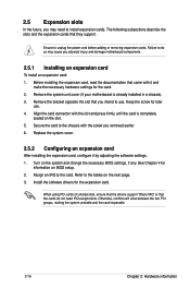
...removed earlier. 6. Turn on the slot. 5. See Chapter 4 for the expansion card. 2.5 Expansion slots In the future, you physical injury and damage motherboard components. 2.5.1 Installing an expansion card To install an expansion card: 1. Ensure to the card. Failure to do not need to use . 4. Keep the... drivers for information on BIOS setup. 2. When using PCI cards on the next page. 3. Remove the system unit cover (if your motherboard is completely seated on the system and change the necessary BIOS settings, if any. Align the card connector with the screw you intend to...
...removed earlier. 6. Turn on the slot. 5. See Chapter 4 for the expansion card. 2.5 Expansion slots In the future, you physical injury and damage motherboard components. 2.5.1 Installing an expansion card To install an expansion card: 1. Ensure to the card. Failure to do not need to use . 4. Keep the... drivers for information on BIOS setup. 2. When using PCI cards on the next page. 3. Remove the system unit cover (if your motherboard is completely seated on the system and change the necessary BIOS settings, if any. Align the card connector with the screw you intend to...

User Guide
Page 37
...the MIO card slot. 2. 2.5.7 Installing the Audio card 1. Ensure that it is 3 completely seated on the motherboard. 2. ASUS 2-19 Insert the audio card into the MIO slot on the motherboard and align the golden fingers of the Thermal Sensor cable to the device you would like to the connector. 3.... Secure the audio card to the connector on your motherboard. 1. Connect the Thermal Sensor cable to monitor temperature....
...the MIO card slot. 2. 2.5.7 Installing the Audio card 1. Ensure that it is 3 completely seated on the motherboard. 2. ASUS 2-19 Insert the audio card into the MIO slot on the motherboard and align the golden fingers of the Thermal Sensor cable to the device you would like to the connector. 3.... Secure the audio card to the connector on your motherboard. 1. Connect the Thermal Sensor cable to monitor temperature....

User Guide
Page 38
The illustration below shows the location of the onboard LED. 2. 2.6 Onboard LEDs 1. This is on button is pressed and the system is a reminder that the system is ON, in sleep mode, or in any motherboard component. Standby Power LED (SB_PWR1) The motherboard comes with a standby power LED. Power LED (+5V_LED1) This LED lights up to indicate that you should shut down the system and unplug the power cable before removing or plugging in soft-off mode. The green LED lights up when the Power-on . 2-20 Chapter 2: Hardware information
The illustration below shows the location of the onboard LED. 2. 2.6 Onboard LEDs 1. This is on button is pressed and the system is a reminder that the system is ON, in sleep mode, or in any motherboard component. Standby Power LED (SB_PWR1) The motherboard comes with a standby power LED. Power LED (+5V_LED1) This LED lights up to indicate that you should shut down the system and unplug the power cable before removing or plugging in soft-off mode. The green LED lights up when the Power-on . 2-20 Chapter 2: Hardware information

