User Manual
Page 23
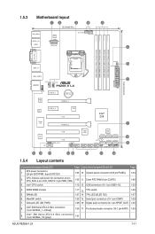
...ELED 730) 1-37 6. Intel® Z68 Serial ATA 6.0 Gb/s connectors (7-pin SATA6G_1/2 [gray]) 1-31 ASUS P8Z68-V LX 1-11 Intel® CPU socket 4. Serial port connectors (10-1 pin COM1) 1-29 7. 1.5.3 Motherboard layout...CMOS Power ASM 1042 PCIEX16_1 RTL 8111E Super I/O PCIEX1_2 TPU PCI1 PCIEX16_2 Intel® Z68 7 PCI2 ASM 1083 64Mb BIOS SATA3G_2 SATA3G_3 SATA3G_4 ALC 887 8 PCI3 SB_PWR SATA6G_2 SATA6G_1 SPDIF_OUT ELED730 SATA3G_1 9 CLRTC COM1 TPU USB1112 USB910 USB78 USB56 PANEL 17 16 15 14 13 12 11 10 1.5.4 Layout contents Connectors/Jumpers...
...ELED 730) 1-37 6. Intel® Z68 Serial ATA 6.0 Gb/s connectors (7-pin SATA6G_1/2 [gray]) 1-31 ASUS P8Z68-V LX 1-11 Intel® CPU socket 4. Serial port connectors (10-1 pin COM1) 1-29 7. 1.5.3 Motherboard layout...CMOS Power ASM 1042 PCIEX16_1 RTL 8111E Super I/O PCIEX1_2 TPU PCI1 PCIEX16_2 Intel® Z68 7 PCI2 ASM 1083 64Mb BIOS SATA3G_2 SATA3G_3 SATA3G_4 ALC 887 8 PCI3 SB_PWR SATA6G_2 SATA6G_1 SPDIF_OUT ELED730 SATA3G_1 9 CLRTC COM1 TPU USB1112 USB910 USB78 USB56 PANEL 17 16 15 14 13 12 11 10 1.5.4 Layout contents Connectors/Jumpers...
User Manual
Page 38
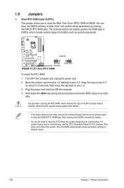
... to pins 2-3. P8Z68-V LX CLRTC 12 23 Normal (Default) P8Z68-V LX Clear RTC RAM Clear RTC To erase the RTC RAM: 1. Plug the power cord and turn ON the computer. 4. Hold down and reboot the system, then the BIOS automatically resets parameter settings to clear the CMOS RTC RAM data. Move the jumper cap from pins...
... to pins 2-3. P8Z68-V LX CLRTC 12 23 Normal (Default) P8Z68-V LX Clear RTC RAM Clear RTC To erase the RTC RAM: 1. Plug the power cord and turn ON the computer. 4. Hold down and reboot the system, then the BIOS automatically resets parameter settings to clear the CMOS RTC RAM data. Move the jumper cap from pins...
User Manual
Page 57
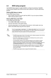
.... Chapter 2: BIOS information 2-7 Entering BIOS Setup after POST To enter BIOS Setup after changing any BIOS setting, try to clear the CMOS and reset the motherboard to your motherboard if you do not press , POST continues with its parameters. We recommend to always shut down... the system properly from a running operating system can cause damage to the default value. Refer to section 1.9 Jumpers on the system chassis. • Press the power button to ensure optimum performance. The BIOS screens include navigation keys and brief online help...
.... Chapter 2: BIOS information 2-7 Entering BIOS Setup after POST To enter BIOS Setup after changing any BIOS setting, try to clear the CMOS and reset the motherboard to your motherboard if you do not press , POST continues with its parameters. We recommend to always shut down... the system properly from a running operating system can cause damage to the default value. Refer to section 1.9 Jumpers on the system chassis. • Press the power button to ensure optimum performance. The BIOS screens include navigation keys and brief online help...
User Manual
Page 61
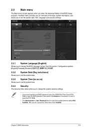
.../2011] [16:46:15] Administrator > Security Choose the system default language →←: Select Screen ↑↓: Select Item Enter: Select +/-: Change Opt. See section 1.9 Jumpers for information on how to erase the RTC RAM. • The Administrator or User Password items on top of the BIOS Setup program. 2.3 Main menu... The Main menu screen appears when you have forgotten your BIOS password, erase the CMOS Real Time Clock (RTC) RAM to clear the BIOS password. EFI BIOS Utility -
.../2011] [16:46:15] Administrator > Security Choose the system default language →←: Select Screen ↑↓: Select Item Enter: Select +/-: Change Opt. See section 1.9 Jumpers for information on how to erase the RTC RAM. • The Administrator or User Password items on top of the BIOS Setup program. 2.3 Main menu... The Main menu screen appears when you have forgotten your BIOS password, erase the CMOS Real Time Clock (RTC) RAM to clear the BIOS password. EFI BIOS Utility -


