

User Manual
Page 10
P8H67-M2 Series specifications summary Back panel I/O ports Internal connectors / buttons / switches BIOS Accessories Support DVD Form factor 1 x PS/2 Keyboard/Mouse combo port 1 x DVI-D port 1 x VGA port 1 x ... connector 1 x 4-pin ATX 12V power connector 1 x System panel connector 1 x TPM IC onboard (P8H67-M2/TPM/SI only) 32 Mb Flash ROM, EFI AMI BIOS, PnP, DMI 2.0, WfM 2.0, ACPI 2.0a, SM BIOS 2.6, Multi-language BIOS 2 x Serial ATA 3.0Gb/s cables 1 x I/O shield 1 x User Manual 1 x Support DVD Drivers ASUS utilities ASUS Update Anti-virus software (OEM version) MicroATX form factor: 9.6 in...
P8H67-M2 Series specifications summary Back panel I/O ports Internal connectors / buttons / switches BIOS Accessories Support DVD Form factor 1 x PS/2 Keyboard/Mouse combo port 1 x DVI-D port 1 x VGA port 1 x ... connector 1 x 4-pin ATX 12V power connector 1 x System panel connector 1 x TPM IC onboard (P8H67-M2/TPM/SI only) 32 Mb Flash ROM, EFI AMI BIOS, PnP, DMI 2.0, WfM 2.0, ACPI 2.0a, SM BIOS 2.6, Multi-language BIOS 2 x Serial ATA 3.0Gb/s cables 1 x I/O shield 1 x User Manual 1 x Support DVD Drivers ASUS utilities ASUS Update Anti-virus software (OEM version) MicroATX form factor: 9.6 in...
User Manual
Page 11
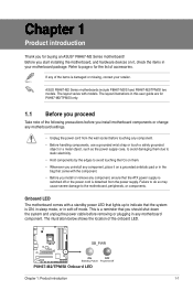
...ON, in sleep mode, or in soft-off mode. SB_PWR P8H67-M2/TPM/SI ON OFF Standby Power Powered Off P8H67-M2/TPM/SI Onboard LED Chapter 1: Product introduction 1-1 The layout illustrations in this user guide are for P8H67-M2/TPM/SI only. 1.1 Before you proceed Take note of the following ...the items is damaged or missing, contact your motherboard package. The illustration below shows the location of accessories. ASUS P8H67-M2 Series motherboards include P8H67-M2/SI and P8H67-M2/TPM/SI two models. Before you for the list of the onboard LED. Onboard LED The motherboard comes with a ...
...ON, in sleep mode, or in soft-off mode. SB_PWR P8H67-M2/TPM/SI ON OFF Standby Power Powered Off P8H67-M2/TPM/SI Onboard LED Chapter 1: Product introduction 1-1 The layout illustrations in this user guide are for P8H67-M2/TPM/SI only. 1.1 Before you proceed Take note of the following ...the items is damaged or missing, contact your motherboard package. The illustration below shows the location of accessories. ASUS P8H67-M2 Series motherboards include P8H67-M2/SI and P8H67-M2/TPM/SI two models. Before you for the list of the onboard LED. Onboard LED The motherboard comes with a ...
User Manual
Page 12
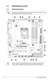
DO NOT overtighten the screws! Doing so can damage the motherboard. 1-2 ASUS P8H67-M2 Series 1.2 1.2.1 Motherboard overview Motherboard layout Ensure that you install the motherboard into the holes indicated by circles to secure the ...(64bit, 240-pin module) VGA LGA1155 24.4cm(9.6in) USB34 EATXPWR LAN1_USB12 Lithium Cell CHA_FAN CMOS Power 2 AUDIO PCIEX16 RTL 8111E P8H67-M2/TPM/SI PCI1 7 SB_PWR 8 TPM IC asmedia ASM1083 PCI2 VIA VT1708S SPDIF_OUT PCIEX1_1 AAFP USB1314 USB1112 USB910 Intel® H67 CHASSIS CLRTC 32Mb BIOS SATA3G_3 SATA3G_1 SATA6G_1 USB78 ...
DO NOT overtighten the screws! Doing so can damage the motherboard. 1-2 ASUS P8H67-M2 Series 1.2 1.2.1 Motherboard overview Motherboard layout Ensure that you install the motherboard into the holes indicated by circles to secure the ...(64bit, 240-pin module) VGA LGA1155 24.4cm(9.6in) USB34 EATXPWR LAN1_USB12 Lithium Cell CHA_FAN CMOS Power 2 AUDIO PCIEX16 RTL 8111E P8H67-M2/TPM/SI PCI1 7 SB_PWR 8 TPM IC asmedia ASM1083 PCI2 VIA VT1708S SPDIF_OUT PCIEX1_1 AAFP USB1314 USB1112 USB910 Intel® H67 CHASSIS CLRTC 32Mb BIOS SATA3G_3 SATA3G_1 SATA6G_1 USB78 ...

User Manual
Page 14
... with less power consumption. The figure illustrates the location of the DDR3 DIMM sockets: DIMM_A1 DIMM_A2 DIMM_B1 DIMM_B2 P8H67-M2/TPM/SI Channel Channel A Channel B Sockets DIMM_A1 and DIMM_A2 DIMM_B1 and DIMM_B2 P8H67-M2/TPM/SI 240-pin DDR3 DIMM sockets 1-4 ASUS P8H67-M2 Series DDR3 modules are developed for better performance with four Double Data Rate 3 (DDR3) Dual Inline Memory...
... with less power consumption. The figure illustrates the location of the DDR3 DIMM sockets: DIMM_A1 DIMM_A2 DIMM_B1 DIMM_B2 P8H67-M2/TPM/SI Channel Channel A Channel B Sockets DIMM_A1 and DIMM_A2 DIMM_B1 and DIMM_B2 P8H67-M2/TPM/SI 240-pin DDR3 DIMM sockets 1-4 ASUS P8H67-M2 Series DDR3 modules are developed for better performance with four Double Data Rate 3 (DDR3) Dual Inline Memory...

User Manual
Page 18
... powers the RAM data in CMOS. After clearing the CMOS, reinstall the battery. 1-8 ASUS P8H67-M2 Series Keep the cap on CLRTC jumper default position. Removing the cap will cause system boot failure! P8H67-M2/TPM/SI CLRTC 12 23 Normal (Default) Clear RTC P8H67-M2/TPM/SI Clear RTC RAM To erase the RTC RAM: 1. Turn OFF the computer and...
... powers the RAM data in CMOS. After clearing the CMOS, reinstall the battery. 1-8 ASUS P8H67-M2 Series Keep the cap on CLRTC jumper default position. Removing the cap will cause system boot failure! P8H67-M2/TPM/SI CLRTC 12 23 Normal (Default) Clear RTC P8H67-M2/TPM/SI Clear RTC RAM To erase the RTC RAM: 1. Turn OFF the computer and...
User Manual
Page 20
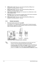
...PIN 1 MIC2 MICPWR Line out_R NC Line out_L PORT1 L PORT1 R PORT2 R SENSE_SEND PORT2 L P8H67-M2/TPM/SI HD-audio-compliant Legacy AC'97 pin definition compliant definition P8H67-M2/TPM/SI Front panel audio connector • We recommend that supports either HD Audio or legacy AC`97 audio ...this connector is for any DVI-D compatible device. These two 4-pin Universal Serial Bus (USB) ports are available for details. 1-10 ASUS P8H67-M2 Series See section 2.5.6 Onboard Devices Configuration for connecting USB 2.0/1.1 devices. 7. This 15-pin port is for a chassis-mounted front ...
...PIN 1 MIC2 MICPWR Line out_R NC Line out_L PORT1 L PORT1 R PORT2 R SENSE_SEND PORT2 L P8H67-M2/TPM/SI HD-audio-compliant Legacy AC'97 pin definition compliant definition P8H67-M2/TPM/SI Front panel audio connector • We recommend that supports either HD Audio or legacy AC`97 audio ...this connector is for any DVI-D compatible device. These two 4-pin Universal Serial Bus (USB) ports are available for details. 1-10 ASUS P8H67-M2 Series See section 2.5.6 Onboard Devices Configuration for connecting USB 2.0/1.1 devices. 7. This 15-pin port is for a chassis-mounted front ...

User Manual
Page 22
... that complies with more power-consuming devices. Digital audio connector (4-1 pin SPDIF_OUT) This connector is purchased separately. 1-12 ASUS P8H67-M2 Series ATX12V EATXPWR +12V DC +12V DC P8H67-M2/TPM/SI GND GND +3 Volts +12 Volts +12 Volts +5V Standby Power OK PIN 1 GND +5 Volts GND +5 Volts... GND +3 Volts +3 Volts PIN 1 GND +5 Volts +5 Volts +5 Volts -5 Volts GND GND GND PSON# GND -12 Volts +3 Volts P8H67-M2/TPM/SI ATX power connectors • For a fully configured system, we recommend that you use a power supply unit (PSU) that you are for your...
... that complies with more power-consuming devices. Digital audio connector (4-1 pin SPDIF_OUT) This connector is purchased separately. 1-12 ASUS P8H67-M2 Series ATX12V EATXPWR +12V DC +12V DC P8H67-M2/TPM/SI GND GND +3 Volts +12 Volts +12 Volts +5V Standby Power OK PIN 1 GND +5 Volts GND +5 Volts... GND +3 Volts +3 Volts PIN 1 GND +5 Volts +5 Volts +5 Volts -5 Volts GND GND GND PSON# GND -12 Volts +3 Volts P8H67-M2/TPM/SI ATX power connectors • For a fully configured system, we recommend that you use a power supply unit (PSU) that you are for your...

User Manual
Page 24
... or later version. • When using hot-plug and NCQ, set using Serial ATA hard disk drives. SPEAKER +5V GND GND Speaker Out P8H67-M2/TPM/SI PIN 1 P8H67-M2/TPM/SI Speaker connector 1-14 ASUS P8H67-M2 Series See section 2.5.4 SATA Configuration for details. 8. 7. In IDE mode, you are set to these connectors, set , refer to the RAID Supplementary Guide...
... or later version. • When using hot-plug and NCQ, set using Serial ATA hard disk drives. SPEAKER +5V GND GND Speaker Out P8H67-M2/TPM/SI PIN 1 P8H67-M2/TPM/SI Speaker connector 1-14 ASUS P8H67-M2 Series See section 2.5.4 SATA Configuration for details. 8. 7. In IDE mode, you are set to these connectors, set , refer to the RAID Supplementary Guide...

User Manual
Page 26
...USB module cable is purchased separately. 1-16 ASUS P8H67-M2 Series Connect the serial port module cable to this connector, then install the module to a slot opening at the back of the system chassis. COM1 PIN 1 P8H67-M2/TPM/SI P8H67-M2/TPM/SI Serial port (COM1) connector The COM module ...NC USB+5V USB_P10USB_P10+ GND NC USB+5V USB_P8USB_P8+ GND NC P8H67-M2/TPM/SI PIN 1 PIN 1 PIN 1 PIN 1 USB+5V USB_P13USB_P13+ GND USB+5V USB_P11USB_P11+ GND USB+5V USB_P9USB_P9+ GND USB+5V USB_P7USB_P7+ GND P8H67-M2/TPM/SI USB2.0 connectors Never connect a 1394 cable to 480 Mbps connection...
...USB module cable is purchased separately. 1-16 ASUS P8H67-M2 Series Connect the serial port module cable to this connector, then install the module to a slot opening at the back of the system chassis. COM1 PIN 1 P8H67-M2/TPM/SI P8H67-M2/TPM/SI Serial port (COM1) connector The COM module ...NC USB+5V USB_P10USB_P10+ GND NC USB+5V USB_P8USB_P8+ GND NC P8H67-M2/TPM/SI PIN 1 PIN 1 PIN 1 PIN 1 USB+5V USB_P13USB_P13+ GND USB+5V USB_P11USB_P11+ GND USB+5V USB_P9USB_P9+ GND USB+5V USB_P7USB_P7+ GND P8H67-M2/TPM/SI USB2.0 connectors Never connect a 1394 cable to 480 Mbps connection...

User Manual
Page 30
... to update the BIOS without using EZ Flash 2: 1. Go to the Tool menu to select ASUS EZ Flash Utility and press to avail all its features. ASUSTek EZ Flash BIOS ROM Utility V00.75 Flash Info MODEL: P8H67-M2/TPM/SI File Path: fs0:\ Drive fs0:\ VER: 0201 Folder Info 03/21/2011 10:23p...
... to update the BIOS without using EZ Flash 2: 1. Go to the Tool menu to select ASUS EZ Flash Utility and press to avail all its features. ASUSTek EZ Flash BIOS ROM Utility V00.75 Flash Info MODEL: P8H67-M2/TPM/SI File Path: fs0:\ Drive fs0:\ VER: 0201 Folder Info 03/21/2011 10:23p...

User Manual
Page 31
...the BIOS update process. DO NOT shut down or reset the system while updating the BIOS to prevent system boot failure! 2.1.3 ASUS CrashFree BIOS 3 utility The ASUS CrashFree BIOS 3 is an auto recovery tool that allows you press to the USB port. 3. Chapter 2: BIOS information 2-3 Press... the Drive field. 4. Download the latest BIOS file from the ASUS website at www.asus.com. The utility automatically checks the devices for P8H67-M2/TPM/SI). • The BIOS file in the removable device into P8H67M2.ROM (for P8H67-M2/SI) or P8H67M2T.ROM (for the BIOS file. To ensure system compatibility...
...the BIOS update process. DO NOT shut down or reset the system while updating the BIOS to prevent system boot failure! 2.1.3 ASUS CrashFree BIOS 3 utility The ASUS CrashFree BIOS 3 is an auto recovery tool that allows you press to the USB port. 3. Chapter 2: BIOS information 2-3 Press... the Drive field. 4. Download the latest BIOS file from the ASUS website at www.asus.com. The utility automatically checks the devices for P8H67-M2/TPM/SI). • The BIOS file in the removable device into P8H67M2.ROM (for P8H67-M2/SI) or P8H67M2T.ROM (for the BIOS file. To ensure system compatibility...

User Manual
Page 34
...; Ensure to load the BIOS default settings to ensure system compatibility and stability. Are you have disconnected them. 2-6 ASUS P8H67-M2 Series Yes No 4. Refer to section 2.9 Exit menu for DOS V1.18 Current ROM BOARD: P8H67-M2/TPM/SI VER: 0201 DATE: 03/21/2011 Update ROM BOARD: Unknown VER: Unknown DATE: Unknown PATH: A:\ A: P8H67M2T.ROM...
...; Ensure to load the BIOS default settings to ensure system compatibility and stability. Are you have disconnected them. 2-6 ASUS P8H67-M2 Series Yes No 4. Refer to section 2.9 Exit menu for DOS V1.18 Current ROM BOARD: P8H67-M2/TPM/SI VER: 0201 DATE: 03/21/2011 Update ROM BOARD: Unknown VER: Unknown DATE: Unknown PATH: A:\ A: P8H67M2T.ROM...

User Manual
Page 36
...; The boot device options vary depending on the devices you to the system. 2-8 ASUS P8H67-M2 Series The EZ Mode provides you an overview of the BIOS setup program Clicks to decide the boot priority. EZ Mode Friday [10/08/2010] P8H67-M2/TPM/SI BIOS Version : 0201 CPU Type : Intel(R) Core(TM) i5-2400 CPU @ 3.10GHz...
...; The boot device options vary depending on the devices you to the system. 2-8 ASUS P8H67-M2 Series The EZ Mode provides you an overview of the BIOS setup program Clicks to decide the boot priority. EZ Mode Friday [10/08/2010] P8H67-M2/TPM/SI BIOS Version : 0201 CPU Type : Intel(R) Core(TM) i5-2400 CPU @ 3.10GHz...

User Manual
Page 56
... Signature : Date : Apr. 11, 2011 Ver. 110101 EC Declaration of the following apparatus: Product name : Motherboard Model name : P8H67-M2/SI, P8H67-M2/TPM/SI conform with part 15 of the FCC Rules. Country: TAIWAN Authorized representative in Europe: ASUS COMPUTER GmbH Address, City: HARKORT STR. 21-23, 40880 RATINGEN Country: GERMANY declare the following directives: 2004/108...
... Signature : Date : Apr. 11, 2011 Ver. 110101 EC Declaration of the following apparatus: Product name : Motherboard Model name : P8H67-M2/SI, P8H67-M2/TPM/SI conform with part 15 of the FCC Rules. Country: TAIWAN Authorized representative in Europe: ASUS COMPUTER GmbH Address, City: HARKORT STR. 21-23, 40880 RATINGEN Country: GERMANY declare the following directives: 2004/108...


