P8H61-I R2.0 User's Manual
Page 2
... is authorized in receipt of this information. No part of this manual, including the products and software described in it shipped to duly provide complete source code as source code archives, etc. ii SPECIFICATIONS AND INFORMATION CONTAINED IN THIS MANUAL ARE FURNISHED FOR INFORMATIONAL USE ONLY, AND ARE SUBJECT TO CHANGE AT ANY TIME WITHOUT NOTICE, AND SHOULD NOT...
... is authorized in receipt of this information. No part of this manual, including the products and software described in it shipped to duly provide complete source code as source code archives, etc. ii SPECIFICATIONS AND INFORMATION CONTAINED IN THIS MANUAL ARE FURNISHED FOR INFORMATIONAL USE ONLY, AND ARE SUBJECT TO CHANGE AT ANY TIME WITHOUT NOTICE, AND SHOULD NOT...
P8H61-I R2.0 User's Manual
Page 3
...(CPU 1-4 1.4 System memory 1-4 1.4.1 Overview 1-4 1.4.2 Memory configurations 1-5 1.5 Expansion slots 1-13 1.5.1 Installing an expansion card 1-13 1.5.2 Configuring an expansion card 1-13 1.5.3 PCI Express x16 slot 1-13 1.6 Jumpers 1-14 1.7 Connectors 1-15 1.7.1 Rear panel connectors 1-15 1.7.2 Internal connectors 1-17 1.8 Software support 1-22 1.8.1 Installing an operating system 1-22 1.8.2 Support DVD information 1-22 Chapter 2 BIOS information 2.1 Managing and updating your BIOS 2-1 2.1.1 ASUS Update utility 2-1 2.1.2 ASUS EZ Flash 2 2-2 2.1.3 ASUS CrashFree BIOS 3 utility...
...(CPU 1-4 1.4 System memory 1-4 1.4.1 Overview 1-4 1.4.2 Memory configurations 1-5 1.5 Expansion slots 1-13 1.5.1 Installing an expansion card 1-13 1.5.2 Configuring an expansion card 1-13 1.5.3 PCI Express x16 slot 1-13 1.6 Jumpers 1-14 1.7 Connectors 1-15 1.7.1 Rear panel connectors 1-15 1.7.2 Internal connectors 1-17 1.8 Software support 1-22 1.8.1 Installing an operating system 1-22 1.8.2 Support DVD information 1-22 Chapter 2 BIOS information 2.1 Managing and updating your BIOS 2-1 2.1.1 ASUS Update utility 2-1 2.1.2 ASUS EZ Flash 2 2-2 2.1.3 ASUS CrashFree BIOS 3 utility...
P8H61-I R2.0 User's Manual
Page 9
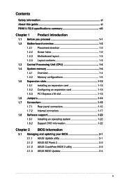
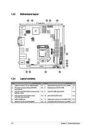
...x USB 3.0/2.0 ports (blue) 3 x Audio jacks 2 x USB 2.0/1.1 connector support additional 4 USB 2.0/1.1 ports 4 x SATA 3.0Gb/s connectors 1 x 4-pin CPU fan connector 1 x 4-pin Chassis fan connector 1 x Front panel audio connector 1 x System panel connector 1 x Clear CMOS jumper 1 x 24-pin EATX power connector 1 x 4-pin ATX 12V power connector 1 x speaker header 1 x S/PDIF out connector 1 x DRCT Header 64 Mb Flash ROM, AMI BIOS, PnP, DMI 2.0, WfM 2.0, ACPI 2.0a, SM BIOS 2.5 WOL by PME, PXE 2 x Serial ATA cables 1 x I/O shield 1 x User Manual 1 x Support DVD Drivers ASUS utilities ASUS Update Anti...
...x USB 3.0/2.0 ports (blue) 3 x Audio jacks 2 x USB 2.0/1.1 connector support additional 4 USB 2.0/1.1 ports 4 x SATA 3.0Gb/s connectors 1 x 4-pin CPU fan connector 1 x 4-pin Chassis fan connector 1 x Front panel audio connector 1 x System panel connector 1 x Clear CMOS jumper 1 x 24-pin EATX power connector 1 x 4-pin ATX 12V power connector 1 x speaker header 1 x S/PDIF out connector 1 x DRCT Header 64 Mb Flash ROM, AMI BIOS, PnP, DMI 2.0, WfM 2.0, ACPI 2.0a, SM BIOS 2.5 WOL by PME, PXE 2 x Serial ATA cables 1 x I/O shield 1 x User Manual 1 x Support DVD Drivers ASUS utilities ASUS Update Anti...
P8H61-I R2.0 User's Manual
Page 13
...; LGA1155 CPU socket 1-13 1-4 11. Front panel audio connector (10-1 pin AAFP) 1-17 1-3 Chapter 1: Product introduction DDR3 U-DIMM slots 6. CPU and chassis fan connectors (4-pin CPU_FAN, 4-pin CHA_FAN) 5. ATX power connectors (24-pin EATXPWR, 1-13 8. Clear RTC RAM (3-pin CLRTC) 1-10 SATA3G_1/2/3/4) 4. USB 2.0 connector (10-1 pin USB78, USB56) 1-17 7. 1.2.3 Motherboard layout 12 34 5 17.1cm(6.75in) KBMS HDMI ASM 1442 USB78 USB56 Intel® H61 SATA3G_1 SATA3G_2 SATA3G_3 SATA3G_4 CPU_FAN CHA_FAN Super I/O 32Mb BIOS Lithium Cell CMOS Power ATX12V...
...; LGA1155 CPU socket 1-13 1-4 11. Front panel audio connector (10-1 pin AAFP) 1-17 1-3 Chapter 1: Product introduction DDR3 U-DIMM slots 6. CPU and chassis fan connectors (4-pin CPU_FAN, 4-pin CHA_FAN) 5. ATX power connectors (24-pin EATXPWR, 1-13 8. Clear RTC RAM (3-pin CLRTC) 1-10 SATA3G_1/2/3/4) 4. USB 2.0 connector (10-1 pin USB78, USB56) 1-17 7. 1.2.3 Motherboard layout 12 34 5 17.1cm(6.75in) KBMS HDMI ASM 1442 USB78 USB56 Intel® H61 SATA3G_1 SATA3G_2 SATA3G_3 SATA3G_4 CPU_FAN CHA_FAN Super I/O 32Mb BIOS Lithium Cell CMOS Power ATX12V...
P8H61-I R2.0 User's Manual
Page 15
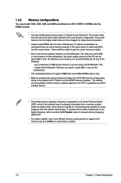
... of accessing information from the same vendor. Profile is dependent on the motherboard. • This motherboard does not support DIMMs that you are using a 32-bit Windows® OS. - Under the default state, some memory modules for overclocking may install varying memory sizes in Channel A and Channel B. For effective use of these memory modules depend on the CPU's capabilities and other installed devices. • The default memory operation frequency is not the JEDEC memory...
... of accessing information from the same vendor. Profile is dependent on the motherboard. • This motherboard does not support DIMMs that you are using a 32-bit Windows® OS. - Under the default state, some memory modules for overclocking may install varying memory sizes in Channel A and Channel B. For effective use of these memory modules depend on the CPU's capabilities and other installed devices. • The default memory operation frequency is not the JEDEC memory...
P8H61-I R2.0 User's Manual
Page 23
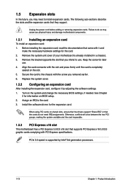
... hardware settings for later use . Turn on BIOS setup. 2. When using PCI cards on the slot. 5. Unplug the power cord before adding or removing expansion cards. Failure to do not need to the chassis with PCI Express specifications. Before installing the expansion card, read the documentation that you physical injury and damage motherboard components. 1.5.1 Installing an expansion card To install an expansion card: 1. Remove the system unit cover (if your motherboard is supported by adjusting the software settings. 1. Remove the...
... hardware settings for later use . Turn on BIOS setup. 2. When using PCI cards on the slot. 5. Unplug the power cord before adding or removing expansion cards. Failure to do not need to the chassis with PCI Express specifications. Before installing the expansion card, read the documentation that you physical injury and damage motherboard components. 1.5.1 Installing an expansion card To install an expansion card: 1. Remove the system unit cover (if your motherboard is supported by adjusting the software settings. 1. Remove the...
P8H61-I R2.0 User's Manual
Page 24
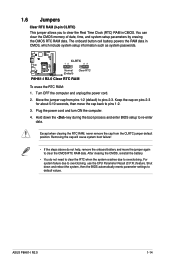
... 23 P8H61-I R2.0 Normal (Default) Clear RTC P8H61-I R2.0 1-14 Hold down and reboot the system, then the BIOS automatically resets parameter settings to clear the CMOS RTC RAM data. Except when clearing the RTC RAM, never remove the cap from pins 1-2 (default) to pins 1-2. 3. For system failure due to re-enter data. Turn OFF the computer and unplug the power cord. 2. Shut down the key during the boot process and enter BIOS setup to overclocking, use the CPU Parameter...
... 23 P8H61-I R2.0 Normal (Default) Clear RTC P8H61-I R2.0 1-14 Hold down and reboot the system, then the BIOS automatically resets parameter settings to clear the CMOS RTC RAM data. Except when clearing the RTC RAM, never remove the cap from pins 1-2 (default) to pins 1-2. 3. For system failure due to re-enter data. Turn OFF the computer and unplug the power cord. 2. Shut down the key during the boot process and enter BIOS setup to overclocking, use the CPU Parameter...
P8H61-I R2.0 User's Manual
Page 28
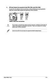
... place jumper caps on the motherboard, ensuring that the black wire of each cable matches the ground pin of the connector. ASUS P8H61-I R2.0 CPU FAN PWM CPU FAN IN CPU FAN PWR GND CHA FAN PWM CPU FAN IN CHA FAN PWR GND 3. P8H61-I R2.0 1-18 Only the 4-pin CPU fan and chassis fan support the ASUS FanXpert feature. Insufficient air flow inside the system may damage the motherboard components. CPU and chassis fan connectors (4-pin CPU_FAN, 4-pin CHA_FAN) Connect the fan cables to the fan connectors. CPU_FAN CHA_FAN P8H61-I R2.0 Fan connectors...
... place jumper caps on the motherboard, ensuring that the black wire of each cable matches the ground pin of the connector. ASUS P8H61-I R2.0 CPU FAN PWM CPU FAN IN CPU FAN PWR GND CHA FAN PWM CPU FAN IN CHA FAN PWR GND 3. P8H61-I R2.0 1-18 Only the 4-pin CPU fan and chassis fan support the ASUS FanXpert feature. Insufficient air flow inside the system may damage the motherboard components. CPU and chassis fan connectors (4-pin CPU_FAN, 4-pin CHA_FAN) Connect the fan cables to the fan connectors. CPU_FAN CHA_FAN P8H61-I R2.0 Fan connectors...
P8H61-I R2.0 User's Manual
Page 31
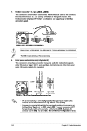
... the motherboard! USB 2.0 connector (10-1 pin USB78, USB56) This connector is purchased separately. 8. See section 2.5.6 Onboard Devices Configuration for a chassis-mounted front panel audio I R2.0 Front panel audio connector • We recommend that supports either HD Audio or legacy AC`97 audio standard. Connect one end of the front panel audio I R2.0 USB2.0 connectors Never connect a 1394 cable to [HD]. By default, this connector, set to the USB connector. Front panel audio connector (10-1 pin AAFP) This connector is set the Front Panel Type item in the BIOS setup to...
... the motherboard! USB 2.0 connector (10-1 pin USB78, USB56) This connector is purchased separately. 8. See section 2.5.6 Onboard Devices Configuration for a chassis-mounted front panel audio I R2.0 Front panel audio connector • We recommend that supports either HD Audio or legacy AC`97 audio standard. Connect one end of the front panel audio I R2.0 USB2.0 connectors Never connect a 1394 cable to [HD]. By default, this connector, set to the USB connector. Front panel audio connector (10-1 pin AAFP) This connector is set the Front Panel Type item in the BIOS setup to...
P8H61-I R2.0 User's Manual
Page 32
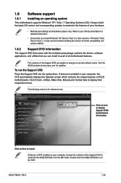
... display Support DVD/ motherboard information Click an item to change at www.asus.com for reference only. To run the DVD. If Autorun is for updates. ASUS P8H61-I R2.0 1-22 1.8 Software support 1.8.1 Installing an operating system This motherboard supports Windows® XP / Vista / 7 Operating Systems (OS). Click Drivers, Utilities, Make Disk, Manual,and Contact tabs to run the Support DVD Place the Support DVD into the optical drive. The following screen is enabled in your computer, the DVD automatically displays...
... display Support DVD/ motherboard information Click an item to change at www.asus.com for reference only. To run the DVD. If Autorun is for updates. ASUS P8H61-I R2.0 1-22 1.8 Software support 1.8.1 Installing an operating system This motherboard supports Windows® XP / Vista / 7 Operating Systems (OS). Click Drivers, Utilities, Make Disk, Manual,and Contact tabs to run the Support DVD Place the Support DVD into the optical drive. The following screen is enabled in your computer, the DVD automatically displays...
P8H61-I R2.0 User's Manual
Page 33
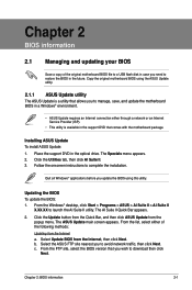
... II utility. Chapter 2 BIOS information 2.1 Managing and updating your BIOS Save a copy of the following methods: Updating from the popup menu. From the list, select either through a network or an Internet Service Provider (ISP). • This utility is a utility that allows you to manage, save, and update the motherboard BIOS in a Windows® environment. • ASUS Update requires an Internet connection either of the original motherboard BIOS file to a USB flash disk in case you...
... II utility. Chapter 2 BIOS information 2.1 Managing and updating your BIOS Save a copy of the following methods: Updating from the popup menu. From the list, select either through a network or an Internet Service Provider (ISP). • This utility is a utility that allows you to manage, save, and update the motherboard BIOS in a Windows® environment. • ASUS Update requires an Internet connection either of the original motherboard BIOS file to a USB flash disk in case you...
P8H61-I R2.0 User's Manual
Page 35
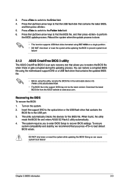
... so can restore a corrupted BIOS file using this utility, rename the BIOS file in the removable device into P8H61-I-R2-ASUS-0306.ROM. • The BIOS file in the support DVD may not be the latest version. Press the Up/Down arrow keys to recover BIOS settings. You can cause system boot failure! Recovering the BIOS To recover the BIOS: 1. When found, the utility reads the BIOS file and enters ASUS EZ Flash 2 utility automatically. 4. The system requires you to the USB port. 3.
... so can restore a corrupted BIOS file using this utility, rename the BIOS file in the removable device into P8H61-I-R2-ASUS-0306.ROM. • The BIOS file in the support DVD may not be the latest version. Press the Up/Down arrow keys to recover BIOS settings. You can cause system boot failure! Recovering the BIOS To recover the BIOS: 1. When found, the utility reads the BIOS file and enters ASUS EZ Flash 2 utility automatically. 4. The system requires you to the USB port. 3.
P8H61-I R2.0 User's Manual
Page 36
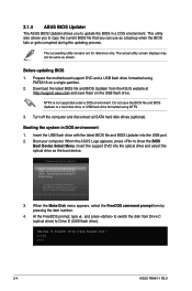
... 1. C:\>d: D:\> 2-4 ASUS P8H61-I R2.0 This utility also allows you to copy the current BIOS file that you to boot using FAT32/16 on the USB flash drive. Turn off the computer and disconnect all SATA hard disk drives (optional). Booting the system in a DOS environment. At the FreeDOS prompt, type d: and press to switch the disk from the ASUS website at http://support.asus.com and save the BIOS file and BIOS Updater to show the BIOS Boot Device Select Menu. Insert the support DVD...
... 1. C:\>d: D:\> 2-4 ASUS P8H61-I R2.0 This utility also allows you to copy the current BIOS file that you to boot using FAT32/16 on the USB flash drive. Turn off the computer and disconnect all SATA hard disk drives (optional). Booting the system in a DOS environment. At the FreeDOS prompt, type d: and press to switch the disk from the ASUS website at http://support.asus.com and save the BIOS file and BIOS Updater to show the BIOS Boot Device Select Menu. Insert the support DVD...
P8H61-I R2.0 User's Manual
Page 38
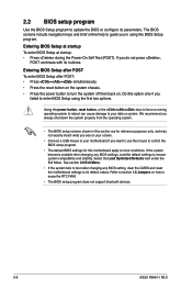
.... Using the power button, reset button, or the ++ keys to force a running operating system to reboot can cause damage to turn the system off then back on. 2.2 BIOS setup program Use the BIOS Setup program to enter BIOS Setup using the BIOS Setup program. Do this motherboard apply to erase the RTC RAM. • The BIOS setup program does not support bluetooth devices. 2-6 ASUS P8H61-I R2.0 The BIOS screens include navigation keys and brief online help to ensure system compatibility and...
.... Using the power button, reset button, or the ++ keys to force a running operating system to reboot can cause damage to turn the system off then back on. 2.2 BIOS setup program Use the BIOS Setup program to enter BIOS Setup using the BIOS Setup program. Do this motherboard apply to erase the RTC RAM. • The BIOS setup program does not support bluetooth devices. 2-6 ASUS P8H61-I R2.0 The BIOS screens include navigation keys and brief online help to ensure system compatibility and...
P8H61-I R2.0 User's Manual
Page 44
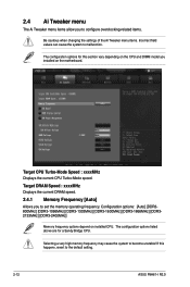
... the Ai Tweaker menu items. Incorrect field values can cause the system to become unstable! Target CPU Turbo-Mode Speed : xxxxMHz Displays the current CPU Turbo-Mode speed. Target DRAM Speed : xxxxMHz Displays the current DRAM speed. 2.4.1 Memory Frequency [Auto] Allows you installed on installed CPU. The configuration options listed above are for this happens, revert to set the memory operating frequency. If this section vary depending on the CPU and DIMM model you to the default setting. 2-12 ASUS P8H61-I R2.0
... the Ai Tweaker menu items. Incorrect field values can cause the system to become unstable! Target CPU Turbo-Mode Speed : xxxxMHz Displays the current CPU Turbo-Mode speed. Target DRAM Speed : xxxxMHz Displays the current DRAM speed. 2.4.1 Memory Frequency [Auto] Allows you installed on installed CPU. The configuration options listed above are for this happens, revert to set the memory operating frequency. If this section vary depending on the CPU and DIMM model you to the default setting. 2-12 ASUS P8H61-I R2.0

P8H61-I R2.0 User's Manual
Page 45
... GPU for extreme graphics performance. Configuration options: [OK] [Cancel] 2.4.3 DRAM Timing Control The sub-items in specific conditions. [Disabled] Disables this happens, revert to become unstable! Use the and keys to adjust the value. To restore the default setting, type [auto] using the keyboard and press . If this function. The operating system dynamically adjusts the processor voltage and core frequency which may cause the system to the default settings. 2.4.4 CPU Power Management The sub...
... GPU for extreme graphics performance. Configuration options: [OK] [Cancel] 2.4.3 DRAM Timing Control The sub-items in specific conditions. [Disabled] Disables this happens, revert to become unstable! Use the and keys to adjust the value. To restore the default setting, type [auto] using the keyboard and press . If this function. The operating system dynamically adjusts the processor voltage and core frequency which may cause the system to the default settings. 2.4.4 CPU Power Management The sub...
P8H61-I R2.0 User's Manual
Page 48
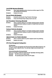
... a hardware platform to perform adjacent cache line prefetching. [Disabled] Disables this function. Execute Disable Bit [Enabled] [Enabled] Enables the No-Execution Page Protection Technology. [Disabled] Forces the XD feature flag to always return to enable or disable the Enhanced Intel® SpeedStep Technology (EIST). [Disabled] The CPU runs at its default speed. [Enabled] The operating system controls the CPU speed. 2-16 ASUS P8H61-I R2.0 Intel Virtualization Technology [Disabled] [Enabled] Allows a hardware platform to run multiple operating systems...
... a hardware platform to perform adjacent cache line prefetching. [Disabled] Disables this function. Execute Disable Bit [Enabled] [Enabled] Enables the No-Execution Page Protection Technology. [Disabled] Forces the XD feature flag to always return to enable or disable the Enhanced Intel® SpeedStep Technology (EIST). [Disabled] The CPU runs at its default speed. [Enabled] The operating system controls the CPU speed. 2-16 ASUS P8H61-I R2.0 Intel Virtualization Technology [Disabled] [Enabled] Allows a hardware platform to run multiple operating systems...

P8H61-I R2.0 User's Manual
Page 51
... (Self-Monitoring, Analysis and Reporting Technology) is installed to set the iGPU memory size. Configuration options: [Enabled] [Disabled] 2.5.4 System Agent Configuration Memory Remap Feature [Enabled] [Enabled] Allow you to decide which graphics controller to H61 Chipset limitations, AHCI Mode only works on random workloads by allowing the drive to report warning messages during the POST. Configuration options: [Auto] [iGPU] [PCIE] iGPU Memory [Auto] Allows you to set the SATA configuration. [IDE Mode] Set to [IDE Mode] when you to the corresponding SATA port...
... (Self-Monitoring, Analysis and Reporting Technology) is installed to set the iGPU memory size. Configuration options: [Enabled] [Disabled] 2.5.4 System Agent Configuration Memory Remap Feature [Enabled] [Enabled] Allow you to decide which graphics controller to H61 Chipset limitations, AHCI Mode only works on random workloads by allowing the drive to report warning messages during the POST. Configuration options: [Auto] [iGPU] [PCIE] iGPU Memory [Auto] Allows you to set the SATA configuration. [IDE Mode] Set to [IDE Mode] when you to the corresponding SATA port...

P8H61-I R2.0 User's Manual
Page 52
...the BIOS setup program. [Auto] Allows the system to enable or disable the internal graphics device's multi-monitor support for USB 3.0 devices on VGA devices. If no USB device is detected, the item shows None. Configuration options: [Disabled] [Enabled] 2.5.5 USB Configuration The items in this menu allow you to enable or disable Render Standby by internal graphics devices. The USB Devices item shows the auto-detected values. EHCI Hand-off feature. [Disabled] Disables the function. 2-20 ASUS P8H61-I R2.0 Legacy USB3.0 Support [Enabled] [Enabled] Enables the support for...
...the BIOS setup program. [Auto] Allows the system to enable or disable the internal graphics device's multi-monitor support for USB 3.0 devices on VGA devices. If no USB device is detected, the item shows None. Configuration options: [Disabled] [Enabled] 2.5.5 USB Configuration The items in this menu allow you to enable or disable Render Standby by internal graphics devices. The USB Devices item shows the auto-detected values. EHCI Hand-off feature. [Disabled] Disables the function. 2-20 ASUS P8H61-I R2.0 Legacy USB3.0 Support [Enabled] [Enabled] Enables the support for...

P8H61-I R2.0 User's Manual
Page 56
... Q-Fan control feature. Chassis Fan Speed Low Limit [600 RPM] This item appears only when you enable the Chassis Q-Fan Control feature and allows you to enable or disable the Anti Surge function. Configuration options: [Disabled] [Enabled] 2-24 ASUS P8H61-I R2.0 Select Ignore if you do not want to detect this item. 2.6.6 Anti Surge Support [Enabled] This item allows you to achieve maximum CPU fan speed. 2.6.4 [Disabled] [Enabled] Chassis Q-Fan Control [Enabled] Disables the Chassis Q-Fan control feature. 2.6.3 [Disabled] [Enabled] CPU Q-Fan Control [Enabled] Disables the CPU Q-Fan...
... Q-Fan control feature. Chassis Fan Speed Low Limit [600 RPM] This item appears only when you enable the Chassis Q-Fan Control feature and allows you to enable or disable the Anti Surge function. Configuration options: [Disabled] [Enabled] 2-24 ASUS P8H61-I R2.0 Select Ignore if you do not want to detect this item. 2.6.6 Anti Surge Support [Enabled] This item allows you to achieve maximum CPU fan speed. 2.6.4 [Disabled] [Enabled] Chassis Q-Fan Control [Enabled] Disables the Chassis Q-Fan control feature. 2.6.3 [Disabled] [Enabled] CPU Q-Fan Control [Enabled] Disables the CPU Q-Fan...


