User Guide
Page 3
Contents Notices...vi Safety information vii About this guide viii P7P55 LX specifications summary x Chapter 1: Product introduction 1.1 Welcome 1-1 1.2 Package contents 1-1 1.3 Special features 1-1 1.3.1 Product highlights 1-1 1.3.2 Innovative ASUS features 1-2 1.4 Before you proceed 1-5 1.5 Motherboard overview 1-6 1.5.1 Placement direction 1-6 1.5.2 Screw holes 1-6 1.5.3 Motherboard layout 1-7 1.5.4 Layout contents 1-7 1.6 Central Processing Unit (CPU 1-8 1.6.1 Installing the CPU 1-8 1.6.2 Installing the CPU heatsink and fan 1-11 1.6.3 Uninstalling...
Contents Notices...vi Safety information vii About this guide viii P7P55 LX specifications summary x Chapter 1: Product introduction 1.1 Welcome 1-1 1.2 Package contents 1-1 1.3 Special features 1-1 1.3.1 Product highlights 1-1 1.3.2 Innovative ASUS features 1-2 1.4 Before you proceed 1-5 1.5 Motherboard overview 1-6 1.5.1 Placement direction 1-6 1.5.2 Screw holes 1-6 1.5.3 Motherboard layout 1-7 1.5.4 Layout contents 1-7 1.6 Central Processing Unit (CPU 1-8 1.6.1 Installing the CPU 1-8 1.6.2 Installing the CPU heatsink and fan 1-11 1.6.3 Uninstalling...
User Guide
Page 6
.... REACH Complying with manufacturer's instructions, may cause undesired operation. DO NOT throw the motherboard in our products at ASUS REACH website at http://green.asus.com/english/REACH.htm. This symbol of the crossed out wheeled bin indicates that the battery should not be placed...complies with Part 15 of the FCC Rules. Canadian Department of electronic products. Check local regulations for help. Changes or modifications to this unit not expressly approved by one or more of the following two conditions: • This device may not cause harmful interference, and •...
.... REACH Complying with manufacturer's instructions, may cause undesired operation. DO NOT throw the motherboard in our products at ASUS REACH website at http://green.asus.com/english/REACH.htm. This symbol of the crossed out wheeled bin indicates that the battery should not be placed...complies with Part 15 of the FCC Rules. Canadian Department of electronic products. Check local regulations for help. Changes or modifications to this unit not expressly approved by one or more of the following two conditions: • This device may not cause harmful interference, and •...
User Guide
Page 20
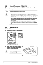
... the PnP cap/socket contacts/motherboard components. P7P55 LX P7P55 LX socket LGA1156 2. 1.6 Central Processing Unit (CPU) The motherboard comes with the cap on the motherboard. To prevent damage to the socket contacts resulting from the retention tab. ASUS will shoulder the cost of repair only if...all power cables before installing the CPU. • Upon purchase of the PnP cap. 1.6.1 Installing the CPU To install a CPU: 1. ASUS will process Return Merchandise Authorization (RMA) requests only if the motherboard comes with a surface mount LGA1156 socket designed for the Intel® ...
... the PnP cap/socket contacts/motherboard components. P7P55 LX P7P55 LX socket LGA1156 2. 1.6 Central Processing Unit (CPU) The motherboard comes with the cap on the motherboard. To prevent damage to the socket contacts resulting from the retention tab. ASUS will shoulder the cost of repair only if...all power cables before installing the CPU. • Upon purchase of the PnP cap. 1.6.1 Installing the CPU To install a CPU: 1. ASUS will process Return Merchandise Authorization (RMA) requests only if the motherboard comes with a surface mount LGA1156 socket designed for the Intel® ...
User Guide
Page 31
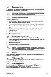
Remove the system unit cover (if your motherboard is completely seated on BIOS setup. 2. Remove the bracket opposite the slot that you intend to use . 4. Replace the system cover. 1.8.2 ... that support PCI Express x16 2.0 graphic cards complying with the screw you removed earlier. 6. Assign an IRQ to section 1.2 Motherboard Overview for the expansion card. ASUS P7P55 LX 1-19 Refer to the card. 3. 1.8 Expansion slots In the future, you may cause you physical injury and damage motherboard components. 1.8.1 Installing an expansion card To...
Remove the system unit cover (if your motherboard is completely seated on BIOS setup. 2. Remove the bracket opposite the slot that you intend to use . 4. Replace the system cover. 1.8.2 ... that support PCI Express x16 2.0 graphic cards complying with the screw you removed earlier. 6. Assign an IRQ to section 1.2 Motherboard Overview for the expansion card. ASUS P7P55 LX 1-19 Refer to the card. 3. 1.8 Expansion slots In the future, you may cause you physical injury and damage motherboard components. 1.8.1 Installing an expansion card To...
User Guide
Page 38
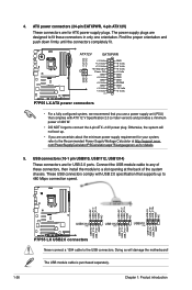
...GND GND GND PSON# GND -12 Volts +3 Volts GND GND P7P55 LX ATX power connectors • For a fully configured system, we recommend that complies with USB 2.0 specification that supports up . • If you use a power supply unit (PSU) that you are for details. 5. Otherwise, the ...1 USB910 PIN 1 USB+5V USB_P9USB_P9+ GND USB+5V USB_P11USB_P11+ GND USB+5V USB_P13USB_P13+ GND P7P55 LX USB2.0 connectors Never connect a 1394 cable to a slot opening at http://support.asus. ATX power connectors (24-pin EATXPWR, 4-pin ATX12V) These connectors are designed to fit these ...
...GND GND GND PSON# GND -12 Volts +3 Volts GND GND P7P55 LX ATX power connectors • For a fully configured system, we recommend that complies with USB 2.0 specification that supports up . • If you use a power supply unit (PSU) that you are for details. 5. Otherwise, the ...1 USB910 PIN 1 USB+5V USB_P9USB_P9+ GND USB+5V USB_P11USB_P11+ GND USB+5V USB_P13USB_P13+ GND P7P55 LX USB2.0 connectors Never connect a 1394 cable to a slot opening at http://support.asus. ATX power connectors (24-pin EATXPWR, 4-pin ATX12V) These connectors are designed to fit these ...


