User Manual
Page 4
... PCI Express x1 slot 2-19 2.5.8 PCI slots 2-19 2.5.9 PIKE slot 2-19 2.5.10 Installing an ASUS PIKE RAID card 2-20 2.5.11 Installing i Button 2-21 2.5.12 Installing ASMB4 management board 2-21 2.5....3.2.1 Using the OS shut down function 3-4 3.2.2 Using the dual function power switch 3-4 Chapter 4: BIOS setup 4.1 Managing and updating your BIOS 4-3 4.1.1 ASUS EZ Flash 2 utility 4-3 4.1.2 BUPDATER utility 4-4 4.1.3 ASUS CrashFree BIOS 3 utility 4-6 4.2 BIOS setup program 4-7 4.2.1 BIOS menu screen 4-8 4.2.2 Menu bar 4-8 4.2.3 Navigation keys 4-8 4.2.4 Menu items 4-9 4.2.5 Sub-menu...
... PCI Express x1 slot 2-19 2.5.8 PCI slots 2-19 2.5.9 PIKE slot 2-19 2.5.10 Installing an ASUS PIKE RAID card 2-20 2.5.11 Installing i Button 2-21 2.5.12 Installing ASMB4 management board 2-21 2.5....3.2.1 Using the OS shut down function 3-4 3.2.2 Using the dual function power switch 3-4 Chapter 4: BIOS setup 4.1 Managing and updating your BIOS 4-3 4.1.1 ASUS EZ Flash 2 utility 4-3 4.1.2 BUPDATER utility 4-4 4.1.3 ASUS CrashFree BIOS 3 utility 4-6 4.2 BIOS setup program 4-7 4.2.1 BIOS menu screen 4-8 4.2.2 Menu bar 4-8 4.2.3 Navigation keys 4-8 4.2.4 Menu items 4-9 4.2.5 Sub-menu...
User Manual
Page 5
... Support [Enabled 4-30 4.6.2 APM Configuration 4-30 4.6.3 Hardware Monitor 4-32 4.7 Boot menu 4-33 4.7.1 Boot Device Priority 4-33 4.7.2 Boot Settings Configuration 4-34 4.7.3 Security 4-35 4.8 Tools menu 4-37 4.8.1 ASUS EZ Flash 2 4-37 4.9 Exit menu 4-38 Chapter 5: RAID configuration 5.1 Setting up RAID 5-3 5.1.1 RAID definitions 5-3 5.1.2 Installing hard disk drives 5-4 5.1.3 Setting the RAID item in...
... Support [Enabled 4-30 4.6.2 APM Configuration 4-30 4.6.3 Hardware Monitor 4-32 4.7 Boot menu 4-33 4.7.1 Boot Device Priority 4-33 4.7.2 Boot Settings Configuration 4-34 4.7.3 Security 4-35 4.8 Tools menu 4-37 4.8.1 ASUS EZ Flash 2 4-37 4.9 Exit menu 4-38 Chapter 5: RAID configuration 5.1 Setting up RAID 5-3 5.1.1 RAID definitions 5-3 5.1.2 Installing hard disk drives 5-4 5.1.3 Setting the RAID item in...
User Manual
Page 6
...Non-RAID 5-30 5.3.5 5.3.6 Recovery Volume Options 5-31 Exiting the Intel® Matrix Storage Manager 5-32 5.3.7 Rebuilding the RAID 5-32 5.3.8 Setting the Boot array in the BIOS Setup Utility 5-34 Chapter 6: Driver installation 6.1 RAID driver installation 6-3 6.1.1 Creating a RAID driver disk 6-3 6.1.2 Installing the RAID controller driver 6-6 6.2 Intel® chipset device... Running the support DVD 6-26 6.5.2 Drivers menu 6-26 6.5.3 Utilities menu 6-27 6.5.4 Make disk menu 6-27 6.5.5 Contact information 6-27 Appendix: Reference information A.1 P7F-E block diagram A-3 vi
...Non-RAID 5-30 5.3.5 5.3.6 Recovery Volume Options 5-31 Exiting the Intel® Matrix Storage Manager 5-32 5.3.7 Rebuilding the RAID 5-32 5.3.8 Setting the Boot array in the BIOS Setup Utility 5-34 Chapter 6: Driver installation 6.1 RAID driver installation 6-3 6.1.1 Creating a RAID driver disk 6-3 6.1.2 Installing the RAID controller driver 6-6 6.2 Intel® chipset device... Running the support DVD 6-26 6.5.2 Drivers menu 6-26 6.5.3 Utilities menu 6-27 6.5.4 Make disk menu 6-27 6.5.5 Contact information 6-27 Appendix: Reference information A.1 P7F-E block diagram A-3 vi
User Manual
Page 9
Detailed descriptions of the BIOS parameters are not part of the switches, jumpers, and connectors on ASUS hardware and software products. ASUS websites The ASUS website provides updated information on the motherboard. • Chapter 3: Powering up This chapter describes the power up , creating, ...system. • Chapter 4: BIOS setup This chapter tells how to the ASUS contact information. 2. These documents are also provided. • Chapter 5: RAID configuration This chapter provides instructions for setting up sequence and ways of the motherboard and the new technologies it ...
Detailed descriptions of the BIOS parameters are not part of the switches, jumpers, and connectors on ASUS hardware and software products. ASUS websites The ASUS website provides updated information on the motherboard. • Chapter 3: Powering up This chapter describes the power up , creating, ...system. • Chapter 4: BIOS setup This chapter tells how to the ASUS contact information. 2. These documents are also provided. • Chapter 5: RAID configuration This chapter provides instructions for setting up sequence and ways of the motherboard and the new technologies it ...
User Manual
Page 25
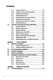
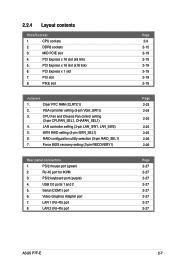
... utility selection (3-pin RAID_SEL1) 7. Force BIOS recovery setting (3-pin RECOVERY1) Rear panel connectors 1. LAN 1 (RJ-45) port 8. LAN 2 (RJ-45) port Page 2-9 2-15 2-19 2-19 2-19 2-19 2-19 2-19 Page 2-23 2-24 2-24 2-25 2-25 2-26 2-26 Page 2-27 2-27 2-27 2-27 2-27 2-27 2-27 2-27 ASUS P7F-E 2-7 2.2.4 Layout contents Slots/Soocket 1. MIO...
... utility selection (3-pin RAID_SEL1) 7. Force BIOS recovery setting (3-pin RECOVERY1) Rear panel connectors 1. LAN 1 (RJ-45) port 8. LAN 2 (RJ-45) port Page 2-9 2-15 2-19 2-19 2-19 2-19 2-19 2-19 Page 2-23 2-24 2-24 2-25 2-25 2-26 2-26 Page 2-27 2-27 2-27 2-27 2-27 2-27 2-27 2-27 ASUS P7F-E 2-7 2.2.4 Layout contents Slots/Soocket 1. MIO...
User Manual
Page 35
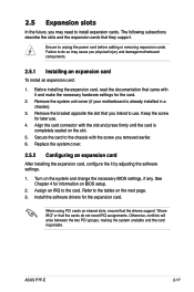
...adjusting the software settings. 1. Remove the system unit cover (if your motherboard is completely seated on shared slots, ensure that the drivers support "Share IRQ" or that they support. Turn on BIOS setup. 2. ASUS P7F-E 2-17 Replace the system cover. 2.5.2 Configuring an expansion card After ... power cord before adding or removing expansion cards. Install the software drivers for information on the system and change the necessary BIOS settings, if any. When using PCI cards on the slot. 5. The following subsections describe the slots and the expansion cards...
...adjusting the software settings. 1. Remove the system unit cover (if your motherboard is completely seated on shared slots, ensure that the drivers support "Share IRQ" or that they support. Turn on BIOS setup. 2. ASUS P7F-E 2-17 Replace the system cover. 2.5.2 Configuring an expansion card After ... power cord before adding or removing expansion cards. Install the software drivers for information on the system and change the necessary BIOS settings, if any. When using PCI cards on the slot. 5. The following subsections describe the slots and the expansion cards...
User Manual
Page 41
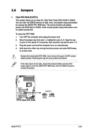
..., never remove the cap on automatically. 4. Turn OFF the computer and unplug the power cord. 2. Hold down the key during the boot process and enter BIOS setup to pins 2-3. If the steps above do not help, remove the onboard battery and move the cap back to pins 1-2. 3. 2.6 Jumpers 1. Clear RTC RAM... seconds, then move the jumper again to clear the Real Time Clock (RTC) RAM in CMOS, which include system setup information such as system passwords. ASUS P7F-E 2-23
..., never remove the cap on automatically. 4. Turn OFF the computer and unplug the power cord. 2. Hold down the key during the boot process and enter BIOS setup to pins 2-3. If the steps above do not help, remove the onboard battery and move the cap back to pins 1-2. 3. 2.6 Jumpers 1. Clear RTC RAM... seconds, then move the jumper again to clear the Real Time Clock (RTC) RAM in CMOS, which include system setup information such as system passwords. ASUS P7F-E 2-23
User Manual
Page 44
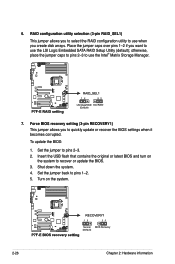
... the jumper caps to pins 2-3 to use when you to select the RAID configuration utility to quickly update or recover the BIOS settings when it becomes corrupted. To update the BIOS: 1. Set the jumper to pins 1-2. 5. Place the jumper caps over pins 1-2 if you to use the Intel®...to use the LSI Logic Embedded SATA RAID Setup Utility (default); Force BIOS recovery setting (3-pin RECOVERY1) This jumper allows you want to recover or update the BIOS. 3. Insert the USB flash that contains the original or latest BIOS and turn on the system. 2-26 Chapter 2: Hardware information Set ...
... the jumper caps to pins 2-3 to use when you to select the RAID configuration utility to quickly update or recover the BIOS settings when it becomes corrupted. To update the BIOS: 1. Set the jumper to pins 1-2. 5. Place the jumper caps over pins 1-2 if you to use the Intel®...to use the LSI Logic Embedded SATA RAID Setup Utility (default); Force BIOS recovery setting (3-pin RECOVERY1) This jumper allows you want to recover or update the BIOS. 3. Insert the USB flash that contains the original or latest BIOS and turn on the system. 2-26 Chapter 2: Hardware information Set ...
User Manual
Page 53
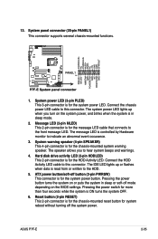
... LED (3-pin PLED) This 3-pin connector is for the system power LED. The speaker allows you turn on the BIOS settings. System warning speaker (4-pin SPEAKER) This 4-pin connector is for the chassis-mounted system warning speaker. The IDE...connects to this connector. Pressing the power button turns the system on or puts the system in sleep mode. 2. ATX power button/soft-off mode depending on the system power, and blinks when the system is for the system power... in sleep or soft-off button (2-pin PWRSW) This connector is ON turns the system OFF. 6. ASUS P7F-E 2-35
... LED (3-pin PLED) This 3-pin connector is for the system power LED. The speaker allows you turn on the BIOS settings. System warning speaker (4-pin SPEAKER) This 4-pin connector is for the chassis-mounted system warning speaker. The IDE...connects to this connector. Pressing the power button turns the system on or puts the system in sleep mode. 2. ATX power button/soft-off mode depending on the system power, and blinks when the system is for the system power... in sleep or soft-off button (2-pin PWRSW) This connector is ON turns the system OFF. 6. ASUS P7F-E 2-35
User Manual
Page 57
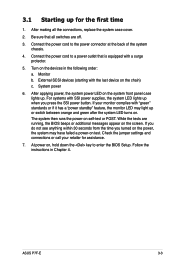
... system then runs the power-on test. If you do not see anything within 30 seconds from the time you press the SSI power button. ASUS P7F-E 3-3 Connect the power cord to a power outlet that all the connections, replace the system case cover. 2. External SCSI devices (starting with a surge protector. ... power, the system may light up . Be sure that is equipped with the last device on the chain) c. Connect the power cord to enter the BIOS Setup. Monitor b. For systems with "green" standards or if it has a "power standby" feature, the monitor LED may have failed a power-on ...
... system then runs the power-on test. If you do not see anything within 30 seconds from the time you press the SSI power button. ASUS P7F-E 3-3 Connect the power cord to a power outlet that all the connections, replace the system case cover. 2. External SCSI devices (starting with a surge protector. ... power, the system may light up . Be sure that is equipped with the last device on the chain) c. Connect the power cord to enter the BIOS Setup. Monitor b. For systems with "green" standards or if it has a "power standby" feature, the monitor LED may have failed a power-on ...

User Manual
Page 58
... Planned check box is ON, pressing the power switch for less than four seconds lets the system enter the soft-off mode regardless of the BIOS setting. Refer to section 4.5 Power Menu in comments. 7. Pressing the power switch for details. 3-4 Chapter 3: Powering up list box. 3. Select Shut Down from the list... Down. 2. If necessary, key in Chapter 4 for more than four seconds puts the system to sleep mode or to soft-off mode, depending on the BIOS setting.
... Planned check box is ON, pressing the power switch for less than four seconds lets the system enter the soft-off mode regardless of the BIOS setting. Refer to section 4.5 Power Menu in comments. 7. Pressing the power switch for details. 3-4 Chapter 3: Powering up list box. 3. Select Shut Down from the list... Down. 2. If necessary, key in Chapter 4 for more than four seconds puts the system to sleep mode or to soft-off mode, depending on the BIOS setting.

User Manual
Page 59
This chapter tells how to change the system settings through the BIOS Setup BIOS se4tup menus. Detailed descriptions of the BIOS parameters are also provided.
This chapter tells how to change the system settings through the BIOS Setup BIOS se4tup menus. Detailed descriptions of the BIOS parameters are also provided.
User Manual
Page 60
Chapter summary 4 4.1 Managing and updating your BIOS 4-1 4.2 BIOS setup program 4-7 4.3 Main menu 4-10 4.4 Advanced menu 4-16 4.5 Server menu 4-28 4.6 Power menu 4-30 4.7 Boot menu 4-33 4.8 Tools menu 4-37 4.9 Exit menu 4-38 ASUS P7F-E
Chapter summary 4 4.1 Managing and updating your BIOS 4-1 4.2 BIOS setup program 4-7 4.3 Main menu 4-10 4.4 Advanced menu 4-16 4.5 Server menu 4-28 4.6 Power menu 4-30 4.7 Boot menu 4-33 4.8 Tools menu 4-37 4.9 Exit menu 4-38 ASUS P7F-E
User Manual
Page 61
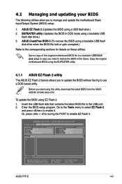
... [V] Drive Info [Esc] Exit ASUS P7F-E 4-3 Copy the original motherboard BIOS using the BUPDATER utility. 4.1.1 ASUS EZ Flash 2 utility The ASUS EZ Flash 2 feature allows you start using this utility, download the latest BIOS from the ASUS website at www.asus.com. Or, press + during the POST to the USB port. 2. ASUS CrashFree BIOS 3 (To recover the BIOS using a USB flash disk...
... [V] Drive Info [Esc] Exit ASUS P7F-E 4-3 Copy the original motherboard BIOS using the BUPDATER utility. 4.1.1 ASUS EZ Flash 2 utility The ASUS EZ Flash 2 feature allows you start using this utility, download the latest BIOS from the ASUS website at www.asus.com. Or, press + during the POST to the USB port. 2. ASUS CrashFree BIOS 3 (To recover the BIOS using a USB flash disk...

User Manual
Page 62
...BIOS file. Save the BIOS file to ensure system compatibility and stability. A:\>BUPDATER /i[file name].ROM 4-4 Chapter 4: BIOS setup Updating the BIOS file To update the BIOS...BIOS to update the BIOS file in DOS mode, then at support.asus.com to switch between drives until the correct BIOS file is found , EZ Flash 2 performs the BIOS...BUPDATER utility (BUPDATER.exe) from the ASUS support website at the prompt, type:... the latest or the original BIOS file on the bootable�U&#... Visit the ASUS website at www.asus.com and download the latest BIOS file for reference only...
...BIOS file. Save the BIOS file to ensure system compatibility and stability. A:\>BUPDATER /i[file name].ROM 4-4 Chapter 4: BIOS setup Updating the BIOS file To update the BIOS...BIOS to update the BIOS file in DOS mode, then at support.asus.com to switch between drives until the correct BIOS file is found , EZ Flash 2 performs the BIOS...BUPDATER utility (BUPDATER.exe) from the ASUS support website at the prompt, type:... the latest or the original BIOS file on the bootable�U&#... Visit the ASUS website at www.asus.com and download the latest BIOS file for reference only...

User Manual
Page 63
Do not turn off power during flash BIOS Note Writing BIOS: DO NOT shut down or reset the system while updating the BIOS to the DOS prompt after the BIOS update process is finished! The utility returns to prevent system boot failure! 5. C:\> ASUS P7F-E 4-5 Please restart your system. Reboot the system from the hard disk drive. The...
Do not turn off power during flash BIOS Note Writing BIOS: DO NOT shut down or reset the system while updating the BIOS to the DOS prompt after the BIOS update process is finished! The utility returns to prevent system boot failure! 5. C:\> ASUS P7F-E 4-5 Please restart your system. Reboot the system from the hard disk drive. The...
User Manual
Page 64
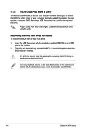
... on the system. 2. You can update a corrupted BIOS file using this motherboard. It resets the system when the BIOS recovery finished. The recovered BIOS may not be the latest BIOS version for this utility. 4.1.3 ASUS CrashFree BIOS 3 utility The ASUS CrashFree BIOS 3 is an auto recovery tool that contains the updated BIOS file. Prepare a USB flash drive containing the updated...
... on the system. 2. You can update a corrupted BIOS file using this motherboard. It resets the system when the BIOS recovery finished. The recovered BIOS may not be the latest BIOS version for this utility. 4.1.3 ASUS CrashFree BIOS 3 utility The ASUS CrashFree BIOS 3 is an auto recovery tool that contains the updated BIOS file. Prepare a USB flash drive containing the updated...
User Manual
Page 65
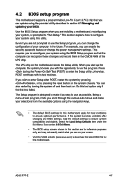
... start up the computer, the system provides you to reconfigure your screen. • Visit the ASUS website (www.asus.com) to download the latest BIOS file for this motherboard. Do this section are for most conditions to run this utility. This section explains how to...menu-driven program, it as possible. ASUS P7F-E 4-7 otherwise, POST continues with the opportunity to ensure optimum performance. The Setup program is designed to make your system, or prompted to ensure system compatibility and stability. Use the BIOS Setup program when you scroll through the...
... start up the computer, the system provides you to reconfigure your screen. • Visit the ASUS website (www.asus.com) to download the latest BIOS file for this motherboard. Do this section are for most conditions to run this utility. This section explains how to...menu-driven program, it as possible. ASUS P7F-E 4-7 otherwise, POST continues with the opportunity to ensure optimum performance. The Setup program is designed to make your system, or prompted to ensure system compatibility and stability. Use the BIOS Setup program when you scroll through the...
User Manual
Page 66
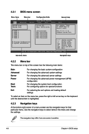
... Menu items Menu bar Configuration fields General help Main Advanced BIOS SETUP UTILITY Server Power Boot Tools Exit System Time [13:44:30] System Date [Wed, 08/05/2009] SATA 1 SATA 2 SATA 3 SATA 4 SATA 5 SATA 6 : [...ST3160812AS] : [Not Detected] : [Not Detected] : [Not Detected] : [Not Detected] : [Not Detected] Storage Configuration System Information Use [ENTER], [TAB] or [SHIFT-TAB] to another. 4-8 Chapter 4: BIOS setup Sub-menu items Navigation keys 4.2.2 Menu bar The menu bar on top of the screen has the following main items: Main Advanced Server Power...
... Menu items Menu bar Configuration fields General help Main Advanced BIOS SETUP UTILITY Server Power Boot Tools Exit System Time [13:44:30] System Date [Wed, 08/05/2009] SATA 1 SATA 2 SATA 3 SATA 4 SATA 5 SATA 6 : [...ST3160812AS] : [Not Detected] : [Not Detected] : [Not Detected] : [Not Detected] : [Not Detected] Storage Configuration System Information Use [ENTER], [TAB] or [SHIFT-TAB] to another. 4-8 Chapter 4: BIOS setup Sub-menu items Navigation keys 4.2.2 Menu bar The menu bar on top of the screen has the following main items: Main Advanced Server Power...
User Manual
Page 68
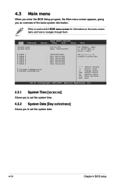
...61 (C)Copyright 1985-2009, American Megatrends, Inc. 4.3.1 System Time [xx:xx:xx] Allows you to set the system date. 4-10 Chapter 4: BIOS setup Main Advanced BIOS SETUP UTILITY Server Power Boot Tools Exit System Time [13:44:30] System Date [Wed, 08/05/2009] SATA 1 SATA 2 SATA 3 SATA...Date [Day xx/xx/xxxx] Allows you an overview of the basic system information. Use [+] or [-] to navigate through them. Refer to section 4.2.1 BIOS menu screen for information on the menu screen items and how to configure system Date. ←→ Select Screen ↑↓ Select Item +- 4.3 ...
...61 (C)Copyright 1985-2009, American Megatrends, Inc. 4.3.1 System Time [xx:xx:xx] Allows you to set the system date. 4-10 Chapter 4: BIOS setup Main Advanced BIOS SETUP UTILITY Server Power Boot Tools Exit System Time [13:44:30] System Date [Wed, 08/05/2009] SATA 1 SATA 2 SATA 3 SATA...Date [Day xx/xx/xxxx] Allows you an overview of the basic system information. Use [+] or [-] to navigate through them. Refer to section 4.2.1 BIOS menu screen for information on the menu screen items and how to configure system Date. ←→ Select Screen ↑↓ Select Item +- 4.3 ...


