User Manual
Page 4
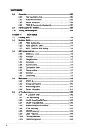
... (system panel 2-37 2.9 Starting up for the first time 2-38 2.10 Turning off the computer 2-38 Chapter 3: BIOS setup 3.1 Knowing BIOS 3-1 3.2 Updating BIOS 3-1 3.2.1 ASUS Update utility 3-2 3.2.2 ASUS EZ Flash 2 utility 3-4 3.2.3 ASUS CrashFree BIOS 3 utility 3-5 3.3 BIOS setup program 3-6 3.3.1 BIOS menu screen 3-6 3.3.2 Menu bar 3-6 3.3.3 Navigation keys 3-7 3.3.4 Menu items 3-7 3.3.5 Submenu items 3-7 3.3.6 Configuration fields 3-7 3.3.7 Pop-up window 3-7 3.3.8 Scroll bar 3-7 3.3.9 General help 3-7 3.4 Main menu...
... (system panel 2-37 2.9 Starting up for the first time 2-38 2.10 Turning off the computer 2-38 Chapter 3: BIOS setup 3.1 Knowing BIOS 3-1 3.2 Updating BIOS 3-1 3.2.1 ASUS Update utility 3-2 3.2.2 ASUS EZ Flash 2 utility 3-4 3.2.3 ASUS CrashFree BIOS 3 utility 3-5 3.3 BIOS setup program 3-6 3.3.1 BIOS menu screen 3-6 3.3.2 Menu bar 3-6 3.3.3 Navigation keys 3-7 3.3.4 Menu items 3-7 3.3.5 Submenu items 3-7 3.3.6 Configuration fields 3-7 3.3.7 Pop-up window 3-7 3.3.8 Scroll bar 3-7 3.3.9 General help 3-7 3.4 Main menu...
User Manual
Page 6
... Probe II 4-3 4.3.2 ASUS AI Suite 4-4 4.3.3 ASUS EPU 4-5 4.3.4 ASUS Fan Xpert 4-6 4.3.5 ASUS TurboV 4-7 4.3.6 ASUS Express Gate SSD 4-8 4.3.7 Audio configurations 4-9 4.4 RAID configurations 4-10 4.4.1 RAID definitions 4-10 4.4.2 Installing Serial ATA hard disks 4-11 4.4.3 Setting the RAID item in BIOS 4-11 4.4.4 Intel® Matrix Storage Manager option ROM utility 4-11 4.5 Creating a RAID driver disk 4-15 4.5.1 Creating a RAID driver disk without...
... Probe II 4-3 4.3.2 ASUS AI Suite 4-4 4.3.3 ASUS EPU 4-5 4.3.4 ASUS Fan Xpert 4-6 4.3.5 ASUS TurboV 4-7 4.3.6 ASUS Express Gate SSD 4-8 4.3.7 Audio configurations 4-9 4.4 RAID configurations 4-10 4.4.1 RAID definitions 4-10 4.4.2 Installing Serial ATA hard disks 4-11 4.4.3 Setting the RAID item in BIOS 4-11 4.4.4 Intel® Matrix Storage Manager option ROM utility 4-11 4.5 Creating a RAID driver disk 4-15 4.5.1 Creating a RAID driver disk without...
User Manual
Page 9
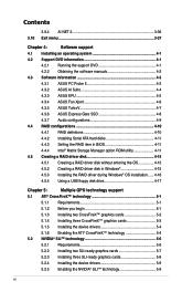
...of the switches, jumpers, and connectors on ASUS hardware and software products. ASUS websites The ASUS website provides updated information on the motherboard. • Chapter 3: BIOS setup This chapter tells how to change system settings through the BIOS Setup menus. ix How this guide This ...; SLI™ graphics cards. Where to find more information Refer to perform when installing system components. Detailed descriptions of the BIOS parameters are not part of the motherboard and the new technology it supports. • Chapter 2: Hardware information This chapter lists...
...of the switches, jumpers, and connectors on ASUS hardware and software products. ASUS websites The ASUS website provides updated information on the motherboard. • Chapter 3: BIOS setup This chapter tells how to change system settings through the BIOS Setup menus. ix How this guide This ...; SLI™ graphics cards. Where to find more information Refer to perform when installing system components. Detailed descriptions of the BIOS parameters are not part of the motherboard and the new technology it supports. • Chapter 2: Hardware information This chapter lists...
User Manual
Page 12
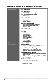
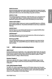
...-language BIOS ASUS TurboV utility Precision Tweaker 2 - ASUS Fanless Design: Heat-pipe solution - ASUS Q-Slot - ASUS EZ Flash 2 - ASUS MyLogo 2™ - ASUS TurboV ASUS Exclusive Features - vChipset(N.B.): 31-step chipset voltage control - ASUS Q-Shield - ASUS CrashFree BIOS 3 - vNB-PCIe: 65-step chipset-PCIe voltage control SFS (Stepless Frequency Selection) - P6X58D Premium specifications summary ASUS unique features ASUS exclusive overclocking features ASUS Xtreme Design ASUS Xtreme Phase: - ASUS Fan Xpert ASUS Crystal...
...-language BIOS ASUS TurboV utility Precision Tweaker 2 - ASUS Fanless Design: Heat-pipe solution - ASUS Q-Slot - ASUS EZ Flash 2 - ASUS MyLogo 2™ - ASUS TurboV ASUS Exclusive Features - vChipset(N.B.): 31-step chipset voltage control - ASUS Q-Shield - ASUS CrashFree BIOS 3 - vNB-PCIe: 65-step chipset-PCIe voltage control SFS (Stepless Frequency Selection) - P6X58D Premium specifications summary ASUS unique features ASUS exclusive overclocking features ASUS Xtreme Design ASUS Xtreme Phase: - ASUS Fan Xpert ASUS Crystal...
User Manual
Page 13
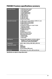
... Flash ROM, AMI BIOS, PnP, DMI 2.0, WfM 2.0, SM BIOS 2.3, ACPI 2.0a, Multi-language BIOS, ASUS EZ Flash 2, ASUS CrashFree BIOS 3 WfM 2.0, DMI 2.0, WOL by PME, WOR by PME, PXE Drivers ASUS Utilities ASUS Update Anti-virus software (OEM version) ATX form factor: 12 in 24-pin ATX Power connector 8-pin ATX 12V Power connector System Panel (Q-Connector) 1 x MemOK! P6X58D Premium specifications summary Back...
... Flash ROM, AMI BIOS, PnP, DMI 2.0, WfM 2.0, SM BIOS 2.3, ACPI 2.0a, Multi-language BIOS, ASUS EZ Flash 2, ASUS CrashFree BIOS 3 WfM 2.0, DMI 2.0, WOL by PME, WOR by PME, PXE Drivers ASUS Utilities ASUS Update Anti-virus software (OEM version) ATX form factor: 12 in 24-pin ATX Power connector 8-pin ATX 12V Power connector System Panel (Q-Connector) 1 x MemOK! P6X58D Premium specifications summary Back...
User Manual
Page 18
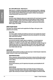
... even with easy ways to install computer components, update the BIOS, or back up your existing stereo speakers or headphones. Refer to different ambient temperatures caused by up and simplifies the DIY process! It effectively and noiselessly transfers heat generated by ASUS. making temperatures cooler by different climate conditions in variety of...
... even with easy ways to install computer components, update the BIOS, or back up your existing stereo speakers or headphones. Refer to different ambient temperatures caused by up and simplifies the DIY process! It effectively and noiselessly transfers heat generated by ASUS. making temperatures cooler by different climate conditions in variety of...
User Manual
Page 19
... utility that allows you to share and distribute your favorite settings. and its user-friendly interface makes overclock with the ASUS TurboV. Moreover, the ASUS OC profiles in different scenarios. ASUS P6X58D Premium 1-5 ASUS CrashFree BIOS 3 ASUS CrashFree BIOS 3 allows you to overclocking failure. This unique module eliminates the trouble of real-time OC-now a reality with just a few...
... utility that allows you to share and distribute your favorite settings. and its user-friendly interface makes overclock with the ASUS TurboV. Moreover, the ASUS OC profiles in different scenarios. ASUS P6X58D Premium 1-5 ASUS CrashFree BIOS 3 ASUS CrashFree BIOS 3 allows you to overclocking failure. This unique module eliminates the trouble of real-time OC-now a reality with just a few...

User Manual
Page 32
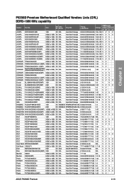
...(3 x 2GB) DS N/A Heat-Sink Package 8-8-8-24(1067-9-9-9-24) 1.65 V V P6X58D Premium Motherboard Qualified Vendors Lists (QVL) DDR3-1866 MHz capability Vendor Part No. Timing Lable(Bios) Voltage DIMM socket support (Optional) A* B* CORSAIR BoxP/N:TW3X4G1800C8DF (CM3X2G1800C8D)Ver4.1(XMP)...) 4GB(2 x 2GB) DS N/A Heat-Sink Package 7-7-7-21(1333-9-9-9-24) 1.65 V V P6X58D Premium Motherboard Qualified Vendors Lists (QVL) DDR3-1800 MHz capability Vendor Part No. Chapter 2 P6X58D Premium Motherboard Qualified Vendors Lists (QVL) DDR3-2000 MHz capability Vendor Part No.
...(3 x 2GB) DS N/A Heat-Sink Package 8-8-8-24(1067-9-9-9-24) 1.65 V V P6X58D Premium Motherboard Qualified Vendors Lists (QVL) DDR3-1866 MHz capability Vendor Part No. Timing Lable(Bios) Voltage DIMM socket support (Optional) A* B* CORSAIR BoxP/N:TW3X4G1800C8DF (CM3X2G1800C8D)Ver4.1(XMP)...) 4GB(2 x 2GB) DS N/A Heat-Sink Package 7-7-7-21(1333-9-9-9-24) 1.65 V V P6X58D Premium Motherboard Qualified Vendors Lists (QVL) DDR3-1800 MHz capability Vendor Part No. Chapter 2 P6X58D Premium Motherboard Qualified Vendors Lists (QVL) DDR3-2000 MHz capability Vendor Part No.
User Manual
Page 33
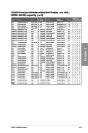
Size SS/ Chip DS Brand Chip NO. Timing Lable(Bios) DIMM socket Voltage support (Optional) A* B* C* D* A-DATA AD31600G001GMU 1GB SS N/A Heat-Sink Package 9-9-9-24 (1333-8-8-8-24) 1.65~1.85 V V V V A-DATA AX3U1600GB1G9-AG 2GB(2 x 1GB) SS N/A Heat-Sink ... 6GB(3 x 2GB) DS N/A Heat-Sink Package 9-9-9-24(1600-7-7-7-20) 1.65 VVV V Patriot PVT36G1600LLK(XMP) 6GB(3 x 2GB) DS N/A Heat-Sink Package 8-8-8-24(1067-7-7-7-20) 1.65 VV ASUS P6X58D Premium 2-13 Chapter 2 P6X58D Premium Motherboard Qualified Vendors Lists (QVL) DDR3-1600 MHz capability Vendor Part No.
Size SS/ Chip DS Brand Chip NO. Timing Lable(Bios) DIMM socket Voltage support (Optional) A* B* C* D* A-DATA AD31600G001GMU 1GB SS N/A Heat-Sink Package 9-9-9-24 (1333-8-8-8-24) 1.65~1.85 V V V V A-DATA AX3U1600GB1G9-AG 2GB(2 x 1GB) SS N/A Heat-Sink ... 6GB(3 x 2GB) DS N/A Heat-Sink Package 9-9-9-24(1600-7-7-7-20) 1.65 VVV V Patriot PVT36G1600LLK(XMP) 6GB(3 x 2GB) DS N/A Heat-Sink Package 8-8-8-24(1067-7-7-7-20) 1.65 VV ASUS P6X58D Premium 2-13 Chapter 2 P6X58D Premium Motherboard Qualified Vendors Lists (QVL) DDR3-1600 MHz capability Vendor Part No.
User Manual
Page 35
... Heat-Sink Package N/A Heat-Sink Package N/A Heat-Sink Package N/A Heat-Sink Package N/A Heat-Sink Package 1GB SS S-POWER I0YT3E0 2GB DS S-POWER I0YT3E0 Timing Lable(Bios) (1066-6-5-5) 9-9-9(1066-7-7-7-20) 7-7-7(1066-7-7-7-20) 8-8-8(1066-7-7-7-16) 9(1333-9-9-9-24) (1066-8-7-7-20) 9(1333-9-9-9-24) 9(1333-9-9-9-24) (1066-8-7-7-20) 9(1333-9-9-9-24) 9(1333-9-9-9-24) Voltage 1.85 1.65 1.... VVVV VVVV VVVV VVVV VVVV VVVV VVVV VVVV VVVV VVVV VVVV VV V VVVV VVVV VVVV VV V VVVV VV VVVV 9(1333-9-9-9-24) N/A VVVV 9(1333-9-9-9-24) N/A VVVV ASUS P6X58D Premium 2-15
... Heat-Sink Package N/A Heat-Sink Package N/A Heat-Sink Package N/A Heat-Sink Package N/A Heat-Sink Package 1GB SS S-POWER I0YT3E0 2GB DS S-POWER I0YT3E0 Timing Lable(Bios) (1066-6-5-5) 9-9-9(1066-7-7-7-20) 7-7-7(1066-7-7-7-20) 8-8-8(1066-7-7-7-16) 9(1333-9-9-9-24) (1066-8-7-7-20) 9(1333-9-9-9-24) 9(1333-9-9-9-24) (1066-8-7-7-20) 9(1333-9-9-9-24) 9(1333-9-9-9-24) Voltage 1.85 1.65 1.... VVVV VVVV VVVV VVVV VVVV VVVV VVVV VVVV VVVV VVVV VVVV VV V VVVV VVVV VVVV VV V VVVV VV VVVV 9(1333-9-9-9-24) N/A VVVV 9(1333-9-9-9-24) N/A VVVV ASUS P6X58D Premium 2-15
User Manual
Page 36
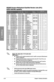
... MICRON D9KPT(ECC) SAMSUNG K4B2G0846B-HCF8 ELPIDA J1108BABG-AE-E Asint DDRIII1208-AE Asint DDRIII1208-AE N/A Heat-Sink Package Qimonda IDSH51-03A1F1C-10F Timing Lable(Bios) DIMM socket Voltage support (Optional) A* B* C* D* 7 1.1 VVV 7(1066-7-7-7-20) N/A V V V V 7 N/A V V V V 7(1066-9-9-9-25) N/A V V V V 7(1066-7-7-7-20) N/A V V V 7 N/A V V V V 7(1066-7-7-7-20) N/A V V 7(1066-7-7-7-20) N/A V V V V...ASUS exclusively provides hyper DIMM support function. • Hyper DIMM support is subject to the physical characteristics of individual CPUs. Chapter 2 P6X58D Premium...
... MICRON D9KPT(ECC) SAMSUNG K4B2G0846B-HCF8 ELPIDA J1108BABG-AE-E Asint DDRIII1208-AE Asint DDRIII1208-AE N/A Heat-Sink Package Qimonda IDSH51-03A1F1C-10F Timing Lable(Bios) DIMM socket Voltage support (Optional) A* B* C* D* 7 1.1 VVV 7(1066-7-7-7-20) N/A V V V V 7 N/A V V V V 7(1066-9-9-9-25) N/A V V V V 7(1066-7-7-7-20) N/A V V V 7 N/A V V V V 7(1066-7-7-7-20) N/A V V 7(1066-7-7-7-20) N/A V V V V...ASUS exclusively provides hyper DIMM support function. • Hyper DIMM support is subject to the physical characteristics of individual CPUs. Chapter 2 P6X58D Premium...
User Manual
Page 38
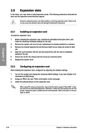
...After installing the expansion card, configure it and make the necessary hardware settings for information on the system and change the necessary BIOS settings, if any. Turn on BIOS setup. 2. Refer to the chassis with the screw you removed earlier. 6. Ensure to the card. Failure to do ...that they support. Assign an IRQ to unplug the power cord before adding or removing expansion cards. Otherwise, conflicts will arise between the two PCI groups, making the system unstable and the card inoperable. Refer to use . 4. Remove the system unit cover (if your motherboard is completely...
...After installing the expansion card, configure it and make the necessary hardware settings for information on the system and change the necessary BIOS settings, if any. Turn on BIOS setup. 2. Refer to the chassis with the screw you removed earlier. 6. Ensure to the card. Failure to do ...that they support. Assign an IRQ to unplug the power cord before adding or removing expansion cards. Otherwise, conflicts will arise between the two PCI groups, making the system unstable and the card inoperable. Refer to use . 4. Remove the system unit cover (if your motherboard is completely...
User Manual
Page 41
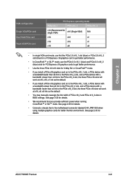
.../2/3 when using multiple graphics cards for better thermal environment. Chapter 2 VGA configuration Single VGA/PCIe card Dual VGA/PCIe card Triple VGA/PCIe card PCI Express operating mode PCIe x16_1 PCIe x16_2 PCIe x16_3 x16 (Recommend for single VGA) x16 (Single VGA) N/A x16 x16 x1 x16 x16... page 2-35 for details. • Connect a chassis fan to the PCIe x16_3 slot, the three PCIe x16 slots will work at x16, x16, x1 link as the default. • You may manually reassign the link width of PCIe x16_2 and PCIe x16_3 slots in BIOS settings. ASUS P6X58D Premium 2-21
.../2/3 when using multiple graphics cards for better thermal environment. Chapter 2 VGA configuration Single VGA/PCIe card Dual VGA/PCIe card Triple VGA/PCIe card PCI Express operating mode PCIe x16_1 PCIe x16_2 PCIe x16_3 x16 (Recommend for single VGA) x16 (Single VGA) N/A x16 x16 x1 x16 x16... page 2-35 for details. • Connect a chassis fan to the PCIe x16_3 slot, the three PCIe x16 slots will work at x16, x16, x1 link as the default. • You may manually reassign the link width of PCIe x16_2 and PCIe x16_3 slots in BIOS settings. ASUS P6X58D Premium 2-21
User Manual
Page 42
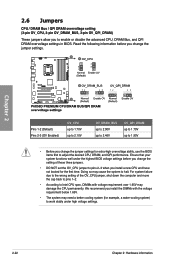
... the system to enable or disable the advanced CPU, DRAM Bus, and QPI DRAM overvoltage settings in BIOS. We recommend you install a new CPU and have not booted for extra-high overvoltage ability, use the BIOS items first to 1.90V • Before you change the setting of the OV_CPU jumper, shut down... to 2.46V OV_QPI_DRAM up to 1.70V up to adjust the desired CPU, DRAM, and QPI performance. Ensure that your system functions well under the highest BIOS voltage settings before you change the jumper settings for the first time.
... the system to enable or disable the advanced CPU, DRAM Bus, and QPI DRAM overvoltage settings in BIOS. We recommend you install a new CPU and have not booted for extra-high overvoltage ability, use the BIOS items first to 1.90V • Before you change the setting of the OV_CPU jumper, shut down... to 2.46V OV_QPI_DRAM up to 1.70V up to adjust the desired CPU, DRAM, and QPI performance. Ensure that your system functions well under the highest BIOS voltage settings before you change the jumper settings for the first time.

User Manual
Page 44
MemOK! switch Installing DIMMs that you download and update to the latest BIOS version from the ASUS website at www.asus.com. • If you turn off the computer and unplug the power cord for successful boot. Press and hold the MemOK! Turn off the computer ... the DIMM is tested. function. • Pressing the MemOK! switch under Windows® OS environment will appear during POST reminding you that the BIOS has been restored to BIOS overclocking, press the MemOK! A messgae will reboot the computer and start the memory tuning. • During the tuning process, the system loads and...
MemOK! switch Installing DIMMs that you download and update to the latest BIOS version from the ASUS website at www.asus.com. • If you turn off the computer and unplug the power cord for successful boot. Press and hold the MemOK! Turn off the computer ... the DIMM is tested. function. • Pressing the MemOK! switch under Windows® OS environment will appear during POST reminding you that the BIOS has been restored to BIOS overclocking, press the MemOK! A messgae will reboot the computer and start the memory tuning. • During the tuning process, the system loads and...
User Manual
Page 45
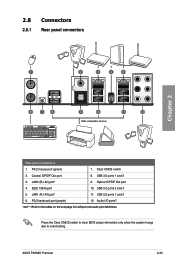
... 8. LAN2 (RJ-45) port* 9. LAN1 (RJ-45) port* 11. Press the Clear CMOS switch to clear BIOS setup information only when the system hangs due to the tables on the next page for LAN port and audio port definitions. 2.8 Connectors 2.8.1 Rear panel connectors Chapter 2 Rear panel connectors 1. ASUS P6X58D Premium 2-25 USB 2.0 ports 1 and 2 6.
... 8. LAN2 (RJ-45) port* 9. LAN1 (RJ-45) port* 11. Press the Clear CMOS switch to clear BIOS setup information only when the system hangs due to the tables on the next page for LAN port and audio port definitions. 2.8 Connectors 2.8.1 Rear panel connectors Chapter 2 Rear panel connectors 1. ASUS P6X58D Premium 2-25 USB 2.0 ports 1 and 2 6.
User Manual
Page 49
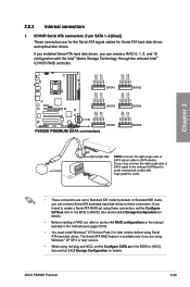
...® XP SP 2 or later version. • When using these connectors. If you are for the Serial ATA signal cables for details. ASUS P6X58D Premium 2-29 In Standard IDE mode, you can connect Serial ATA boot/data hard disk drives to [RAID]. The Serial ATA RAID feature is available ... intend to create a Serial ATA RAID set using hot-plug and NCQ, set the Configure SATA as in the BIOS to these connectors, set the Configure SATA as item in the BIOS to Standard IDE mode by default. See section 3.4.2 Storage Configuration for details. • Before creating a RAID set...
...® XP SP 2 or later version. • When using these connectors. If you are for the Serial ATA signal cables for details. ASUS P6X58D Premium 2-29 In Standard IDE mode, you can connect Serial ATA boot/data hard disk drives to [RAID]. The Serial ATA RAID feature is available ... intend to create a Serial ATA RAID set using hot-plug and NCQ, set the Configure SATA as in the BIOS to these connectors, set the Configure SATA as item in the BIOS to Standard IDE mode by default. See section 3.4.2 Storage Configuration for details. • Before creating a RAID set...
User Manual
Page 50
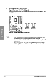
Refer to section 3.6.3 Onboard Devices Configuration for Serial ATA 6.0 Gb/s hard disk drives. • These connectors are set the Marvell 9123 Controller item in the BIOS to Standard IDE mode by default. 2. Marvell® Serial ATA 6.0 Gb/s connectors (7-pin SATA_6G_1, 7-pin SATA_6G_2 [gray]) These connectors are for the Serial ATA 6.0 Gb/s ...
Refer to section 3.6.3 Onboard Devices Configuration for Serial ATA 6.0 Gb/s hard disk drives. • These connectors are set the Marvell 9123 Controller item in the BIOS to Standard IDE mode by default. 2. Marvell® Serial ATA 6.0 Gb/s connectors (7-pin SATA_6G_1, 7-pin SATA_6G_2 [gray]) These connectors are for the Serial ATA 6.0 Gb/s ...
User Manual
Page 54
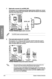
... connector, then install the module to [HD Audio]. 2-34 Chapter 2: Hardware information Chapter 2 The S/PDIF module is set the Front Panel Type item in the BIOS setup to [HD Audio];
... connector, then install the module to [HD Audio]. 2-34 Chapter 2: Hardware information Chapter 2 The S/PDIF module is set the Front Panel Type item in the BIOS setup to [HD Audio];

User Manual
Page 56
.... The system power LED lights up or flashes when data is for the chassis-mounted system warning speaker. The speaker allows you turn on the BIOS settings. Connect the chassis power LED cable to this connector. Connect the HDD Activity LED cable to this connector. 10. System panel connector (20-8 pin... chassis-mounted functions. Chapter 2 • System power LED (2-pin PLED) This 2-pin connector is read from or written to hear system beeps and warnings. • ATX power button/soft-off the system power. 2-36 Chapter 2: Hardware information
.... The system power LED lights up or flashes when data is for the chassis-mounted system warning speaker. The speaker allows you turn on the BIOS settings. Connect the chassis power LED cable to this connector. Connect the HDD Activity LED cable to this connector. 10. System panel connector (20-8 pin... chassis-mounted functions. Chapter 2 • System power LED (2-pin PLED) This 2-pin connector is read from or written to hear system beeps and warnings. • ATX power button/soft-off the system power. 2-36 Chapter 2: Hardware information


