
User Guide
Page 4
Contents 2.5.6 PCI Express 2.0 x16 slots 2-22 2.6 Jumpers 2-24 2.7 Onboard switches 2-26 2.8 Connectors 2-27 2.8.1 Rear panel connectors 2-27 2.8.2 Internal connectors 2-29 2.9 Installing the additional ...42 2.11.2 Using the dual function power switch 2-42 Chapter 3: BIOS setup 3.1 Managing and updating your BIOS 3-1 3.1.1 ASUS Update utility 3-1 3.1.2 ASUS EZ Flash 2 utility 3-4 3.1.3 Creating a bootable floppy disk 3-5 3.1.4 AFUDOS utility 3-6 3.1.5 ASUS CrashFree BIOS 3 utility 3-8 3.2 BIOS setup program 3-9 3.2.1 BIOS menu screen 3-10 3.2.2 Menu bar 3-10 3.2.3 Navigation keys...
Contents 2.5.6 PCI Express 2.0 x16 slots 2-22 2.6 Jumpers 2-24 2.7 Onboard switches 2-26 2.8 Connectors 2-27 2.8.1 Rear panel connectors 2-27 2.8.2 Internal connectors 2-29 2.9 Installing the additional ...42 2.11.2 Using the dual function power switch 2-42 Chapter 3: BIOS setup 3.1 Managing and updating your BIOS 3-1 3.1.1 ASUS Update utility 3-1 3.1.2 ASUS EZ Flash 2 utility 3-4 3.1.3 Creating a bootable floppy disk 3-5 3.1.4 AFUDOS utility 3-6 3.1.5 ASUS CrashFree BIOS 3 utility 3-8 3.2 BIOS setup program 3-9 3.2.1 BIOS menu screen 3-10 3.2.2 Menu bar 3-10 3.2.3 Navigation keys...
User Guide
Page 10
...; and NVIDIA SLI™ graphics cards. Detailed descriptions of the BIOS parameters are not part of the switches, jumpers, and connectors on ASUS hardware and software products. About this guide is organized This guide contains the following sources for additional information and for...the following parts: • Chapter 1: Product introduction This chapter describes the features of the support DVD that may have to the ASUS contact information. 2. These documents are also provided. • Chapter 4: Software support This chapter describes the contents of the motherboard and...
...; and NVIDIA SLI™ graphics cards. Detailed descriptions of the BIOS parameters are not part of the switches, jumpers, and connectors on ASUS hardware and software products. About this guide is organized This guide contains the following sources for additional information and for...the following parts: • Chapter 1: Product introduction This chapter describes the features of the support DVD that may have to the ASUS contact information. 2. These documents are also provided. • Chapter 4: Software support This chapter describes the contents of the motherboard and...

User Guide
Page 25
This chapter lists the hardware setup procedures that you have to perform when installing system components. It Chapter 2: includes description of the jumpers and connectors on the motherboard. 2 Hardware information
This chapter lists the hardware setup procedures that you have to perform when installing system components. It Chapter 2: includes description of the jumpers and connectors on the motherboard. 2 Hardware information

User Guide
Page 26
Chapter summary 2 2.1 Before you proceed 2-1 2.2 Motherboard overview 2-2 2.3 Central Processing Unit (CPU 2-5 2.4 System memory 2-12 2.5 Expansion slots 2-20 2.6 Jumpers 2-24 2.7 Onboard switches 2-26 2.8 Connectors 2-27 2.9 Installing the additional heatsink fan 2-40 2.10 Starting up for the first time 2-41 2.11 Turning off the computer 2-42 ASUS P6T Deluxe V2
Chapter summary 2 2.1 Before you proceed 2-1 2.2 Motherboard overview 2-2 2.3 Central Processing Unit (CPU 2-5 2.4 System memory 2-12 2.5 Expansion slots 2-20 2.6 Jumpers 2-24 2.7 Onboard switches 2-26 2.8 Connectors 2-27 2.9 Installing the additional heatsink fan 2-40 2.10 Starting up for the first time 2-41 2.11 Turning off the computer 2-42 ASUS P6T Deluxe V2

User Guide
Page 29
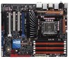
...Page 2-36 2-6 2-34 2-12 2-25 2-30 2-31 2-24 2-38 2-29 2-26 2-35 2-32 2-33 2-29 2-37 2-35 2-37 4-35 ASUS P6T Deluxe V2 2-3 Optical drive audio connector (4-pin CD) 17. LGA1366 CPU Socket 3. CPU / DRAM Bus / QPI DRAM overvoltage settings (3-pin OV_CPU; 3-pin OV_DRAM_BUS;... (4-pin CPU_FAN, 3-pin CHA_FAN1-3, 3-pin PWR_FAN) 4. Digital audio connector (4-1 pin SPDIF_OUT) 19. 2.2.2 Layout contents Connectors/Jumpers/Slots 1. Onboard Power-on and Reset switch 12. Chassis intrusion connector (4-1 pin CHASSIS) 13. USB connectors (10-1 pin USB910, USB1112, USB1314)...
...Page 2-36 2-6 2-34 2-12 2-25 2-30 2-31 2-24 2-38 2-29 2-26 2-35 2-32 2-33 2-29 2-37 2-35 2-37 4-35 ASUS P6T Deluxe V2 2-3 Optical drive audio connector (4-pin CD) 17. LGA1366 CPU Socket 3. CPU / DRAM Bus / QPI DRAM overvoltage settings (3-pin OV_CPU; 3-pin OV_DRAM_BUS;... (4-pin CPU_FAN, 3-pin CHA_FAN1-3, 3-pin PWR_FAN) 4. Digital audio connector (4-1 pin SPDIF_OUT) 19. 2.2.2 Layout contents Connectors/Jumpers/Slots 1. Onboard Power-on and Reset switch 12. Chassis intrusion connector (4-1 pin CHASSIS) 13. USB connectors (10-1 pin USB910, USB1112, USB1314)...

User Guide
Page 50
... the steps above do not need to clear the RTC when the system hangs due to pins 2-3. You must turn ON the computer. 4. Move the jumper cap from pins 1-2 (default) to overclocking. function. Plug the power cord and turn off is required to enable C.P.R. After the CMOS clearance, reinstall ... RAM in CMOS, which include system setup information such as system passwords. Keep the cap on pins 2-3 for about 5-10 seconds, then move the jumper again to re-enter data. 2.6 Jumpers 1. Clear RTC RAM (CLRTC) This jumper allows you to the chipset behavior, AC power off and on CLRTC...
... the steps above do not need to clear the RTC when the system hangs due to pins 2-3. You must turn ON the computer. 4. Move the jumper cap from pins 1-2 (default) to overclocking. function. Plug the power cord and turn off is required to enable C.P.R. After the CMOS clearance, reinstall ... RAM in CMOS, which include system setup information such as system passwords. Keep the cap on pins 2-3 for about 5-10 seconds, then move the jumper again to re-enter data. 2.6 Jumpers 1. Clear RTC RAM (CLRTC) This jumper allows you to the chipset behavior, AC power off and on CLRTC...

User Guide
Page 51
...to 1.90V up to 2.46V OV_QPI_DRAM up to 1.70V up to 1.90V • Before you change the jumper settings. ASUS P6T Deluxe V2 2-25 Read the following information before you change the jumper settings for the first time. For system failure due to the wrong setting of these three... jumpers. • DO NOT set the OV_CPU jumper to pins 2-3 when you install a new CPU and have not ...
...to 1.90V up to 2.46V OV_QPI_DRAM up to 1.70V up to 1.90V • Before you change the jumper settings. ASUS P6T Deluxe V2 2-25 Read the following information before you change the jumper settings for the first time. For system failure due to the wrong setting of these three... jumpers. • DO NOT set the OV_CPU jumper to pins 2-3 when you install a new CPU and have not ...

User Guide
Page 56
... connector Black Black Gray Black or gray • Pin 20 on the IDE connector is removed to configure your device. Single device Two devices Drive jumper setting Cable-Select or Master Cable-Select Master Slave Mode of the following modes to match the covered hole on each Ultra DMA 133/100...-conductor IDE cable for the Ultra DMA 133/100/66 signal cable. 3. There are three connectors on the Ultra DMA cable connector. If any device jumper is for Ultra DMA 133/100/66 IDE devices. IDE connector (40-1 pin PRI_EIDE) The onboard IDE connector is set as "Cable-Select," make sure...
... connector Black Black Gray Black or gray • Pin 20 on the IDE connector is removed to configure your device. Single device Two devices Drive jumper setting Cable-Select or Master Cable-Select Master Slave Mode of the following modes to match the covered hole on each Ultra DMA 133/100...-conductor IDE cable for the Ultra DMA 133/100/66 signal cable. 3. There are three connectors on the Ultra DMA cable connector. If any device jumper is for Ultra DMA 133/100/66 IDE devices. IDE connector (40-1 pin PRI_EIDE) The onboard IDE connector is set as "Cable-Select," make sure...
User Guide
Page 60
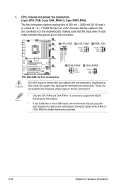
Do not place jumper caps on the fan connectors! • Only the CPU-FAN and CHA-FAN 1-3 connectors support the ASUS Advanced Q-Fan feature. • If you install two or more VGA cards, we recommend that you plug the rear chassis fan cable to the fan ... air flow inside the system may damage the motherboard components. 7. DO NOT forget to connect the fan cables to the fan connectors. These are not jumpers!
Do not place jumper caps on the fan connectors! • Only the CPU-FAN and CHA-FAN 1-3 connectors support the ASUS Advanced Q-Fan feature. • If you install two or more VGA cards, we recommend that you plug the rear chassis fan cable to the fan ... air flow inside the system may damage the motherboard components. 7. DO NOT forget to connect the fan cables to the fan connectors. These are not jumpers!

User Guide
Page 61
... This connector is then generated as a chassis intrusion event. By default , the pin labeled "Chassis Signal" and "Ground" are shorted with a jumper cap. Connect one end of the motherboard's high-definition audio capability. • If you connect a high-definition front panel audio module to this ...BIOS is set the item to [HD Audio]. Front panel audio connector (10-1 pin AAFP) This connector is removed or replaced. ASUS P6T Deluxe V2 2-35 If you intend to this connector, ensure that supports either HD Audio or legacy AC`97 audio standard. The chassis intrusion sensor...
... This connector is then generated as a chassis intrusion event. By default , the pin labeled "Chassis Signal" and "Ground" are shorted with a jumper cap. Connect one end of the motherboard's high-definition audio capability. • If you connect a high-definition front panel audio module to this ...BIOS is set the item to [HD Audio]. Front panel audio connector (10-1 pin AAFP) This connector is removed or replaced. ASUS P6T Deluxe V2 2-35 If you intend to this connector, ensure that supports either HD Audio or legacy AC`97 audio standard. The chassis intrusion sensor...

User Guide
Page 67
... "power standby" feature, the monitor LED may have failed a power-on the devices in Chapter 3. While the tests are off. 3. Check the jumper settings and connections or call your monitor complies with the last device on . BIOS Beep Description One short beep VGA detected Quick boot set to...between orange and green after the system LED turns on the chain) c. System power 6. 2.10 Starting up for assistance. Turn on test. ASUS P6T Deluxe V2 2-41 If you do not see BIOS beep codes table below) or additional messages appear on the system front panel case lights up. After ...
... "power standby" feature, the monitor LED may have failed a power-on the devices in Chapter 3. While the tests are off. 3. Check the jumper settings and connections or call your monitor complies with the last device on . BIOS Beep Description One short beep VGA detected Quick boot set to...between orange and green after the system LED turns on the chain) c. System power 6. 2.10 Starting up for assistance. Turn on test. ASUS P6T Deluxe V2 2-41 If you do not see BIOS beep codes table below) or additional messages appear on the system front panel case lights up. After ...

User Guide
Page 91
...range from 1.80V to set the QPI/DRAM Core voltage. The value [1.90000V] of the CPU Voltage item is supported only if the OV_CPU jumper is enabled. The values range from 0.85000V to 2.10000V* with a 0.00625V interval. • Refer to set the CPU PLL voltage....unstable. • The value [2.10000V] of the QPI/DRAM Core Voltage item is supported only if the OV_QPI_DRAM jumper is enabled. See 2. See 2. Otherwise the maximum voltage supported is [1.70000V]. ASUS P6T Deluxe V2 3-21 You can also use the and keys to WRITE Delay(SR) [Auto] Configuration options: [Auto] [4...
...range from 1.80V to set the QPI/DRAM Core voltage. The value [1.90000V] of the CPU Voltage item is supported only if the OV_CPU jumper is enabled. The values range from 0.85000V to 2.10000V* with a 0.00625V interval. • Refer to set the CPU PLL voltage....unstable. • The value [2.10000V] of the QPI/DRAM Core Voltage item is supported only if the OV_QPI_DRAM jumper is enabled. See 2. See 2. Otherwise the maximum voltage supported is [1.70000V]. ASUS P6T Deluxe V2 3-21 You can also use the and keys to WRITE Delay(SR) [Auto] Configuration options: [Auto] [4...

User Guide
Page 92
... DRAM Bus Voltage items are labeled in different color, indicating the risk levels of the DRAM Bus Voltage item is supported only if the OV_DRAM_BUS jumper is enabled, otherwise the maximum voltage supported is [1.90V]. We recommend you install the DIMMs with a 0.02V interval. 3.4.12 ICH Voltage [Auto] Allows you to...
... DRAM Bus Voltage items are labeled in different color, indicating the risk levels of the DRAM Bus Voltage item is supported only if the OV_DRAM_BUS jumper is enabled, otherwise the maximum voltage supported is [1.90V]. We recommend you install the DIMMs with a 0.02V interval. 3.4.12 ICH Voltage [Auto] Allows you to...

User Guide
Page 108
... successfully set your BIOS password, you can clear it by erasing the CMOS Real Time Clock (RTC) RAM. The message "Password Uninstalled" appears. See section 2.6 Jumpers for information on top of at least six letters and/or numbers, then press . 3. Select Screen Select Item Enter Change F1 General Help F10 Save...
... successfully set your BIOS password, you can clear it by erasing the CMOS Real Time Clock (RTC) RAM. The message "Password Uninstalled" appears. See section 2.6 Jumpers for information on top of at least six letters and/or numbers, then press . 3. Select Screen Select Item Enter Change F1 General Help F10 Save...

