
Motherboard Installation Guide
Page 17
... , check the items in the long line of the above items is damaged or missing, contact your retailer. ASUS P5W64 WS Professional 1-1 Thank you start installing the motherboard, and hardware devices on it another standout in your package with the... package for the following items. Motherboard I /O shield ASUS motherboard support CD InterVideo® Media Launcher User guide If any of ASUS quality motherboards! 1.1 Welcome! Before you for up to 7 devices I /O modules Cables Accessories Application CD Documentation ASUS P5W64 WS PRO motherboard 1 x 2-port IEEE 1394a module 1 ...
... , check the items in the long line of the above items is damaged or missing, contact your retailer. ASUS P5W64 WS Professional 1-1 Thank you start installing the motherboard, and hardware devices on it another standout in your package with the... package for the following items. Motherboard I /O shield ASUS motherboard support CD InterVideo® Media Launcher User guide If any of ASUS quality motherboards! 1.1 Welcome! Before you for up to 7 devices I /O modules Cables Accessories Application CD Documentation ASUS P5W64 WS PRO motherboard 1 x 2-port IEEE 1394a module 1 ...
Motherboard Installation Guide
Page 19
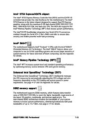
... SpeedStep® Technology (EIST) The Enhanced Intel SpeedStep® Technology (EIST) intelligently manages the CPU resources by optimizing memory access between CPU and system memory. ASUS P5W64 WS Professional 1-3 The Intel® 975X Express is the latest chipset designed to support Dual PCI Express graphics, along with the Intel® EM64T (Extended Memory...
... SpeedStep® Technology (EIST) The Enhanced Intel SpeedStep® Technology (EIST) intelligently manages the CPU resources by optimizing memory access between CPU and system memory. ASUS P5W64 WS Professional 1-3 The Intel® 975X Express is the latest chipset designed to support Dual PCI Express graphics, along with the Intel® EM64T (Extended Memory...
Motherboard Installation Guide
Page 21
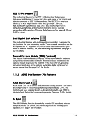
... design on to systems and enable digital signatures for secure transactions.See page 2-43 for details. 1.3.2 ASUS Intelligence (AI) features ASUS Stack Cool 2 ASUS Stack Cool 2 is a secure microcontroller hardware component with dual Gigabit LAN controllers to provide faster data bandwidth... requirements. These network controllers use the PCI Express and PCI segments to provide the total solution for your networking needs. ASUS P5W64 WS Professional 1-5 See page 2-3 for details. Dual Gigabit LAN solution The motherboard comes with embedded software. See page 232 ...
... design on to systems and enable digital signatures for secure transactions.See page 2-43 for details. 1.3.2 ASUS Intelligence (AI) features ASUS Stack Cool 2 ASUS Stack Cool 2 is a secure microcontroller hardware component with dual Gigabit LAN controllers to provide faster data bandwidth... requirements. These network controllers use the PCI Express and PCI segments to provide the total solution for your networking needs. ASUS P5W64 WS Professional 1-5 See page 2-3 for details. Dual Gigabit LAN solution The motherboard comes with embedded software. See page 232 ...
Motherboard Installation Guide
Page 23
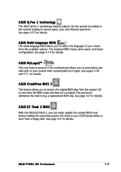
... need to restore the original BIOS data from the available options. See page 4-14 for details. See page 4-9 for details. ASUS P5W64 WS Professional 1-7 The localized BIOS menus allow easier and faster configuration. ASUS Q-Fan 2 technology The ASUS Q-Fan 2 technology smartly adjusts the fan speeds according to the system loading to buy a replacement ROM chip...
... need to restore the original BIOS data from the available options. See page 4-14 for details. See page 4-9 for details. ASUS P5W64 WS Professional 1-7 The localized BIOS menus allow easier and faster configuration. ASUS Q-Fan 2 technology The ASUS Q-Fan 2 technology smartly adjusts the fan speeds according to the system loading to buy a replacement ROM chip...
Motherboard Installation Guide
Page 26
Chapter summary 2 2.1 Before you proceed 2-1 2.2 Motherboard overview 2-2 2.3 Central Processing Unit (CPU 2-7 2.4 System memory 2-14 2.5 Expansion slots 2-20 2.6 Jumpers 2-27 2.7 Connectors 2-28 ASUS P5W64 WS Professional
Chapter summary 2 2.1 Before you proceed 2-1 2.2 Motherboard overview 2-2 2.3 Central Processing Unit (CPU 2-7 2.4 System memory 2-14 2.5 Expansion slots 2-20 2.6 Jumpers 2-27 2.7 Connectors 2-28 ASUS P5W64 WS Professional
Motherboard Installation Guide
Page 27
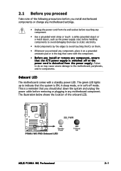
2.1 Before you proceed Take note of the onboard LED. ® P5W64 WS PRO SB_PWR ON Standby Power P5W64 WS PRO Onboard LED OFF Powered Off ASUS P5W64 WS Professional 2-1 The green LED lights up to indicate that you should shut down the system and unplug the power cable before handling components to avoid ...
2.1 Before you proceed Take note of the onboard LED. ® P5W64 WS PRO SB_PWR ON Standby Power P5W64 WS PRO Onboard LED OFF Powered Off ASUS P5W64 WS Professional 2-1 The green LED lights up to indicate that you should shut down the system and unplug the power cable before handling components to avoid ...
Motherboard Installation Guide
Page 29
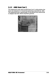
The motherboard uses a special design on the printed circuit board (PCB) to dissipate heat that lowers the temperature of critical heat generating components by 20ºC. 2.2.3 ASUS Stack Cool 2 The motherboard comes with the ASUS Stack Cool 2 cooling solution that critical components generate. ASUS P5W64 WS Professional 2-3
The motherboard uses a special design on the printed circuit board (PCB) to dissipate heat that lowers the temperature of critical heat generating components by 20ºC. 2.2.3 ASUS Stack Cool 2 The motherboard comes with the ASUS Stack Cool 2 cooling solution that critical components generate. ASUS P5W64 WS Professional 2-3
Motherboard Installation Guide
Page 33
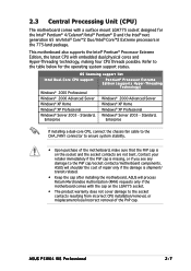
...with a surface mount LGA775 socket designed for the operating system support status. Standard, Windows® Server 2003 - ASUS will shoulder the cost of repair only if the damage is shipment/ transit-related. • Keep the cap after...® D and the Intel® next generation 65 nm/Intel® Core™2 Duo/Intel® Core™2 Extreme processors in the 775-land package. ASUS P5W64 WS Professional 2-7 Refer to the PnP cap/socket contacts/motherboard components. OS licensing support list Intel Dual-Core CPU support P e n t i u m® P r o c e s s o r E x t r e ...
...with a surface mount LGA775 socket designed for the operating system support status. Standard, Windows® Server 2003 - ASUS will shoulder the cost of repair only if the damage is shipment/ transit-related. • Keep the cap after...® D and the Intel® next generation 65 nm/Intel® Core™2 Duo/Intel® Core™2 Extreme processors in the 775-land package. ASUS P5W64 WS Professional 2-7 Refer to the PnP cap/socket contacts/motherboard components. OS licensing support list Intel Dual-Core CPU support P e n t i u m® P r o c e s s o r E x t r e ...

Motherboard Installation Guide
Page 35
... information on the bottom-left corner of the socket. Close the load plate (A), then A push the load lever (B) until it snaps into the CPU notch. ASUS P5W64 WS Professional 2-9 4. The socket alignment A l i g n m e n t k e y key should fit into the retention tab. If installing a dual-core CPU, connect the chassis fan cable to the CHA_FAN1 connector...
... information on the bottom-left corner of the socket. Close the load plate (A), then A push the load lever (B) until it snaps into the CPU notch. ASUS P5W64 WS Professional 2-9 4. The socket alignment A l i g n m e n t k e y key should fit into the retention tab. If installing a dual-core CPU, connect the chassis fan cable to the CHA_FAN1 connector...

Motherboard Installation Guide
Page 37
A B A B A B B A 3. Hardware monitoring errors can occur if you fail to the connector on the motherboard labeled CPU_FAN. ASUS P5W64 WS Professional 2-11 Connect the CPU fan cable to plug this connector. Push down two fasteners at a time in place. CPU_FAN ® P5W64 WS PRO CPU FAN PWM CPU FAN IN CPU FAN PWR GND P5W64 WS PRO CPU fan connector Do not forget to secure the heatsink and fan assembly in a diagonal sequence to connect the CPU fan connector! 2.
A B A B A B B A 3. Hardware monitoring errors can occur if you fail to the connector on the motherboard labeled CPU_FAN. ASUS P5W64 WS Professional 2-11 Connect the CPU fan cable to plug this connector. Push down two fasteners at a time in place. CPU_FAN ® P5W64 WS PRO CPU FAN PWM CPU FAN IN CPU FAN PWR GND P5W64 WS PRO CPU fan connector Do not forget to secure the heatsink and fan assembly in a diagonal sequence to connect the CPU fan connector! 2.
Motherboard Installation Guide
Page 39
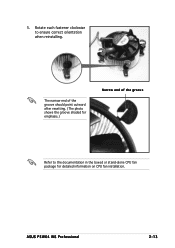
ASUS P5W64 WS Professional 2-13 5. Rotate each fastener clockwise to the documentation in the boxed or stand-alone CPU fan package for emphasis.) Narrow end of the groove Refer to ensure correct orientation when reinstalling. The narrow end of the groove should point outward after resetting. (The photo shows the groove shaded for detailed information on CPU fan installation.
ASUS P5W64 WS Professional 2-13 5. Rotate each fastener clockwise to the documentation in the boxed or stand-alone CPU fan package for emphasis.) Narrow end of the groove Refer to ensure correct orientation when reinstalling. The narrow end of the groove should point outward after resetting. (The photo shows the groove shaded for detailed information on CPU fan installation.
Motherboard Installation Guide
Page 41
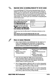
...DDR2-533 2 GB density modules are available for third party comments on this issue: http://dlsvr01.asus.com/pub/ASUS/mb/4GB_Rev1.pdf http://www.intel.com/support/motherboards/server/sb/cs-016594.htm Notes on memory ...® XP 32-bit version OS. You may install a maximum of memory space for further explanation: http://support.asus.com/faq/ faq.aspx?SLanguage=en-us Under G e n e r a l s e a r c h, make the selections as shown, then click S e a r c h. ASUS P5W64 WS Professional 2-15 I m p o r t a n t n o t i c e o n i n s t a l l i n g W i n d o w s® X P 3 2 - b i t v e r s i...
...DDR2-533 2 GB density modules are available for third party comments on this issue: http://dlsvr01.asus.com/pub/ASUS/mb/4GB_Rev1.pdf http://www.intel.com/support/motherboards/server/sb/cs-016594.htm Notes on memory ...® XP 32-bit version OS. You may install a maximum of memory space for further explanation: http://support.asus.com/faq/ faq.aspx?SLanguage=en-us Under G e n e r a l s e a r c h, make the selections as shown, then click S e a r c h. ASUS P5W64 WS Professional 2-15 I m p o r t a n t n o t i c e o n i n s t a l l i n g W i n d o w s® X P 3 2 - b i t v e r s i...
Motherboard Installation Guide
Page 43
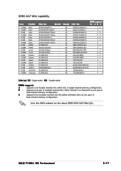
HY5PS12821AFP-Y4(ECC) - E5108AE-6E-E - AD29608A8B-3EG - Visit the ASUS website for the latest DDR2-800/667 MHz QVL. HY5PS1G831FP-Y5(ECC) - HY5PS12821AFP-Y5(ECC) - E5108AE-6E-E - Side(s) Part No. Single-sided D S - Double-...Kingmax Apacer Apacer A-DATA A-DATA Transcend Transcend Chip No. Heat-Sink Package - E5108AE-6E-E - E5108AE-6E-E - B - C - ASUS P5W64 WS Professional 2-17 E5108AE-6E-E - Supports one pair of Dual-channel memory configuration. Supports one pair of Dual-channel memory configuration. HY5PS12821AFP-Y4 ...
HY5PS12821AFP-Y4(ECC) - E5108AE-6E-E - AD29608A8B-3EG - Visit the ASUS website for the latest DDR2-800/667 MHz QVL. HY5PS1G831FP-Y5(ECC) - HY5PS12821AFP-Y5(ECC) - E5108AE-6E-E - Side(s) Part No. Single-sided D S - Double-...Kingmax Apacer Apacer A-DATA A-DATA Transcend Transcend Chip No. Heat-Sink Package - E5108AE-6E-E - E5108AE-6E-E - B - C - ASUS P5W64 WS Professional 2-17 E5108AE-6E-E - Supports one pair of Dual-channel memory configuration. Supports one pair of Dual-channel memory configuration. HY5PS12821AFP-Y4 ...
Motherboard Installation Guide
Page 45
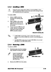
... on the socket such that it flips out with your fingers when pressing the retaining clips. Remove the DIMM from the socket. 2 1 DDR2 DIMM notch ASUS P5W64 WS Professional 2-19 Unlock a DIMM socket by pressing the retaining clips outward. 2. Do not force a DIMM into the socket until the retaining clips snap back in...
... on the socket such that it flips out with your fingers when pressing the retaining clips. Remove the DIMM from the socket. 2 1 DDR2 DIMM notch ASUS P5W64 WS Professional 2-19 Unlock a DIMM socket by pressing the retaining clips outward. 2. Do not force a DIMM into the socket until the retaining clips snap back in...
Motherboard Installation Guide
Page 47
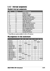
... Serial ATA HD Audio A B C D E F G H - - - - - shared - - - - shared - - shared - - - shared - - --- shared shared shared - shared - shared - - - - shared - - - - - IRQ assignments for ISA or PCI devices. shared - - - - - - - - shared - - - - shared shared ASUS P5W64 WS Professional 2-21 shared - - - - - - - - shared - - - - - - - - shared - - - - - - - - shared - -
... Serial ATA HD Audio A B C D E F G H - - - - - shared - - - - shared - - shared - - - shared - - --- shared shared shared - shared - shared - - - - shared - - - - - IRQ assignments for ISA or PCI devices. shared - - - - - - - - shared - - - - shared shared ASUS P5W64 WS Professional 2-21 shared - - - - - - - - shared - - - - - - - - shared - - - - - - - - shared - -
Motherboard Installation Guide
Page 49
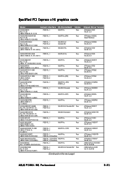
...Radeon X300 V8.231.0.0 ATI Radeon X300SE (Hyper Memory) ATI Radeon X300SE V8.252.0.0 ATI Radeon X550 V8.241.0.0 ASUS EAX550GE 256M (BIOS: V5B60.8.15.139. Pass ATI Radeon X550 V8.252.0.0 ASUS EAX600XT PCIEX16_1 WinXP Pro. Pass (BIOS: V5E4D.9.7.1.3. PN: 109-A47401-10 (BIOS: V009.007.001.004) PCIEX16_1 ... ATI Radeon X1900XTX V8.241.0.0 ATI Radeon X1900CF V8.241.0.0 nVIDIA GeForce PCX5900 V6.14.10.8198 nVIDIA GeForce 6200 V6.14.10.8198 ASUS P5W64 WS Professional 2-23 A901) ASUS EAX700-X 128M PCIEX16_1 WinXP Pro. V1.00 (BIOS: V5549.9.4.1.10.AS) PCIEX16_1 Win2003 Standard Pass...
...Radeon X300 V8.231.0.0 ATI Radeon X300SE (Hyper Memory) ATI Radeon X300SE V8.252.0.0 ATI Radeon X550 V8.241.0.0 ASUS EAX550GE 256M (BIOS: V5B60.8.15.139. Pass ATI Radeon X550 V8.252.0.0 ASUS EAX600XT PCIEX16_1 WinXP Pro. Pass (BIOS: V5E4D.9.7.1.3. PN: 109-A47401-10 (BIOS: V009.007.001.004) PCIEX16_1 ... ATI Radeon X1900XTX V8.241.0.0 ATI Radeon X1900CF V8.241.0.0 nVIDIA GeForce PCX5900 V6.14.10.8198 nVIDIA GeForce 6200 V6.14.10.8198 ASUS P5W64 WS Professional 2-23 A901) ASUS EAX700-X 128M PCIEX16_1 WinXP Pro. V1.00 (BIOS: V5549.9.4.1.10.AS) PCIEX16_1 Win2003 Standard Pass...
Motherboard Installation Guide
Page 53
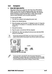
...in CMOS. Plug the power cord and turn ON the computer. 6. Removing the cap will cause system boot failure! ® P5W64 WS PRO CLRTC 12 23 Normal (Default) P5W64 WS PRO Clear RTC RAM Clear RTC You do not need to clear the RTC when the system hangs due to re-enter...from pins 1-2 (default) to default values. Shut down the key during the boot process and enter BIOS setup to overclocking. Remove the onboard battery. 3. ASUS P5W64 WS Professional 2-27 2.6 Jumpers 1. Clear RTC RAM (CLRTC) This jumper allows you to clear the Real Time Clock (RTC) RAM in CMOS, which include system...
...in CMOS. Plug the power cord and turn ON the computer. 6. Removing the cap will cause system boot failure! ® P5W64 WS PRO CLRTC 12 23 Normal (Default) P5W64 WS PRO Clear RTC RAM Clear RTC You do not need to clear the RTC when the system hangs due to re-enter...from pins 1-2 (default) to default values. Shut down the key during the boot process and enter BIOS setup to overclocking. Remove the onboard battery. 3. ASUS P5W64 WS Professional 2-27 2.6 Jumpers 1. Clear RTC RAM (CLRTC) This jumper allows you to clear the Real Time Clock (RTC) RAM in CMOS, which include system...
Motherboard Installation Guide
Page 55
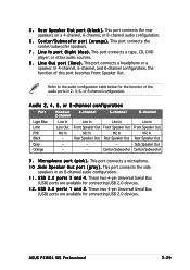
... Front Speaker Out Mic In Mic In Mic In Mic In - These two 4-pin Universal Serial Bus (USB) ports are available for connecting USB 2.0 devices. L i n e O u t p o r t ( l i m e ) . ASUS P5W64 WS Professional 2-29 This port connects a tape, CD, DVD player, or other audio sources. 8 . U S B 2 . 0 p o r t s 1 a n d 2 . Side Speaker Out - - R e a r S p e a k e r O u t p o r t ( b l a c k ) . This port connects a microphone...
... Front Speaker Out Mic In Mic In Mic In Mic In - These two 4-pin Universal Serial Bus (USB) ports are available for connecting USB 2.0 devices. L i n e O u t p o r t ( l i m e ) . ASUS P5W64 WS Professional 2-29 This port connects a tape, CD, DVD player, or other audio sources. 8 . U S B 2 . 0 p o r t s 1 a n d 2 . Side Speaker Out - - R e a r S p e a k e r O u t p o r t ( b l a c k ) . This port connects a microphone...

Motherboard Installation Guide
Page 57
...black, and gray. There are three connectors on the floppy ribbon cable to PIN 1. Pin 5 on the Ultra DMA cable connector. P5W64 WS PRO IDE connector • Pin 20 on the IDE connector is removed to match the covered hole on the connector is removed to PIN... zigzag) on the IDE ribbon cable to prevent incorrect cable connection when using a FDD cable with a covered Pin 5. ASUS P5W64 WS Professional 2-31 ® P5W64 WS PRO 2.7.2 Internal connectors 1 . PIN 1 P5W64 WS PRO Floppy disk drive connector 2 . Insert one of the floppy disk drive. Floppy disk drive connector (34-1 pin ...
...black, and gray. There are three connectors on the floppy ribbon cable to PIN 1. Pin 5 on the Ultra DMA cable connector. P5W64 WS PRO IDE connector • Pin 20 on the IDE connector is removed to match the covered hole on the connector is removed to PIN... zigzag) on the IDE ribbon cable to prevent incorrect cable connection when using a FDD cable with a covered Pin 5. ASUS P5W64 WS Professional 2-31 ® P5W64 WS PRO 2.7.2 Internal connectors 1 . PIN 1 P5W64 WS PRO Floppy disk drive connector 2 . Insert one of the floppy disk drive. Floppy disk drive connector (34-1 pin ...
Motherboard Installation Guide
Page 59
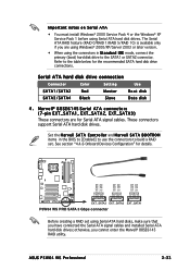
... have connected the Serial ATA signal cables and installed Serial ATA hard disk drives; otherwise, you are for the recommended SATA hard disk drive connections. ASUS P5W64 WS Professional 2-33 Set the M a r v e l l S A T A C o n t r o l l e r and M a r v e l l S A T A B O O T R O M items in S t a n d a r d I ... Serial ATA hard disk drives. See section "4.4.6 Onboard Devices Configuration" for details. ® P5W64 WS PRO GND RSATA_TX_0_DP RSATA_TX_0_DN GND RSATA_RX_0_DN RSATA_RX_0_DP GND GND RSATA_TX_1_DP RSATA_TX_1_DN GND RSATA_RX_1_DN RSATA_RX_1_DP GND GND RSATA_TX_2_DP...
... have connected the Serial ATA signal cables and installed Serial ATA hard disk drives; otherwise, you are for the recommended SATA hard disk drive connections. ASUS P5W64 WS Professional 2-33 Set the M a r v e l l S A T A C o n t r o l l e r and M a r v e l l S A T A B O O T R O M items in S t a n d a r d I ... Serial ATA hard disk drives. See section "4.4.6 Onboard Devices Configuration" for details. ® P5W64 WS PRO GND RSATA_TX_0_DP RSATA_TX_0_DN GND RSATA_RX_0_DN RSATA_RX_0_DP GND GND RSATA_TX_1_DP RSATA_TX_1_DN GND RSATA_RX_1_DN RSATA_RX_1_DP GND GND RSATA_TX_2_DP...


