
Motherboard Installation Guide
Page 17
... the following items. Motherboard I/O modules Cables Accessories Application CD Documentation ASUS P5W64 WS PRO motherboard 1 x 2-port IEEE 1394a module 1 x 2-port USB 2.0 module 1 x Floppy disk drive cable 1 x Ultra DMA 133/100/66 cable 7 x Serial ATA signal cables 4 x Serial ATA power cables for buying an ASUS® P5W64 WS Professional Workstation motherboard! Thank you start installing the motherboard, and hardware...
... the following items. Motherboard I/O modules Cables Accessories Application CD Documentation ASUS P5W64 WS PRO motherboard 1 x 2-port IEEE 1394a module 1 x 2-port USB 2.0 module 1 x Floppy disk drive cable 1 x Ultra DMA 133/100/66 cable 7 x Serial ATA signal cables 4 x Serial ATA power cables for buying an ASUS® P5W64 WS Professional Workstation motherboard! Thank you start installing the motherboard, and hardware...
Motherboard Installation Guide
Page 27
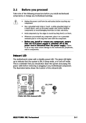
... up to indicate that the system is switched off mode. 2.1 Before you proceed Take note of the onboard LED. ® P5W64 WS PRO SB_PWR ON Standby Power P5W64 WS PRO Onboard LED OFF Powered Off ASUS P5W64 WS Professional 2-1 This is a reminder that you should shut down the system and unplug the power cable before handling components to avoid damaging...
... up to indicate that the system is switched off mode. 2.1 Before you proceed Take note of the onboard LED. ® P5W64 WS PRO SB_PWR ON Standby Power P5W64 WS PRO Onboard LED OFF Powered Off ASUS P5W64 WS Professional 2-1 This is a reminder that you should shut down the system and unplug the power cable before handling components to avoid damaging...

Motherboard Installation Guide
Page 37
2. Connect the CPU fan cable to connect the CPU fan connector! CPU_FAN ® P5W64 WS PRO CPU FAN PWM CPU FAN IN CPU FAN PWR GND P5W64 WS PRO CPU fan connector Do not forget to the connector on the motherboard labeled CPU_FAN. ASUS P5W64 WS Professional 2-11 Hardware monitoring errors can occur if you fail to secure the heatsink and fan assembly in a diagonal sequence to plug this connector. A B A B A B B A 3. Push down two fasteners at a time in place.
2. Connect the CPU fan cable to connect the CPU fan connector! CPU_FAN ® P5W64 WS PRO CPU FAN PWM CPU FAN IN CPU FAN PWR GND P5W64 WS PRO CPU fan connector Do not forget to the connector on the motherboard labeled CPU_FAN. ASUS P5W64 WS Professional 2-11 Hardware monitoring errors can occur if you fail to secure the heatsink and fan assembly in a diagonal sequence to plug this connector. A B A B A B B A 3. Push down two fasteners at a time in place.
Motherboard Installation Guide
Page 49
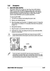
... GeForce 6200 V6.14.10.8198 ASUS P5W64 WS Professional 2-23 Pass (BIOS: V5D4F.9.7. 1.4.AS02) ASUS EAX850XT 256MB Rev. Pass (BIOS: 7249.9.12.5.2AS05) PCIEX16_2 (CrossFire) ASUS EN5900 PCIEX16_1 WinXP Pro. WinXP Pro.(JPN) Win2003-64 Standard R2 Win2000 Pro. Pass ATI Radeon X550 V8.252.0.0 ASUS EAX600XT PCIEX16_1 WinXP Pro. AS01) PCIEX16_1 WinXP-64 Pro. Pass (BIOS: V5E4D.9.7.1.3. Pass (BIOS: V009...
... GeForce 6200 V6.14.10.8198 ASUS P5W64 WS Professional 2-23 Pass (BIOS: V5D4F.9.7. 1.4.AS02) ASUS EAX850XT 256MB Rev. Pass (BIOS: 7249.9.12.5.2AS05) PCIEX16_2 (CrossFire) ASUS EN5900 PCIEX16_1 WinXP Pro. WinXP Pro.(JPN) Win2003-64 Standard R2 Win2000 Pro. Pass ATI Radeon X550 V8.252.0.0 ASUS EAX600XT PCIEX16_1 WinXP Pro. AS01) PCIEX16_1 WinXP-64 Pro. Pass (BIOS: V5E4D.9.7.1.3. Pass (BIOS: V009...
Motherboard Installation Guide
Page 53
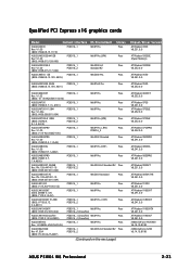
.... Turn OFF the computer and unplug the power cord. 2. Keep the cap on CLRTC jumper default position. ASUS P5W64 WS Professional 2-27 Removing the cap will cause system boot failure! ® P5W64 WS PRO CLRTC 12 23 Normal (Default) P5W64 WS PRO Clear RTC RAM Clear RTC You do not need to clear the RTC when the system hangs due...
.... Turn OFF the computer and unplug the power cord. 2. Keep the cap on CLRTC jumper default position. ASUS P5W64 WS Professional 2-27 Removing the cap will cause system boot failure! ® P5W64 WS PRO CLRTC 12 23 Normal (Default) P5W64 WS PRO Clear RTC RAM Clear RTC You do not need to clear the RTC when the system hangs due...

Motherboard Installation Guide
Page 57
...removed to the signal connector at the back of the floppy disk drive. ® P5W64 WS PRO 2.7.2 Internal connectors 1 . There are three connectors on the Ultra DMA cable connector. ASUS P5W64 WS Professional 2-31 P5W64 WS PRO IDE connector • Pin 20 on the IDE ribbon cable to PIN 1. Floppy disk... blue connector to the motherboard's IDE connector, then select one end of the following modes to configure your device. ® P5W64 WS PRO PRI_IDE NOTE: Orient the red markings (usually zigzag) on the IDE connector is removed to PIN 1. This prevents incorrect insertion when...
...removed to the signal connector at the back of the floppy disk drive. ® P5W64 WS PRO 2.7.2 Internal connectors 1 . There are three connectors on the Ultra DMA cable connector. ASUS P5W64 WS Professional 2-31 P5W64 WS PRO IDE connector • Pin 20 on the IDE ribbon cable to PIN 1. Floppy disk... blue connector to the motherboard's IDE connector, then select one end of the following modes to configure your device. ® P5W64 WS PRO PRI_IDE NOTE: Orient the red markings (usually zigzag) on the IDE connector is removed to PIN 1. This prevents incorrect insertion when...
Motherboard Installation Guide
Page 59
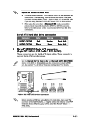
... disk drive connection Connector Color Setting Use SATA1/SATA2 Red Master Boot disk SATA3/SATA4 Black Slave Data disk 4 . ASUS P5W64 WS Professional 2-33 The Serial ATA RAID feature (RAID 0/RAID 1/RAID 5/RAID 10) is available only if you are for ... the connectors in the BIOS to [Enabled] to use the connectors to the table below for details. ® P5W64 WS PRO GND RSATA_TX_0_DP RSATA_TX_0_DN GND RSATA_RX_0_DN RSATA_RX_0_DP GND GND RSATA_TX_1_DP RSATA_TX_1_DN GND RSATA_RX_1_DN RSATA_RX_1_DP GND GND RSATA_TX_2_DP RSATA_TX_2_DN GND RSATA_RX_2_DN RSATA_RX_2_DP GND EXT_SATA3...
... disk drive connection Connector Color Setting Use SATA1/SATA2 Red Master Boot disk SATA3/SATA4 Black Slave Data disk 4 . ASUS P5W64 WS Professional 2-33 The Serial ATA RAID feature (RAID 0/RAID 1/RAID 5/RAID 10) is available only if you are for ... the connectors in the BIOS to [Enabled] to use the connectors to the table below for details. ® P5W64 WS PRO GND RSATA_TX_0_DP RSATA_TX_0_DN GND RSATA_RX_0_DN RSATA_RX_0_DP GND GND RSATA_TX_1_DP RSATA_TX_1_DN GND RSATA_RX_1_DN RSATA_RX_1_DP GND GND RSATA_TX_2_DP RSATA_TX_2_DN GND RSATA_RX_2_DN RSATA_RX_2_DP GND EXT_SATA3...
Motherboard Installation Guide
Page 61
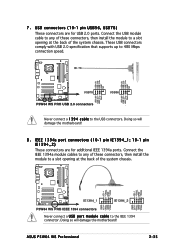
...the system chassis. ® P5W64 WS PRO TPA2+ GND TPB2+ +12V TPA1+ GND TPB1+ +12V TPA2GND TPB2+12V GND IE1394_1 IE1394_2 TPA1GND TPB1+12V GND P5W64 WS PRO IEEE 1394 connectors Never connect a U S B p o r t m o d u l e c a b l e to the USB connectors. ASUS P5W64 WS Professional 2-35 USB connectors (10... comply with USB 2.0 specification that supports up to 480 Mbps connection speed. ® P5W64 WS PRO USB+5V USB_P6USB_P6+ GND NC USB+5V USB_P8USB_P8+ GND NC USB+5V USB_P5USB_P5+ GND USB78 P5W64 WS PRO USB 2.0 connectors USB+5V USB_P7USB_P7+ GND USB56 Never connect a 1 3 9 4 ...
...the system chassis. ® P5W64 WS PRO TPA2+ GND TPB2+ +12V TPA1+ GND TPB1+ +12V TPA2GND TPB2+12V GND IE1394_1 IE1394_2 TPA1GND TPB1+12V GND P5W64 WS PRO IEEE 1394 connectors Never connect a U S B p o r t m o d u l e c a b l e to the USB connectors. ASUS P5W64 WS Professional 2-35 USB connectors (10... comply with USB 2.0 specification that supports up to 480 Mbps connection speed. ® P5W64 WS PRO USB+5V USB_P6USB_P6+ GND NC USB+5V USB_P8USB_P8+ GND NC USB+5V USB_P5USB_P5+ GND USB78 P5W64 WS PRO USB 2.0 connectors USB+5V USB_P7USB_P7+ GND USB56 Never connect a 1 3 9 4 ...
Motherboard Installation Guide
Page 63
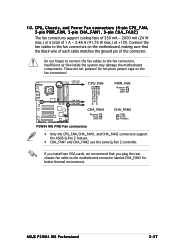
10. Insufficient air flow inside the system may damage the motherboard components. ASUS P5W64 WS Professional 2-37 These are not jumpers! Do not place jumper caps on the motherboard, making sure that you plug the rear chassis fan cable to the ... FAN PWM CPU FAN IN CPU FAN PWR GND CHA_FAN1 CHA_FAN2 CHA_FAN1 Rotation +12V GND CHA_FAN2 GND +12V Rotation P5W64 WS PRO Fan connectors • Only the CPU_FAN, CHA_FAN1, and CHA_FAN2 connectors support the ASUS Q-Fan 2 feature. • CHA_FAN1 and CHA_FAN2 use the same Q-Fan 2 controller. If you install two VGA cards, we ...
10. Insufficient air flow inside the system may damage the motherboard components. ASUS P5W64 WS Professional 2-37 These are not jumpers! Do not place jumper caps on the motherboard, making sure that you plug the rear chassis fan cable to the ... FAN PWM CPU FAN IN CPU FAN PWR GND CHA_FAN1 CHA_FAN2 CHA_FAN1 Rotation +12V GND CHA_FAN2 GND +12V Rotation P5W64 WS PRO Fan connectors • Only the CPU_FAN, CHA_FAN1, and CHA_FAN2 connectors support the ASUS Q-Fan 2 feature. • CHA_FAN1 and CHA_FAN2 use the same Q-Fan 2 controller. If you install two VGA cards, we ...

Motherboard Installation Guide
Page 67
... system power button. PWR Ground Reset Ground 14. Connect the HDD Activity LED cable to this connector. PLED+ PLED+5V Ground Ground Speaker ® P5W64 WS PRO IDE_LED+ IDE_LED- P5W64 WS PRO System panel connector • System power LED This 3-pin connector is for the HDD Activity LED. Pressing the power button turns the system on... This 4-pin connector is for system reboot without turning off button This connector is for the chassis-mounted reset button for the system power LED. ASUS P5W64 WS Professional 2-41
... system power button. PWR Ground Reset Ground 14. Connect the HDD Activity LED cable to this connector. PLED+ PLED+5V Ground Ground Speaker ® P5W64 WS PRO IDE_LED+ IDE_LED- P5W64 WS PRO System panel connector • System power LED This 3-pin connector is for the HDD Activity LED. Pressing the power button turns the system on... This 4-pin connector is for system reboot without turning off button This connector is for the chassis-mounted reset button for the system power LED. ASUS P5W64 WS Professional 2-41
Motherboard Installation Guide
Page 79
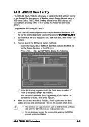
ASUSTek EZ Flash 2 BIOS ROM Utility V3.00 FLASH TYPE: Winbond W39V080A 8Mb LPC Current ROM BOARD: P5W64-WS Pro VER: 0204 DATE: 07/04/2006 Update ROM BOARD: Unknown VER: Unknown DATE: Unknown PATH: A:\ A: Note [Enter] Select [Tab] Switch [S] Save [ESC]Exit ... accessible by two methods. (1) Insert the floppy disk / USB flash disk that contains the BIOS file to the floppy disk drive or the USB port. ASUS P5W64 WS Professional 4-5 To update the BIOS using a DOS-based utility. Save the BIOS file to W 6 4 W S P R O . Press + during the Power-On Self Tests (POST). The EZ Flash...
ASUSTek EZ Flash 2 BIOS ROM Utility V3.00 FLASH TYPE: Winbond W39V080A 8Mb LPC Current ROM BOARD: P5W64-WS Pro VER: 0204 DATE: 07/04/2006 Update ROM BOARD: Unknown VER: Unknown DATE: Unknown PATH: A:\ A: Note [Enter] Select [Tab] Switch [S] Save [ESC]Exit ... accessible by two methods. (1) Insert the floppy disk / USB flash disk that contains the BIOS file to the floppy disk drive or the USB port. ASUS P5W64 WS Professional 4-5 To update the BIOS using a DOS-based utility. Save the BIOS file to W 6 4 W S P R O . Press + during the Power-On Self Tests (POST). The EZ Flash...
Motherboard Installation Guide
Page 119
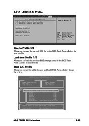
...Profile 2 Load from Profile 1/2 Allows you to load the previous BIOS settings saved in the BIOS Flash. Press to save the file. 4.7.2 ASUS O.C. Load from Profile 2 Start O.C. Profile Allows you to the BIOS Flash. Profile Main Advanced BIOS SETUP UTILITY Power Boot Tools O.C. PROFILE ...:00 Note [Enter] Select or Load [B] Backup [ESC] Exit [Tab] Switch [Up/Down/Home/End] Move ASUS P5W64 WS Professional 4-45 Profile Utility V1.00 Current CMOS BOARD: P5W64-WS PRO VER: 0116 DATE: 08/01/06 Update CMOS BOARD: Unknown VER: Unknown DATE: Unknown PATH: C:\ A: CMOS ...
...Profile 2 Load from Profile 1/2 Allows you to load the previous BIOS settings saved in the BIOS Flash. Press to save the file. 4.7.2 ASUS O.C. Load from Profile 2 Start O.C. Profile Allows you to the BIOS Flash. Profile Main Advanced BIOS SETUP UTILITY Power Boot Tools O.C. PROFILE ...:00 Note [Enter] Select or Load [B] Backup [ESC] Exit [Tab] Switch [Up/Down/Home/End] Move ASUS P5W64 WS Professional 4-45 Profile Utility V1.00 Current CMOS BOARD: P5W64-WS PRO VER: 0116 DATE: 08/01/06 Update CMOS BOARD: Unknown VER: Unknown DATE: Unknown PATH: C:\ A: CMOS ...

Motherboard Installation Guide
Page 163
... menu appears. 1) Intel ICH7R RAID/AHCI Driver Page 2) Marvell 88SE6141 SATA Driver for P5WDG2 WS PRO Page 3) Marvell 88SE6145 SATA RAID Driver for drive B:\ and press ENTER when ready... 7. Press to continue. The following message displays on screen. ASUS P5W64 WS Professional 5-39 Press any key when prompted to boot from CDROM... You can create a RAID...
... menu appears. 1) Intel ICH7R RAID/AHCI Driver Page 2) Marvell 88SE6141 SATA Driver for P5WDG2 WS PRO Page 3) Marvell 88SE6145 SATA RAID Driver for drive B:\ and press ENTER when ready... 7. Press to continue. The following message displays on screen. ASUS P5W64 WS Professional 5-39 Press any key when prompted to boot from CDROM... You can create a RAID...


