
Motherboard Installation Guide
Page 1
Motherboard P5W64 WS Professional
Motherboard P5W64 WS Professional

Motherboard Installation Guide
Page 3
... vii Safety information viii About this guide ix P5W64 WS Professional specifications summary xi Chapter 1: Product introduction 1.1 Welcome 1-1 1.2 Package contents 1-1 1.3 Special features 1-2 1.3.1 Product highlights 1-2 1.3.2 ASUS Intelligence (AI) features 1-5 1.3.3 Innovative ASUS features 1-6 Chapter 2: Hardware information 2.1 Before you proceed 2-1 2.2 Motherboard overview 2-2 2.2.1 Placement direction 2-2 2.2.2 Screw holes 2-2 2.2.3 ASUS Stack Cool 2 2-3 2.2.4 Motherboard layout 2-4 2.2.5 Layout contents 2-5 2.3 Central Processing Unit (CPU 2-7 2.3.1 Installing...
... vii Safety information viii About this guide ix P5W64 WS Professional specifications summary xi Chapter 1: Product introduction 1.1 Welcome 1-1 1.2 Package contents 1-1 1.3 Special features 1-2 1.3.1 Product highlights 1-2 1.3.2 ASUS Intelligence (AI) features 1-5 1.3.3 Innovative ASUS features 1-6 Chapter 2: Hardware information 2.1 Before you proceed 2-1 2.2 Motherboard overview 2-2 2.2.1 Placement direction 2-2 2.2.2 Screw holes 2-2 2.2.3 ASUS Stack Cool 2 2-3 2.2.4 Motherboard layout 2-4 2.2.5 Layout contents 2-5 2.3 Central Processing Unit (CPU 2-7 2.3.1 Installing...

Motherboard Installation Guide
Page 8
...a qualified service technician or your dealer immediately. • To avoid short circuits, keep paper clips, screws, and staples away from the motherboard, ensure that your retailer. Safety information Electrical safety • To prevent electrical shock hazard, disconnect the power cable from the electrical outlet ...by yourself. Please check local regulations for the devices are unplugged before the signal cables are unplugged. • Seek professional assistance before you encounter technical problems with the package. • Before using an adpater or extension cord.
...a qualified service technician or your dealer immediately. • To avoid short circuits, keep paper clips, screws, and staples away from the motherboard, ensure that your retailer. Safety information Electrical safety • To prevent electrical shock hazard, disconnect the power cable from the electrical outlet ...by yourself. Please check local regulations for the devices are unplugged before the signal cables are unplugged. • Seek professional assistance before you encounter technical problems with the package. • Before using an adpater or extension cord.

Motherboard Installation Guide
Page 17
... with the list below. 1.2 Package contents Check your motherboard package for the following items. Motherboard I/O modules Cables Accessories Application CD Documentation ASUS P5W64 WS PRO motherboard 1 x 2-port IEEE 1394a module 1 x 2-port USB 2.0 module 1 x Floppy disk drive cable 1 x Ultra DMA 133/100/66 cable 7 x Serial ATA signal cables 4 x Serial ATA power cables for buying an ASUS® P5W64 WS Professional Workstation motherboard!
... with the list below. 1.2 Package contents Check your motherboard package for the following items. Motherboard I/O modules Cables Accessories Application CD Documentation ASUS P5W64 WS PRO motherboard 1 x 2-port IEEE 1394a module 1 x 2-port USB 2.0 module 1 x Floppy disk drive cable 1 x Ultra DMA 133/100/66 cable 7 x Serial ATA signal cables 4 x Serial ATA power cables for buying an ASUS® P5W64 WS Professional Workstation motherboard!
Motherboard Installation Guide
Page 19
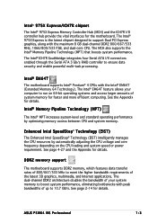
...doubles the bandwidth of your computer to run on the CPU loading and system speed or power requirement. Intel® EM64T The motherboard supports Intel® Pentium® 4 CPUs with the maximum 8 GB dual-channel DDR2 800/667/533 MHz, 1066/800/... manages the CPU resources by optimizing memory access between CPU and system memory. ASUS P5W64 WS Professional 1-3 The Intel® ICH7R Southbridge integrates four Serial ATA I /O controller hub provide the vital interfaces for the motherboard. The Intel® EM64T feature allows your system memory to boost system performance...
...doubles the bandwidth of your computer to run on the CPU loading and system speed or power requirement. Intel® EM64T The motherboard supports Intel® Pentium® 4 CPUs with the maximum 8 GB dual-channel DDR2 800/667/533 MHz, 1066/800/... manages the CPU resources by optimizing memory access between CPU and system memory. ASUS P5W64 WS Professional 1-3 The Intel® ICH7R Southbridge integrates four Serial ATA I /O controller hub provide the vital interfaces for the motherboard. The Intel® EM64T feature allows your system memory to boost system performance...
Motherboard Installation Guide
Page 21
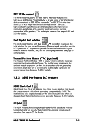
... and zero-noise cooling solution that lowers the temperature of peripherals and devices compliant to IEEE 1394a standards. Dual Gigabit LAN solution The motherboard comes with embedded software. ASUS P5W64 WS Professional 1-5 See page 2-3 for details. See pages 2-33 and 2-38 for details. See page 4-35 for details. These network controllers use the PCI Express...
... and zero-noise cooling solution that lowers the temperature of peripherals and devices compliant to IEEE 1394a standards. Dual Gigabit LAN solution The motherboard comes with embedded software. ASUS P5W64 WS Professional 1-5 See page 2-3 for details. See pages 2-33 and 2-38 for details. See page 4-35 for details. These network controllers use the PCI Express...
Motherboard Installation Guide
Page 23
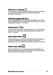
... options. See pages 4-38 and 5-11 for details. ASUS EZ Flash 2 BIOS With the ASUS EZ Flash 2, you to your choice from the support CD in the motherboard allows you to use a DOS-based utility or boot from a floppy disk. ASUS P5W64 WS Professional 1-7 See page 4-14 for details. ASUS MyLogo2™ This new feature present in case...
... options. See pages 4-38 and 5-11 for details. ASUS EZ Flash 2 BIOS With the ASUS EZ Flash 2, you to your choice from the support CD in the motherboard allows you to use a DOS-based utility or boot from a floppy disk. ASUS P5W64 WS Professional 1-7 See page 4-14 for details. ASUS MyLogo2™ This new feature present in case...
Motherboard Installation Guide
Page 26
Chapter summary 2 2.1 Before you proceed 2-1 2.2 Motherboard overview 2-2 2.3 Central Processing Unit (CPU 2-7 2.4 System memory 2-14 2.5 Expansion slots 2-20 2.6 Jumpers 2-27 2.7 Connectors 2-28 ASUS P5W64 WS Professional
Chapter summary 2 2.1 Before you proceed 2-1 2.2 Motherboard overview 2-2 2.3 Central Processing Unit (CPU 2-7 2.4 System memory 2-14 2.5 Expansion slots 2-20 2.6 Jumpers 2-27 2.7 Connectors 2-28 ASUS P5W64 WS Professional
Motherboard Installation Guide
Page 27
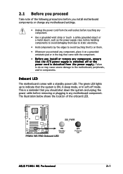
...power LED. The illustration below shows the location of the following precautions before you install motherboard components or change any motherboard settings. • Unplug the power cord from the wall socket before touching any component... d e t a c h e d f r o m t h e p o w e r s u p p l y . This is switched off mode. 2.1 Before you proceed Take note of the onboard LED. ® P5W64 WS PRO SB_PWR ON Standby Power P5W64 WS PRO Onboard LED OFF Powered Off ASUS P5W64 WS Professional 2-1 Failure to do so may cause severe damage to the motherboard, peripherals, and/or components.
...power LED. The illustration below shows the location of the following precautions before you install motherboard components or change any motherboard settings. • Unplug the power cord from the wall socket before touching any component... d e t a c h e d f r o m t h e p o w e r s u p p l y . This is switched off mode. 2.1 Before you proceed Take note of the onboard LED. ® P5W64 WS PRO SB_PWR ON Standby Power P5W64 WS PRO Onboard LED OFF Powered Off ASUS P5W64 WS Professional 2-1 Failure to do so may cause severe damage to the motherboard, peripherals, and/or components.
Motherboard Installation Guide
Page 29
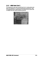
The motherboard uses a special design on the printed circuit board (PCB) to dissipate heat that lowers the temperature of critical heat generating components by 20ºC. ASUS P5W64 WS Professional 2-3 2.2.3 ASUS Stack Cool 2 The motherboard comes with the ASUS Stack Cool 2 cooling solution that critical components generate.
The motherboard uses a special design on the printed circuit board (PCB) to dissipate heat that lowers the temperature of critical heat generating components by 20ºC. ASUS P5W64 WS Professional 2-3 2.2.3 ASUS Stack Cool 2 The motherboard comes with the ASUS Stack Cool 2 cooling solution that critical components generate.
Motherboard Installation Guide
Page 33
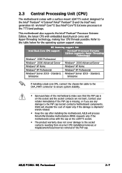
...XP Home Windows® XP Home Windows® XP Professional Windows® XP Professional Windows® Server 2003 - Standard, Windows® Server 2003 - ASUS will process Return Merchandise Authorization (RMA) requests only if the motherboard comes with the cap on the LGA775 socket. •...; Core™2 Duo/Intel® Core™2 Extreme processors in the 775-land package. ASUS will shoulder the cost of the PnP cap. ASUS P5W64 WS Professional 2-7 This motherboard also supports the Intel® Pentium® Processor Extreme Edition, the latest CPU with embedded dual...
...XP Home Windows® XP Home Windows® XP Professional Windows® XP Professional Windows® Server 2003 - Standard, Windows® Server 2003 - ASUS will process Return Merchandise Authorization (RMA) requests only if the motherboard comes with the cap on the LGA775 socket. •...; Core™2 Duo/Intel® Core™2 Extreme processors in the 775-land package. ASUS will shoulder the cost of the PnP cap. ASUS P5W64 WS Professional 2-7 This motherboard also supports the Intel® Pentium® Processor Extreme Edition, the latest CPU with embedded dual...

Motherboard Installation Guide
Page 35
..., making sure that the gold triangle is on the socket and damaging the CPU! 6. ASUS P5W64 WS Professional 2-9 Refer to ensure system stability. B 7. Close the load plate (A), then A push the load lever (B) until it snaps into the retention tab. The motherboard supports Intel® Pentium® 4 LGA775 processors with your thumb and forefinger to a 100...
..., making sure that the gold triangle is on the socket and damaging the CPU! 6. ASUS P5W64 WS Professional 2-9 Refer to ensure system stability. B 7. Close the load plate (A), then A push the load lever (B) until it snaps into the retention tab. The motherboard supports Intel® Pentium® 4 LGA775 processors with your thumb and forefinger to a 100...

Motherboard Installation Guide
Page 37
Connect the CPU fan cable to connect the CPU fan connector! ASUS P5W64 WS Professional 2-11 2. CPU_FAN ® P5W64 WS PRO CPU FAN PWM CPU FAN IN CPU FAN PWR GND P5W64 WS PRO CPU fan connector Do not forget to the connector on the motherboard labeled CPU_FAN. Hardware monitoring errors can occur if you fail to secure the heatsink and fan assembly in place. Push down two fasteners at a time in a diagonal sequence to plug this connector. A B A B A B B A 3.
Connect the CPU fan cable to connect the CPU fan connector! ASUS P5W64 WS Professional 2-11 2. CPU_FAN ® P5W64 WS PRO CPU FAN PWM CPU FAN IN CPU FAN PWR GND P5W64 WS PRO CPU fan connector Do not forget to the connector on the motherboard labeled CPU_FAN. Hardware monitoring errors can occur if you fail to secure the heatsink and fan assembly in place. Push down two fasteners at a time in a diagonal sequence to plug this connector. A B A B A B B A 3.
Motherboard Installation Guide
Page 41
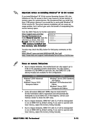
...listed below for third party comments on this issue: http://dlsvr01.asus.com/pub/ASUS/mb/4GB_Rev1.pdf http://www.intel.com/support/motherboards/server/sb/cs-016594.htm Notes on memory limitations • Due to chipset limitation, this motherboard can only support up to 8 GB on each slot, ... less than 3 GB system memory if you want to operate with CL=3 will automatically downgrade to run at DDR2-533 by default setting. ASUS P5W64 WS Professional 2-15 If you install Windows® XP 32-bit version Operating System (OS), the limitation of this configuration. 32-bit Windows® ...
...listed below for third party comments on this issue: http://dlsvr01.asus.com/pub/ASUS/mb/4GB_Rev1.pdf http://www.intel.com/support/motherboards/server/sb/cs-016594.htm Notes on memory limitations • Due to chipset limitation, this motherboard can only support up to 8 GB on each slot, ... less than 3 GB system memory if you want to operate with CL=3 will automatically downgrade to run at DDR2-533 by default setting. ASUS P5W64 WS Professional 2-15 If you install Windows® XP 32-bit version Operating System (OS), the limitation of this configuration. 32-bit Windows® ...
Motherboard Installation Guide
Page 45
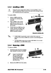
... only one direction. Remove the DIMM from the socket. 2 1 DDR2 DIMM notch ASUS P5W64 WS Professional 2-19 Firmly insert the DIMM into a socket to avoid damaging the DIMM. • The DDR2 DIMM sockets do so can cause severe damage to both the motherboard and the components. Simultaneously press the retaining clips outward to the DDR2...
... only one direction. Remove the DIMM from the socket. 2 1 DDR2 DIMM notch ASUS P5W64 WS Professional 2-19 Firmly insert the DIMM into a socket to avoid damaging the DIMM. • The DDR2 DIMM sockets do so can cause severe damage to both the motherboard and the components. Simultaneously press the retaining clips outward to the DDR2...
Motherboard Installation Guide
Page 47
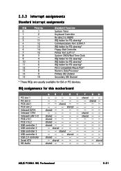
...- shared - - --- shared - - shared - - - - IRQ assignments for ISA or PCI devices. shared - - - - shared - - - - - - - - shared - - - - - shared shared shared - shared shared ASUS P5W64 WS Professional 2-21 shared - - - - - - - - shared - - - - shared - shared - - shared - - - - - - - - 2.5.3 Interrupt assignments Standard interrupt assignments IRQ Priority 0 1 1 2 2 - 3 11 ... IDE Channel Secondary IDE Channel * These IRQs are usually available for this motherboard PCI slot 1 PCI slot 2 PCIX slot 1 PCIX slot 2 Onboard ...
...- shared - - --- shared - - shared - - - - IRQ assignments for ISA or PCI devices. shared - - - - shared - - - - - - - - shared - - - - - shared shared shared - shared shared ASUS P5W64 WS Professional 2-21 shared - - - - - - - - shared - - - - shared - shared - - shared - - - - - - - - 2.5.3 Interrupt assignments Standard interrupt assignments IRQ Priority 0 1 1 2 2 - 3 11 ... IDE Channel Secondary IDE Channel * These IRQs are usually available for this motherboard PCI slot 1 PCI slot 2 PCIX slot 1 PCIX slot 2 Onboard ...

Motherboard Installation Guide
Page 57
...ribbon cable to PIN 1. Pin 5 on the floppy ribbon cable to prevent incorrect cable connection when using a FDD cable with a covered Pin 5. ASUS P5W64 WS Professional 2-31 FLOPPY NOTE: Orient the red markings on the connector is for Ultra DMA 100/66 IDE devices. This prevents incorrect insertion when you connect... other end to match the covered hole on each Ultra DMA 133/100/66 signal cable: blue, black, and gray. ® P5W64 WS PRO 2.7.2 Internal connectors 1 . Connect the blue connector to the motherboard's IDE connector, then select one end of the floppy disk drive.
...ribbon cable to PIN 1. Pin 5 on the floppy ribbon cable to prevent incorrect cable connection when using a FDD cable with a covered Pin 5. ASUS P5W64 WS Professional 2-31 FLOPPY NOTE: Orient the red markings on the connector is for Ultra DMA 100/66 IDE devices. This prevents incorrect insertion when you connect... other end to match the covered hole on each Ultra DMA 133/100/66 signal cable: blue, black, and gray. ® P5W64 WS PRO 2.7.2 Internal connectors 1 . Connect the blue connector to the motherboard's IDE connector, then select one end of the floppy disk drive.
Motherboard Installation Guide
Page 61
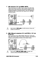
Doing so will damage the motherboard! ASUS P5W64 WS Professional 2-35 Connect the USB module cable to any of these connectors, then install the module to the USB connectors. Doing so will damage the motherboard! 8 . These USB connectors comply with USB 2.0 specification that supports up to 480 Mbps connection speed. ® P5W64 WS PRO USB+5V USB_P6USB_P6+ GND NC...
Doing so will damage the motherboard! ASUS P5W64 WS Professional 2-35 Connect the USB module cable to any of these connectors, then install the module to the USB connectors. Doing so will damage the motherboard! 8 . These USB connectors comply with USB 2.0 specification that supports up to 480 Mbps connection speed. ® P5W64 WS PRO USB+5V USB_P6USB_P6+ GND NC...
Motherboard Installation Guide
Page 63
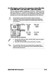
...ASUS P5W64 WS Professional 2-37 If you install two VGA cards, we recommend that the black wire of each cable matches the ground pin of 1 A ~ 3.48 A (41.76 W max.) at +12V. Connect the fan cables to the fan connectors on the fan connectors! Insufficient air flow inside the system may damage the motherboard...CHA_FAN2 GND +12V Rotation P5W64 WS PRO Fan connectors • Only the CPU_FAN, CHA_FAN1, and CHA_FAN2 connectors support the ASUS Q-Fan 2 feature. • CHA_FAN1 and CHA_FAN2 use the same Q-Fan 2 controller. Do not place jumper caps on the motherboard, making sure that you ...
...ASUS P5W64 WS Professional 2-37 If you install two VGA cards, we recommend that the black wire of each cable matches the ground pin of 1 A ~ 3.48 A (41.76 W max.) at +12V. Connect the fan cables to the fan connectors on the fan connectors! Insufficient air flow inside the system may damage the motherboard...CHA_FAN2 GND +12V Rotation P5W64 WS PRO Fan connectors • Only the CPU_FAN, CHA_FAN1, and CHA_FAN2 connectors support the ASUS Q-Fan 2 feature. • CHA_FAN1 and CHA_FAN2 use the same Q-Fan 2 controller. Do not place jumper caps on the motherboard, making sure that you ...

Motherboard Installation Guide
Page 65
... ATX power supply unit; ASUS P5W64 WS Professional 2-39 otherwise, the system will not boot up if the power is recommended when configuring a system with more power consuming devices. The system may become unstable or may not boot up . • You can support at least DC 16A (peak 22A) on motherboard power requirements • For...
... ATX power supply unit; ASUS P5W64 WS Professional 2-39 otherwise, the system will not boot up if the power is recommended when configuring a system with more power consuming devices. The system may become unstable or may not boot up . • You can support at least DC 16A (peak 22A) on motherboard power requirements • For...


