
Motherboard Installation Guide
Page 13
This chapter describes the motherboard features and the new technologies it supports. 1Product introduction ASUS P5RD2-VM 1-1
This chapter describes the motherboard features and the new technologies it supports. 1Product introduction ASUS P5RD2-VM 1-1

Motherboard Installation Guide
Page 14
... Pentium® 4 or Intel® Pentium® D processor with RAID functionality. Before you for the following items. Motherboard ASUS P5RD2-VM motherboard Cables 1 x 2-in the 775-land package. The motherboard also supports the Intel® Hyper-Threading Technology and is ...cable 2 x Serial ATA signal cables 1 x Serial ATA power cables Accessories I/O shield Application CDs ASUS motherboard support CD Documentation User guide If any of ASUS quality motherboards! SATA RAID solution Onboard RAID controllers provide the motherboard with 800/533 MHz Front Side Bus...
... Pentium® 4 or Intel® Pentium® D processor with RAID functionality. Before you for the following items. Motherboard ASUS P5RD2-VM motherboard Cables 1 x 2-in the 775-land package. The motherboard also supports the Intel® Hyper-Threading Technology and is ...cable 2 x Serial ATA signal cables 1 x Serial ATA power cables Accessories I/O shield Application CDs ASUS motherboard support CD Documentation User guide If any of ASUS quality motherboards! SATA RAID solution Onboard RAID controllers provide the motherboard with 800/533 MHz Front Side Bus...

Motherboard Installation Guide
Page 15
... devices and allows higher clockspeeds by automatically adjusting the CPU voltage and core frequency depending on the CPU loading and system speed or power requirement. ASUS P5RD2-VM 1-3 Enhanced Intel SpeedStep® Technology (EIST) The Enhanced Intel SpeedStep® Technology (EIST) intelligently manages the CPU resources by carrying data in the 775-land...
... devices and allows higher clockspeeds by automatically adjusting the CPU voltage and core frequency depending on the CPU loading and system speed or power requirement. ASUS P5RD2-VM 1-3 Enhanced Intel SpeedStep® Technology (EIST) The Enhanced Intel SpeedStep® Technology (EIST) intelligently manages the CPU resources by carrying data in the 775-land...

Motherboard Installation Guide
Page 17
... may cause severe damage to indicate that the system is a reminder that the ATX power supply is switched off mode. P5RD2-VM ® P5RD2-VM Onboard LED SB_PWR ON Standby Power OFF Powered Off ASUS P5RD2-VM 1-5 The illustration below shows the location of the following precautions before removing or plugging in the bag that came with...
... may cause severe damage to indicate that the system is a reminder that the ATX power supply is switched off mode. P5RD2-VM ® P5RD2-VM Onboard LED SB_PWR ON Standby Power OFF Powered Off ASUS P5RD2-VM 1-5 The illustration below shows the location of the following precautions before removing or plugging in the bag that came with...

Motherboard Installation Guide
Page 21
... thumb (A) and move it is on the bottom-left corner of the arrow to the left (B) until it to a 135º angle. 4. Gold triangle mark ASUS P5RD2-VM A 1-9
... thumb (A) and move it is on the bottom-left corner of the arrow to the left (B) until it to a 135º angle. 4. Gold triangle mark ASUS P5RD2-VM A 1-9

Motherboard Installation Guide
Page 23
... heatsink and fan assembly. If you buy a CPU separately, make sure that a Thermal Interface Material is oriented as shown, with the narrow groove directed outward. ASUS P5RD2-VM 1-11 1.6.2 Installling the CPU heatsink and fan The Intel® Pentium® 4 LGA775 processor requires a specially designed heatsink and fan assembly to ensure optimum thermal...
... heatsink and fan assembly. If you buy a CPU separately, make sure that a Thermal Interface Material is oriented as shown, with the narrow groove directed outward. ASUS P5RD2-VM 1-11 1.6.2 Installling the CPU heatsink and fan The Intel® Pentium® 4 LGA775 processor requires a specially designed heatsink and fan assembly to ensure optimum thermal...

Motherboard Installation Guide
Page 25
B A B B A ASUS P5RD2-VM 1-13 Pull up two fasteners at a time in a diagonal sequence to disengage the heatsink B and fan assembly from the connector on the motherboard. 2. Disconnect the CPU fan cable from the A A motherboard. 1.6.3 Uninstalling the CPU heatsink and fan To uninstall the CPU heatsink and fan: 1. Rotate each fastener counterclockwise. 3.
B A B B A ASUS P5RD2-VM 1-13 Pull up two fasteners at a time in a diagonal sequence to disengage the heatsink B and fan assembly from the connector on the motherboard. 2. Disconnect the CPU fan cable from the A A motherboard. 1.6.3 Uninstalling the CPU heatsink and fan To uninstall the CPU heatsink and fan: 1. Rotate each fastener counterclockwise. 3.

Motherboard Installation Guide
Page 27
...comes with the same CAS latency. For optimum compatibility, it is recommended that you obtain memory modules from the same vendor. DIMM1 DIMM2 ASUS P5RD2-VM 1-15 The following figure illustrates the location of 128 Mb chips or double sided x16 memory modules. DDR2 DIMMs are notched ...compared to prevent installation on the next page for details. • This motherboard does not support memory modules made up of the sockets: P5RD2-VM ® P5RD2-VM 240-pin DDR DIMM Sockets 1.7.2 Memory configurations You may install 256 MB, 512 MB, and 1 GB unbuffered non-ECC DDR2 DIMMs ...
...comes with the same CAS latency. For optimum compatibility, it is recommended that you obtain memory modules from the same vendor. DIMM1 DIMM2 ASUS P5RD2-VM 1-15 The following figure illustrates the location of 128 Mb chips or double sided x16 memory modules. DDR2 DIMMs are notched ...compared to prevent installation on the next page for details. • This motherboard does not support memory modules made up of the sockets: P5RD2-VM ® P5RD2-VM 240-pin DDR DIMM Sockets 1.7.2 Memory configurations You may install 256 MB, 512 MB, and 1 GB unbuffered non-ECC DDR2 DIMMs ...

Motherboard Installation Guide
Page 29
... B : Supports one pair of modules inserted into eithor the blue slots or the black slots as one pair of Dual-channel memory configuration ASUS P5RD2-VM 1-17 DDR2 533 Qualified Vendors List Size 256MB 512MB 1024MB 512MB 256MB 512MB 1024MB 256MB Vendor Mode KINGSTON E5116AB-5C-E KINGSTON HY5PS56821F-C4 KINGSTON D6408TE7BL...
... B : Supports one pair of modules inserted into eithor the blue slots or the black slots as one pair of Dual-channel memory configuration ASUS P5RD2-VM 1-17 DDR2 533 Qualified Vendors List Size 256MB 512MB 1024MB 512MB 256MB 512MB 1024MB 256MB Vendor Mode KINGSTON E5116AB-5C-E KINGSTON HY5PS56821F-C4 KINGSTON D6408TE7BL...

Motherboard Installation Guide
Page 31
... completely seated on the next page. 3. Align the card connector with the slot and press firmly until the card is already installed in a chassis). 3. ASUS P5RD2-VM 1-19 Before installing the expansion card, read the documentation that came with the screw you may cause you intend to the chassis with it by...
... completely seated on the next page. 3. Align the card connector with the slot and press firmly until the card is already installed in a chassis). 3. ASUS P5RD2-VM 1-19 Before installing the expansion card, read the documentation that came with the screw you may cause you intend to the chassis with it by...

Motherboard Installation Guide
Page 33
The figure shows a network card installed on a PCI slot. 1.8.5 PCI Express x16 This motherboard supports one PCI Express x16 graphics card. ASUS P5RD2-VM 1-21 1.8.4 PCI slots The PCI slots support cards such as a LAN card, SCSI card, USB card, and other cards that comply with the PCI Express ...
The figure shows a network card installed on a PCI slot. 1.8.5 PCI Express x16 This motherboard supports one PCI Express x16 graphics card. ASUS P5RD2-VM 1-21 1.8.4 PCI slots The PCI slots support cards such as a LAN card, SCSI card, USB card, and other cards that comply with the PCI Express ...
Motherboard Installation Guide
Page 35
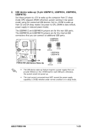
The USBPWR56 and USBPWR78 jumpers are for the rear USB ports. ASUS P5RD2-VM 1-23 2. Set to +5VSB to additional USB ports. The USBPWR12 and USBPWR34 jumpers are for each USB port; otherwise, the system would not power up ...from S1 sleep mode (CPU stopped, DRAM refreshed, system running in low power mode) using the connected USB devices. USBPW34 USBPW12 P5RD2-VM ® 2 1 +5V (Default) 3 2 +5VSB USBPW56 USBPW78 12 23 P5RD2-VM USB Device Wake-Up +5V (Default) +5VSB • The USB device wake-up the computer from S3 and S4 sleep modes...
The USBPWR56 and USBPWR78 jumpers are for the rear USB ports. ASUS P5RD2-VM 1-23 2. Set to +5VSB to additional USB ports. The USBPWR12 and USBPWR34 jumpers are for each USB port; otherwise, the system would not power up ...from S1 sleep mode (CPU stopped, DRAM refreshed, system running in low power mode) using the connected USB devices. USBPW34 USBPW12 P5RD2-VM ® 2 1 +5V (Default) 3 2 +5VSB USBPW56 USBPW78 12 23 P5RD2-VM USB Device Wake-Up +5V (Default) +5VSB • The USB device wake-up the computer from S3 and S4 sleep modes...

Motherboard Installation Guide
Page 37
.../2 mouse. 2. Parallel port. Line Out port (lime). In 4-channel, 6-channel configuration, the function of the audio ports in 2, 4, or 6-channel configuration. ASUS P5RD2-VM 1-25 Microphone port (pink). This port connects a microphone. 7. This 25-pin port connects a parallel printer, a scanner, or other audio sources. 5. This port connects a tape, CD...
.../2 mouse. 2. Parallel port. Line Out port (lime). In 4-channel, 6-channel configuration, the function of the audio ports in 2, 4, or 6-channel configuration. ASUS P5RD2-VM 1-25 Microphone port (pink). This port connects a microphone. 7. This 25-pin port connects a parallel printer, a scanner, or other audio sources. 5. This port connects a tape, CD...

Motherboard Installation Guide
Page 39
... as a slave device by setting its jumper accordingly. Refer to the hard disk documentation for Ultra DMA 100/66 IDE devices. PRI_IDE SEC_IDE P5RD2-VM ® P5RD2-VM IDE Connectors PIN 1 ASUS P5RD2-VM 1-27 If you install two hard disk drives, you connect the IDE cable. • Use the 80-conductor IDE cable for the jumper...
... as a slave device by setting its jumper accordingly. Refer to the hard disk documentation for Ultra DMA 100/66 IDE devices. PRI_IDE SEC_IDE P5RD2-VM ® P5RD2-VM IDE Connectors PIN 1 ASUS P5RD2-VM 1-27 If you install two hard disk drives, you connect the IDE cable. • Use the 80-conductor IDE cable for the jumper...

Motherboard Installation Guide
Page 41
...the fan connectors. CPU_FAN CPU FAN PWM CPU FAN IN CPU FAN PWR GND CHA_FAN2 Rotation +12V GND P5RD2-VM ® CHA_FAN1 Rotation +12V GND P5RD2-VM Fan Connectors 6. Do not forget to connect the fan cables to use the chassis intrusion detection feature. DO...matches the ground pin of the chassis intrusion sensor or switch cable to this connector. CHASSIS +5VSB_MB Chassis Signal GND P5RD2-VM ® (Default) P5RD2-VM Chassis Intrusion Connector ASUS P5RD2-VM 1-29 CPU and Chassis fan connectors (4-pin CPU_FAN, 3-pin CHA_FAN1, 3-pin CHA_FAN2) The fan connectors support cooling...
...the fan connectors. CPU_FAN CPU FAN PWM CPU FAN IN CPU FAN PWR GND CHA_FAN2 Rotation +12V GND P5RD2-VM ® CHA_FAN1 Rotation +12V GND P5RD2-VM Fan Connectors 6. Do not forget to connect the fan cables to use the chassis intrusion detection feature. DO...matches the ground pin of the chassis intrusion sensor or switch cable to this connector. CHASSIS +5VSB_MB Chassis Signal GND P5RD2-VM ® (Default) P5RD2-VM Chassis Intrusion Connector ASUS P5RD2-VM 1-29 CPU and Chassis fan connectors (4-pin CPU_FAN, 3-pin CHA_FAN1, 3-pin CHA_FAN2) The fan connectors support cooling...

Motherboard Installation Guide
Page 43
...These connectors are for USB 2.0 ports. USB+5V USB_P8USB_P8+ GND NC USB+5V USB_P6USB_P6+ GND NC USB+5V USB_P7USB_P7+ GND P5RD2-VM ® USB56 1 P5RD2-VM USB 2.0 Connectors USB+5V USB_P5USB_P5+ GND USB78 1 9. These USB connectors comply with USB 2.0 specification that supports ...pin AUX [white]) These connectors allow you to 480 Mbps connection speed. P5RD2-VM ® AUX (White) CD (Black) Right Audio Channel Ground Ground Left Audio Channel P5RD2-VM Internal Audio Connectors ASUS P5RD2-VM 1-31 Connect the optional USB module cable to any of these connectors, then...
...These connectors are for USB 2.0 ports. USB+5V USB_P8USB_P8+ GND NC USB+5V USB_P6USB_P6+ GND NC USB+5V USB_P7USB_P7+ GND P5RD2-VM ® USB56 1 P5RD2-VM USB 2.0 Connectors USB+5V USB_P5USB_P5+ GND USB78 1 9. These USB connectors comply with USB 2.0 specification that supports ...pin AUX [white]) These connectors allow you to 480 Mbps connection speed. P5RD2-VM ® AUX (White) CD (Black) Right Audio Channel Ground Ground Left Audio Channel P5RD2-VM Internal Audio Connectors ASUS P5RD2-VM 1-31 Connect the optional USB module cable to any of these connectors, then...

Motherboard Installation Guide
Page 45
... when data is read from or written to this connector. System panel connector (10-1 pin F_PANEL) This connector supports several chassis-mounted functions. P5RD2-VM System Panel Connector The sytem panel connector is for easy connection. Connect the HDD Activity LED cable to the connector description below for details. &#... is color-coded for the system power LED. Pressing the power button turns the system on the BIOS settings. PWR Ground Reset Ground P5RD2-VM ® IDE_LED RESET PWRSW * Requires an ATX power supply. 12. Refer to this connector. ASUS P5RD2-VM 1-33
... when data is read from or written to this connector. System panel connector (10-1 pin F_PANEL) This connector supports several chassis-mounted functions. P5RD2-VM System Panel Connector The sytem panel connector is for easy connection. Connect the HDD Activity LED cable to the connector description below for details. &#... is color-coded for the system power LED. Pressing the power button turns the system on the BIOS settings. PWR Ground Reset Ground P5RD2-VM ® IDE_LED RESET PWRSW * Requires an ATX power supply. 12. Refer to this connector. ASUS P5RD2-VM 1-33

Motherboard Installation Guide
Page 47
Detailed descriptions of the BIOS parameters are also provided. 2 BIOS setup ASUS P5RD2-VM 2-1 This chapter tells how to change the system settings through the BIOS Setup menus.
Detailed descriptions of the BIOS parameters are also provided. 2 BIOS setup ASUS P5RD2-VM 2-1 This chapter tells how to change the system settings through the BIOS Setup menus.

Motherboard Installation Guide
Page 49
e. Copy the original or the latest motherboard BIOS file to the bootable floppy disk. 2.1.2 ASUS EZ Flash utility The ASUS EZ Flash feature allows you rename the BIOS file to P5RD2VM.ROM. Save the BIOS file to continue. 2. Start erasing.......| Start programming...| Flashed ...;oppy disk. Rebooting. • Do not shutdown or reset the system while updating the BIOS to download the latest BIOS file for floppy... 4. ASUS P5RD2-VM 2-3 Visit the ASUS website (www.asus.com) to prevent system boot failure! • A "Floppy not found!"
e. Copy the original or the latest motherboard BIOS file to the bootable floppy disk. 2.1.2 ASUS EZ Flash utility The ASUS EZ Flash feature allows you rename the BIOS file to P5RD2VM.ROM. Save the BIOS file to continue. 2. Start erasing.......| Start programming...| Flashed ...;oppy disk. Rebooting. • Do not shutdown or reset the system while updating the BIOS to download the latest BIOS file for floppy... 4. ASUS P5RD2-VM 2-3 Visit the ASUS website (www.asus.com) to prevent system boot failure! • A "Floppy not found!"

Motherboard Installation Guide
Page 51
...) and download the latest BIOS file for the motherboard. A:\>afudos /iP5RD2VM.ROM AMI Firmware Update Utility - Version 1.10 Copyright (C) 2002 American Megatrends, Inc. done A:\> ASUS P5RD2-VM 2-5 done Erasing flash .... done Writing flash .... 0x0008CC00 (9%) Verifying flash .. done Writing flash .... 0x0008CC00 (9%) Do not shut down or reset the system...
...) and download the latest BIOS file for the motherboard. A:\>afudos /iP5RD2VM.ROM AMI Firmware Update Utility - Version 1.10 Copyright (C) 2002 American Megatrends, Inc. done A:\> ASUS P5RD2-VM 2-5 done Erasing flash .... done Writing flash .... 0x0008CC00 (9%) Verifying flash .. done Writing flash .... 0x0008CC00 (9%) Do not shut down or reset the system...


