
User Manual
Page 31
exe 2 DOS afudos /o[filename filename A:\>afudos /oOLDBIOS1.rom 3. 按下 afudos /oOLDBIOS1.rom AMI Firmware Update Utility - All rights reserved. Reading flash ..... ok A:\> 當 BIOS DOS 31 Version 1.19(ASUS V2.07(03.11.24BB)) Copyright (C) 2002 American Megatrends, Inc. done Write to file...... BIOS 2.1 使用 AFUDOS BIOS AFUDOS DOS BIOS BIOS 程式。AFUDOS BIOS BIOS BIOS 程式 BIOS 程式。 1.2MB BIOS 1 AFUDOS 程式(afudos.
exe 2 DOS afudos /o[filename filename A:\>afudos /oOLDBIOS1.rom 3. 按下 afudos /oOLDBIOS1.rom AMI Firmware Update Utility - All rights reserved. Reading flash ..... ok A:\> 當 BIOS DOS 31 Version 1.19(ASUS V2.07(03.11.24BB)) Copyright (C) 2002 American Megatrends, Inc. done Write to file...... BIOS 2.1 使用 AFUDOS BIOS AFUDOS DOS BIOS BIOS 程式。AFUDOS BIOS BIOS BIOS 程式 BIOS 程式。 1.2MB BIOS 1 AFUDOS 程式(afudos.

User Manual
Page 32
... American Megatrends, Inc. done Reading flash ...... done Writing flash ...... done BIOS 5. 當 BIOS DOS A:\>afudos /iP5B-VM DO.ROM AMI Firmware Update Utility - 更新 BIOS 程式 AFUDOS BIOS 程式。 1 tw.asus.com BIOS 片中。 BIOS BIOS 2. 將 AFUDOS.EXE BIOS 3 DOS afudos /i[filename filename BIOS 程式。 A:\>afudos /iP5B-VM DO.ROM 4. done...
... American Megatrends, Inc. done Reading flash ...... done Writing flash ...... done BIOS 5. 當 BIOS DOS A:\>afudos /iP5B-VM DO.ROM AMI Firmware Update Utility - 更新 BIOS 程式 AFUDOS BIOS 程式。 1 tw.asus.com BIOS 片中。 BIOS BIOS 2. 將 AFUDOS.EXE BIOS 3 DOS afudos /i[filename filename BIOS 程式。 A:\>afudos /iP5B-VM DO.ROM 4. done...

User Manual
Page 33
.../13/2006 Flash Type - 2.2 使用 AwardBIOS Flash BIOS AwardBIOS Flash AwardBIOS Flash 程式(AWDFLASH.EXE BIOS AwardBIOS Flash BIOS 程式。 1 http://tw.asus.com BIOS M2N-VM HDMI.bin FAT 32/16 格式的 USB BIOS 2 CD/DVD AwardBIOS Flash BIOS 3 DOS 4. 當 A BIOS 檔案與 AwardBIOS Flash 5 A awdflash 並按...
.../13/2006 Flash Type - 2.2 使用 AwardBIOS Flash BIOS AwardBIOS Flash AwardBIOS Flash 程式(AWDFLASH.EXE BIOS AwardBIOS Flash BIOS 程式。 1 http://tw.asus.com BIOS M2N-VM HDMI.bin FAT 32/16 格式的 USB BIOS 2 CD/DVD AwardBIOS Flash BIOS 3 DOS 4. 當 A BIOS 檔案與 AwardBIOS Flash 5 A awdflash 並按...

User Manual
Page 34
... Flash Type - OFE00 OK Write OK No Update Write Fail Warning: Don't Turn Off Power Or Reset System! 在更新 BIOS 9 Flash Complete BIOS F1 AwardBIOS Flash Utility for ASUS V1.14 (C) Phoenix Technologies Ltd. PMC Pm49FL004T LPC/FWH File Name to Continue Write OK F1 Reset No Update Write Fail 34...
... Flash Type - OFE00 OK Write OK No Update Write Fail Warning: Don't Turn Off Power Or Reset System! 在更新 BIOS 9 Flash Complete BIOS F1 AwardBIOS Flash Utility for ASUS V1.14 (C) Phoenix Technologies Ltd. PMC Pm49FL004T LPC/FWH File Name to Continue Write OK F1 Reset No Update Write Fail 34...
User Manual
Page 4
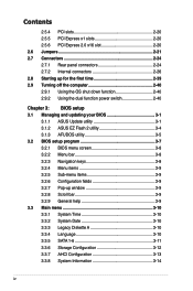
... the computer 2-40 2.9.1 Using the OS shut down function 2-40 2.9.2 Using the dual function power switch 2-40 Chapter 3: BIOS setup 3.1 Managing and updating your BIOS 3-1 3.1.1 ASUS Update utility 3-1 3.1.2 ASUS EZ Flash 2 utility 3-4 3.1.3 AFUDOS utility 3-5 3.2 BIOS setup program 3-7 3.2.1 BIOS menu screen 3-8 3.2.2 Menu bar 3-8 3.2.3 Navigation keys 3-8 3.2.4 Menu items 3-9 3.2.5 Sub-menu items 3-9 3.2.6 Configuration fields 3-9 3.2.7 Pop-up window 3-9 3.2.8 Scroll bar...
... the computer 2-40 2.9.1 Using the OS shut down function 2-40 2.9.2 Using the dual function power switch 2-40 Chapter 3: BIOS setup 3.1 Managing and updating your BIOS 3-1 3.1.1 ASUS Update utility 3-1 3.1.2 ASUS EZ Flash 2 utility 3-4 3.1.3 AFUDOS utility 3-5 3.2 BIOS setup program 3-7 3.2.1 BIOS menu screen 3-8 3.2.2 Menu bar 3-8 3.2.3 Navigation keys 3-8 3.2.4 Menu items 3-9 3.2.5 Sub-menu items 3-9 3.2.6 Configuration fields 3-9 3.2.7 Pop-up window 3-9 3.2.8 Scroll bar...
User Manual
Page 10
...documentation, such as warranty flyers, that may have to change system settings through the BIOS Setup menus. ASUS websites The ASUS website provides updated information on the motherboard. • Chapter 3: BIOS setup This chapter tells how to perform when installing system components. Refer to the following... This user guide contains the information you have been added by your dealer. Detailed descriptions of the BIOS parameters are not part of the motherboard and the new technology it supports. • Chapter 2: Hardware information This chapter lists the hardware setup...
...documentation, such as warranty flyers, that may have to change system settings through the BIOS Setup menus. ASUS websites The ASUS website provides updated information on the motherboard. • Chapter 3: BIOS setup This chapter tells how to perform when installing system components. Refer to the following... This user guide contains the information you have been added by your dealer. Detailed descriptions of the BIOS parameters are not part of the motherboard and the new technology it supports. • Chapter 2: Hardware information This chapter lists the hardware setup...

User Manual
Page 13
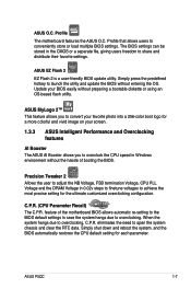
... Parameter Recall) (continued on the next page) xiii ASUS AI Nap ASUS AI Life Features: - ASUS CrashFree BIOS 3 - ASUS Q-Connector - ASUS Fan Xpert ASUS EZ DIY: - ASUS 3rd Generation 8-Phase Power Design - ASUS EPU-6 Engine - vCore: Adjustable CPU voltage at 1MHz increment - Profile - P5QC specifications summary ASUS Unique features ASUS Exclusive Overclocking Features ASUS Power Saving Solution: - vFSB Termination: 15-step Hyper Transport...
... Parameter Recall) (continued on the next page) xiii ASUS AI Nap ASUS AI Life Features: - ASUS CrashFree BIOS 3 - ASUS Q-Connector - ASUS Fan Xpert ASUS EZ DIY: - ASUS 3rd Generation 8-Phase Power Design - ASUS EPU-6 Engine - vCore: Adjustable CPU voltage at 1MHz increment - Profile - P5QC specifications summary ASUS Unique features ASUS Exclusive Overclocking Features ASUS Power Saving Solution: - vFSB Termination: 15-step Hyper Transport...
User Manual
Page 14
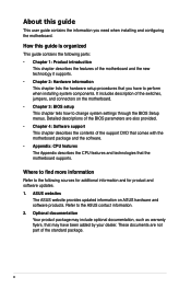
P5QC specifications summary Back Panel I/O Ports 1 x PS/2 keyboard port (Purple) 1 x PS/2 mouse port (Green) 1 x S/PDIF Out (Coaxial) 1 x IEEE1394a port 1 x RJ45 port 6 x USB 2.0/1.1 ports 8-channel Audio I/O ports ... Chassis Intrusion connector CD audio in 24-pin ATX Power connector 8-pin ATX 12V Power connectors System Panel (Q-Connector) BIOS Features 8 Mb AMI BIOS, PnP, DMI 2.0, WfM 2.0, SM BIOS 2.4 Manageability WOL by PME, WOR by PME, WOR by Ring, PXE, Support DVD Contents Drivers ASUS PC Probe II ASUS Update ASUS AI Suite Image-Editing Suite Anti-virus...
P5QC specifications summary Back Panel I/O Ports 1 x PS/2 keyboard port (Purple) 1 x PS/2 mouse port (Green) 1 x S/PDIF Out (Coaxial) 1 x IEEE1394a port 1 x RJ45 port 6 x USB 2.0/1.1 ports 8-channel Audio I/O ports ... Chassis Intrusion connector CD audio in 24-pin ATX Power connector 8-pin ATX 12V Power connectors System Panel (Q-Connector) BIOS Features 8 Mb AMI BIOS, PnP, DMI 2.0, WfM 2.0, SM BIOS 2.4 Manageability WOL by PME, WOR by PME, WOR by Ring, PXE, Support DVD Contents Drivers ASUS PC Probe II ASUS Update ASUS AI Suite Image-Editing Suite Anti-virus...

User Manual
Page 22
...electric conductivity, it against Electronic Magnetic Interference (EMI). saving up your motherboard against static electricity and shields it ideally protects your favorite settings. ASUS Drive Xpert Without drivers or BIOS setups, the ASUS exclusive Drive Xpert is looked after every moment, every day. making ... allows you easy ways to the motherboard. ASUS EZ DIY ASUS EZ DIY feature collection provides you to easily connect or disconnect the chassis front panel cables to install computer components, update the BIOS or back up to backup or share large data files ...
...electric conductivity, it against Electronic Magnetic Interference (EMI). saving up your motherboard against static electricity and shields it ideally protects your favorite settings. ASUS Drive Xpert Without drivers or BIOS setups, the ASUS exclusive Drive Xpert is looked after every moment, every day. making ... allows you easy ways to the motherboard. ASUS EZ DIY ASUS EZ DIY feature collection provides you to easily connect or disconnect the chassis front panel cables to install computer components, update the BIOS or back up to backup or share large data files ...
User Manual
Page 23
... to overclocking, C.P.R. Simply shut down and reboot the system, and the BIOS automatically restores the CPU default setting for the ultimate customized overclocking configuration. When the system hangs due to share and distribute their favorite settings. ASUS P5QC 1-7 Simply press the predefined hotkey to overclocking. ASUS O.C. Profile The motherboard features the ASUS O.C. feature of booting the...
... to overclocking, C.P.R. Simply shut down and reboot the system, and the BIOS automatically restores the CPU default setting for the ultimate customized overclocking configuration. When the system hangs due to share and distribute their favorite settings. ASUS P5QC 1-7 Simply press the predefined hotkey to overclocking. ASUS O.C. Profile The motherboard features the ASUS O.C. feature of booting the...
User Manual
Page 44
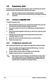
... you intend to do not need to install expansion cards. 2.5 Expansion slots In the future, you may cause you physical injury and damage motherboard components. 2.5.1 Installing an�e���x��p��a�n�s�i�o�n�c��a�rd� To... an expansion card: 1. Refer to unplug the power cord before adding or removing expansion cards. Refer to the card. Turn on BIOS setup. 2. Assign an IRQ to the table on the next page for information on the system and change the necessary...
... you intend to do not need to install expansion cards. 2.5 Expansion slots In the future, you may cause you physical injury and damage motherboard components. 2.5.1 Installing an�e���x��p��a�n�s�i�o�n�c��a�rd� To... an expansion card: 1. Refer to unplug the power cord before adding or removing expansion cards. Refer to the card. Turn on BIOS setup. 2. Assign an IRQ to the table on the next page for information on the system and change the necessary...
User Manual
Page 47
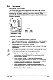
...4. To erase the RTC RAM 1. Plug the power cord and turn off is required to pins 1-2. 3. Hold down and reboot the system so the BIOS can clear the CMOS memory of date, time, and system setup parameters by erasing the CMOS RTC RAM data. The onboard button cell battery powers...seconds, then move the jumper again to clear the Real Time Clock (RTC) RAM in CMOS, which include system setup information such as system passwords. ASUS P5QC 2-21 2.6 Jumpers 1. Clear RTC RAM (3-pin CLRTC) This jumper allows you to clear the CMOS RTC RAM data. You can automatically reset parameter ...
...4. To erase the RTC RAM 1. Plug the power cord and turn off is required to pins 1-2. 3. Hold down and reboot the system so the BIOS can clear the CMOS memory of date, time, and system setup parameters by erasing the CMOS RTC RAM data. The onboard button cell battery powers...seconds, then move the jumper again to clear the Real Time Clock (RTC) RAM in CMOS, which include system setup information such as system passwords. ASUS P5QC 2-21 2.6 Jumpers 1. Clear RTC RAM (3-pin CLRTC) This jumper allows you to clear the CMOS RTC RAM data. You can automatically reset parameter ...
User Manual
Page 48
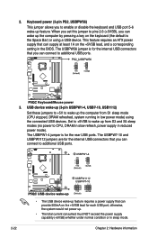
... and USB port 5-6 wake-up . • The total current consumed must NOT exceed the power supply capability (+5VSB) whether under normal condition or in the BIOS. This feature requires an ATX power supply that you can provide 500mA on the +5VSB lead, and a corresponding setting in sleep mode. 2-22 Chapter 2: Hardware information
... and USB port 5-6 wake-up . • The total current consumed must NOT exceed the power supply capability (+5VSB) whether under normal condition or in the BIOS. This feature requires an ATX power supply that you can provide 500mA on the +5VSB lead, and a corresponding setting in sleep mode. 2-22 Chapter 2: Hardware information

User Manual
Page 49
...the computer and move the cap back to pins 2-3. • The system may cause the system to work stably under the highest BIOS voltage settings before you change the jumper settings for more information about CPU and Northbridge overvoltage settings. • DO NOT set the ...failure due to the wrong setting of these two jumpers. • Refer to 3.4 Ai Tweaker for extra-high overvoltage ability, use the BIOS items introduced in BIOS. ASUS P5QC 2-23 4. Read the following information before you install a new CPU and have not booted for example, a water-cooling system) to ...
...the computer and move the cap back to pins 2-3. • The system may cause the system to work stably under the highest BIOS voltage settings before you change the jumper settings for more information about CPU and Northbridge overvoltage settings. • DO NOT set the ...failure due to the wrong setting of these two jumpers. • Refer to 3.4 Ai Tweaker for extra-high overvoltage ability, use the BIOS items introduced in BIOS. ASUS P5QC 2-23 4. Read the following information before you install a new CPU and have not booted for example, a water-cooling system) to ...

User Manual
Page 54
...can connect Serial ATA boot/data hard disk drives to these connectors, set to [AHCI]. 4. If you are set the Configure SATA as in the BIOS to Standard IDE mode by default. See section 3.3.6 Storage Configuration for details. • Before creating a RAID set, refer to avoid mechanical conflict with... feature (RAID 0, 1, 5, and 10) is available only if you intend to create a Serial ATA RAID set the Configure SATA as item in the motherboard support DVD. • You must install the Windows® XP Service Pack 1 before using hot-plug and NCQ, set using these connectors.
...can connect Serial ATA boot/data hard disk drives to these connectors, set to [AHCI]. 4. If you are set the Configure SATA as in the BIOS to Standard IDE mode by default. See section 3.3.6 Storage Configuration for details. • Before creating a RAID set, refer to avoid mechanical conflict with... feature (RAID 0, 1, 5, and 10) is available only if you intend to create a Serial ATA RAID set the Configure SATA as item in the motherboard support DVD. • You must install the Windows® XP Service Pack 1 before using hot-plug and NCQ, set using these connectors.
User Manual
Page 60
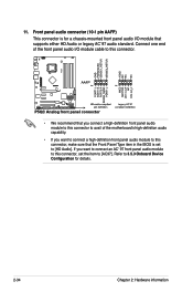
... /O module cable to this connector. • We recommend that you connect a high-definition front panel audio module to this connector to avail of the motherboard's high-definition audio capability. • If you want to connect a high-definition front panel audio module to this connector, set to [AC97]. If you... AC`97 audio standard. 11. Connect one end of the front panel audio I /O module that the Front Panel Type item in the BIOS is for details. 2-34 Chapter 2: Hardware information Front panel audio connector (10-1 pin AAFP) This connector is set the item to [HD Audio]....
... /O module cable to this connector. • We recommend that you connect a high-definition front panel audio module to this connector to avail of the motherboard's high-definition audio capability. • If you want to connect a high-definition front panel audio module to this connector, set to [AC97]. If you... AC`97 audio standard. 11. Connect one end of the front panel audio I /O module that the Front Panel Type item in the BIOS is for details. 2-34 Chapter 2: Hardware information Front panel audio connector (10-1 pin AAFP) This connector is set the item to [HD Audio]....
User Manual
Page 63
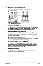
... 2-pin connector is for system reboot without turning off mode depending on the BIOS settings. Pressing the power switch for the HDD Activity LED. ASUS P5QC 2-37 Connect the HDD Activity LED cable to hear system beeps and warnings. • ATX power button/soft-off button (2-pin PWRSW) This connector is for more than...
... 2-pin connector is for system reboot without turning off mode depending on the BIOS settings. Pressing the power switch for the HDD Activity LED. ASUS P5QC 2-37 Connect the HDD Activity LED cable to hear system beeps and warnings. • ATX power button/soft-off button (2-pin PWRSW) This connector is for more than...
User Manual
Page 65
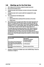
...retailer for the first time 1. Check the jumper settings and connections or call your monitor complies with the last device on the devices in Chapter 3. ASUS P5QC 2-39 For systems with a surge protector. 5. Turn on the chain) c. The system then runs the power-on test. While the tests are ... or additional messages appear on . After making all switches are running, the BIOS beeps (see anything within 30 seconds from the time you press the ATX power button. Be sure that is equipped with ATX power supplies, the system LED lights up or switch between orange and green after...
...retailer for the first time 1. Check the jumper settings and connections or call your monitor complies with the last device on the devices in Chapter 3. ASUS P5QC 2-39 For systems with a surge protector. 5. Turn on the chain) c. The system then runs the power-on test. While the tests are ... or additional messages appear on . After making all switches are running, the BIOS beeps (see anything within 30 seconds from the time you press the ATX power button. Be sure that is equipped with ATX power supplies, the system LED lights up or switch between orange and green after...
User Manual
Page 66
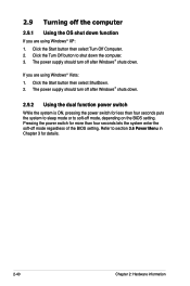
... the computer. 3. Pressing the power switch for more than four seconds puts the system to sleep mode or to soft-off mode, depending on the BIOS setting. Refer to shut down . 2.9 Turning off the computer 2.9.1 Using the OS shut down function If you are using Windows® Vista: 1. The power supply... Turn Off button to section 3.6 Power Menu in Chapter 3 for less than four seconds lets the system enter the soft-off mode regardless of the BIOS setting.
... the computer. 3. Pressing the power switch for more than four seconds puts the system to sleep mode or to soft-off mode, depending on the BIOS setting. Refer to shut down . 2.9 Turning off the computer 2.9.1 Using the OS shut down function If you are using Windows® Vista: 1. The power supply... Turn Off button to section 3.6 Power Menu in Chapter 3 for less than four seconds lets the system enter the soft-off mode regardless of the BIOS setting.
User Manual
Page 67
This chapter tells how to change the BIOS se3tup system settings through the BIOS Setup menus. Detailed descriptions of the BIOS parameters are also provided.
This chapter tells how to change the BIOS se3tup system settings through the BIOS Setup menus. Detailed descriptions of the BIOS parameters are also provided.


