P5P800 User's manual English Edition E1906
Page 8
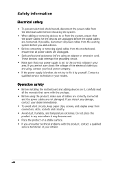
.... • Before connecting or removing signal cables from the motherboard, ensure that all power cables from the existing system before you are using, contact your local power company. • If the power supply is set to the correct voltage in any area where it may become wet. &#...8226; Avoid dust, humidity, and temperature extremes. Contact a qualified service technician or your power supply is broken, do not try to fix it , carefully read all cables are correctly connected and the power cables are not damaged. viii If you encounter technical problems with the package. •...
.... • Before connecting or removing signal cables from the motherboard, ensure that all power cables from the existing system before you are using, contact your local power company. • If the power supply is set to the correct voltage in any area where it may become wet. &#...8226; Avoid dust, humidity, and temperature extremes. Contact a qualified service technician or your power supply is broken, do not try to fix it , carefully read all cables are correctly connected and the power cables are not damaged. viii If you encounter technical problems with the package. •...

P5P800 User's manual English Edition E1906
Page 12
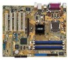
P5P800 specifications summary Rear panel Internal connectors Power Requirement Form Factor Support CD contents 1 x Parallel port 1 x Serial port 1 x LAN (RJ-45) port 4 x USB 2.0 ports 1 x S/PDIF out port 1 x PS/2 keyboard port 1 x PS/2 mouse port... connector 1 x Front panel audio connector 1 x S/PDIF out connector System panel connector ATX power supply (with 24-pin and 4-pin 12 V plugs) ATX 12 V 2.0 compliant ATX form factor: 12 in x 9.6 in (30.5 cm x 24.4 cm) Device drivers ASUS PC Probe ASUS Live Update Utility Anti-virus software (OEM version) *Specifications are subject to change...
P5P800 specifications summary Rear panel Internal connectors Power Requirement Form Factor Support CD contents 1 x Parallel port 1 x Serial port 1 x LAN (RJ-45) port 4 x USB 2.0 ports 1 x S/PDIF out port 1 x PS/2 keyboard port 1 x PS/2 mouse port... connector 1 x Front panel audio connector 1 x S/PDIF out connector System panel connector ATX power supply (with 24-pin and 4-pin 12 V plugs) ATX 12 V 2.0 compliant ATX form factor: 12 in x 9.6 in (30.5 cm x 24.4 cm) Device drivers ASUS PC Probe ASUS Live Update Utility Anti-virus software (OEM version) *Specifications are subject to change...
P5P800 User's manual English Edition E1906
Page 21
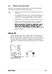
...8226; Before you install or remove any component, ensure that the ATX power supply is ON, in sleep mode, or in the bag that came with a standby power LED that lights up to the motherboard, peripherals, and/or components. ...power supply case, before handling components to avoid damaging them due to static electricity • Hold components by the edges to avoid touching the ICs on them. • Whenever you uninstall any motherboard component. 2.1 Before you proceed Take note of the onboard LED. ® P5P800 P5P800 Onboard LED SB_PWR ON Standby Power OFF Powered Off ASUS P5P800...
...8226; Before you install or remove any component, ensure that the ATX power supply is ON, in sleep mode, or in the bag that came with a standby power LED that lights up to the motherboard, peripherals, and/or components. ...power supply case, before handling components to avoid damaging them due to static electricity • Hold components by the edges to avoid touching the ICs on them. • Whenever you uninstall any motherboard component. 2.1 Before you proceed Take note of the onboard LED. ® P5P800 P5P800 Onboard LED SB_PWR ON Standby Power OFF Powered Off ASUS P5P800...
P5P800 User's manual English Edition E1906
Page 33
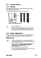
...Memory Modules (DIMM) sockets. Make sure that you obtain memory modules from the same vendor. ASUS P5P800 2-13 Failure to do so may cause severe damage to unplug the power supply before adding or removing DIMMs or other system components. Always install DIMMs with the same CAS Latency.... 4. The following figure illustrates the location of the sockets: DIMM_A1 DIMM_A2 DIMM_B1 DIMM_B2 ® P5P800 P5P800 184-Pin DDR DIMM Sockets ...
...Memory Modules (DIMM) sockets. Make sure that you obtain memory modules from the same vendor. ASUS P5P800 2-13 Failure to do so may cause severe damage to unplug the power supply before adding or removing DIMMs or other system components. Always install DIMMs with the same CAS Latency.... 4. The following figure illustrates the location of the sockets: DIMM_A1 DIMM_A2 DIMM_B1 DIMM_B2 ® P5P800 P5P800 184-Pin DDR DIMM Sockets ...

P5P800 User's manual English Edition E1906
Page 36
... both the motherboard and the components. 1. Remove the DIMM from the socket. 2-16 Chapter 2: Hardware information Simultaneously press the retaining clips outward to unplug the power supply before adding or removing DIMMs or other system components. 2.4.3 Installing a DIMM Make sure to unlock the DIMM. 1 1 DDR DIMM notch Support the DIMM lightly with...
... both the motherboard and the components. 1. Remove the DIMM from the socket. 2-16 Chapter 2: Hardware information Simultaneously press the retaining clips outward to unplug the power supply before adding or removing DIMMs or other system components. 2.4.3 Installing a DIMM Make sure to unlock the DIMM. 1 1 DDR DIMM notch Support the DIMM lightly with...
P5P800 User's manual English Edition E1906
Page 41
... is for the internal USB connectors that you can connect to CPU, DRAM in slow refresh, power supply in reduced power mode). ASUS P5P800 2-21 The USBPWR12 and USBPWR34 jumpers are for each USB port; otherwise, the system would not power up from S1 sleep mode (CPU stopped, DRAM refreshed, system running in sleep mode. Set...
... is for the internal USB connectors that you can connect to CPU, DRAM in slow refresh, power supply in reduced power mode). ASUS P5P800 2-21 The USBPWR12 and USBPWR34 jumpers are for each USB port; otherwise, the system would not power up from S1 sleep mode (CPU stopped, DRAM refreshed, system running in sleep mode. Set...
P5P800 User's manual English Edition E1906
Page 42
This feature requires an ATX power supply that can supply at least 1A on the keyboard (the default is the Space Bar). KBPWR 12 23 +5V +5VSB (Default) R P5P800 P5P800 Keyboard power setting 2-22 Chapter 2: Hardware information Set this jumper to pins 2-3 (+5VSB) if you press a key on the +5VSB lead, and a corresponding setting in the BIOS. 3. Keyboard power (3-pin KBPWR) This jumper allows you to wake up the computer when you wish to enable or disable the keyboard wake-up feature.
This feature requires an ATX power supply that can supply at least 1A on the keyboard (the default is the Space Bar). KBPWR 12 23 +5V +5VSB (Default) R P5P800 P5P800 Keyboard power setting 2-22 Chapter 2: Hardware information Set this jumper to pins 2-3 (+5VSB) if you press a key on the +5VSB lead, and a corresponding setting in the BIOS. 3. Keyboard power (3-pin KBPWR) This jumper allows you to wake up the computer when you wish to enable or disable the keyboard wake-up feature.

P5P800 User's manual English Edition E1906
Page 49
... ® P5P800 +12V DC GND P5P800 ATX power connector EATXPWR +3 Volts -12 Volts Ground PSON# Ground Ground Ground -5 Volts +5 Volts +5 Volts +5 Volts Ground +3 Volts +3 Volts Ground +5 Volts Ground +5 Volts Ground Power OK +5V Standby +12 Volts +12 Volts +3 Volts 2-30 Chapter 2: Hardware information The minimum recommended wattage is inadequate. • You must install a Power Supply Unit...
... ® P5P800 +12V DC GND P5P800 ATX power connector EATXPWR +3 Volts -12 Volts Ground PSON# Ground Ground Ground -5 Volts +5 Volts +5 Volts +5 Volts Ground +3 Volts +3 Volts Ground +5 Volts Ground +5 Volts Ground Power OK +5V Standby +12 Volts +12 Volts +3 Volts 2-30 Chapter 2: Hardware information The minimum recommended wattage is inadequate. • You must install a Power Supply Unit...
P5P800 User's manual English Edition E1906
Page 53
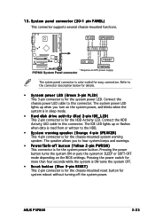
...pin PANEL) This connector supports several chassis-mounted functions. PWR Ground Reset Ground ® P5P800 IDE_LED RESET PWRSW * Requires an ATX power supply. The system power LED lights up or flashes when data is read from or written to the connector ...power, and blinks when the system is in sleep mode. • Hard disk drive activity (Red 2-pin IDE_LED) This 2-pin connector is for the HDD Activity LED. 13. Refer to the HDD. • System warning speaker (Orange 4-pin SPEAKER) This 4-pin connector is for the chassis-mounted system warning speaker. ASUS P5P800...
...pin PANEL) This connector supports several chassis-mounted functions. PWR Ground Reset Ground ® P5P800 IDE_LED RESET PWRSW * Requires an ATX power supply. The system power LED lights up or flashes when data is read from or written to the connector ...power, and blinks when the system is in sleep mode. • Hard disk drive activity (Red 2-pin IDE_LED) This 2-pin connector is for the HDD Activity LED. 13. Refer to the HDD. • System warning speaker (Orange 4-pin SPEAKER) This 4-pin connector is for the chassis-mounted system warning speaker. ASUS P5P800...
P5P800 User's manual English Edition E1906
Page 57
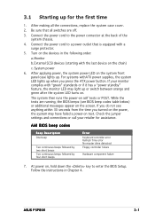
...messages appear on test. Follow the instructions in the following order: a. For systems withATX power supplies, the system LED lights up when you turned on the power, the system may light up . Connect the power cord to enter the BIOS Setup. Turn on , hold down the key to the... 4. External SCSI devices (starting with "green" standards or if it has a "power standby" feature, the monitor LED may have failed a power-on the screen. The system then runs the power-on the chain) c. ASUS P5P800 3-1 AMI BIOS beep codes Beep Description One beep Two continuous beeps followed by two ...
...messages appear on test. Follow the instructions in the following order: a. For systems withATX power supplies, the system LED lights up when you turned on the power, the system may light up . Connect the power cord to enter the BIOS Setup. Turn on , hold down the key to the... 4. External SCSI devices (starting with "green" standards or if it has a "power standby" feature, the monitor LED may have failed a power-on the screen. The system then runs the power-on the chain) c. ASUS P5P800 3-1 AMI BIOS beep codes Beep Description One beep Two continuous beeps followed by two ...
P5P800 User's manual English Edition E1906
Page 58
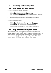
...: 1. Make sure that the S h u t D o w n option button is ON, pressing the power switch for less than four seconds lets the system enter the soft-off after Windows® shuts down . The power supply should turn off mode regardless of the BIOS setting. Click the T u r n O f f button to... then click the O K button to shut down the computer. 3. The power supply should turn off mode, depending on the BIOS setting. Pressing the power switch for details. 3-2 Chapter 3: Powering up Refer to section "4.5 Power Menu" in Chapter 4 for more than four seconds puts the system to sleep...
...: 1. Make sure that the S h u t D o w n option button is ON, pressing the power switch for less than four seconds lets the system enter the soft-off after Windows® shuts down . The power supply should turn off mode regardless of the BIOS setting. Click the T u r n O f f button to... then click the O K button to shut down the computer. 3. The power supply should turn off mode, depending on the BIOS setting. Pressing the power switch for details. 3-2 Chapter 3: Powering up Refer to section "4.5 Power Menu" in Chapter 4 for more than four seconds puts the system to sleep...

P5P800 User's manual English Edition E1906
Page 92
... this parameter allows you to use specific keys on the keyboard to turn on the system. This feature requires an ATX power supply that turns the system power on. Turning an external modem off and then back on while the computer is in Soft-off causes an initialization string...] [Enabled] 4-32 Chapter 4: BIOS setup This feature requires an ATX power supply that provides at least 1A on the first try. Power On By External Modems [Disabled] This allows either settings of [Enabled] or [Disabled] for powering up the computer when the external modem receives a call while the computer is...
... this parameter allows you to use specific keys on the keyboard to turn on the system. This feature requires an ATX power supply that turns the system power on. Turning an external modem off and then back on while the computer is in Soft-off causes an initialization string...] [Enabled] 4-32 Chapter 4: BIOS setup This feature requires an ATX power supply that provides at least 1A on the first try. Power On By External Modems [Disabled] This allows either settings of [Enabled] or [Disabled] for powering up the computer when the external modem receives a call while the computer is...

P5P800 User's manual English Edition E1726
Page 8
... any damage, contact your retailer. If you are unplugged. • Seek professional assistance before using the product, make sure all power cables are using, contact your local power company. • If the power supply is broken, do not try to or from connectors, slots, sockets and circuitry. • Avoid dust, humidity, and temperature extremes...
... any damage, contact your retailer. If you are unplugged. • Seek professional assistance before using the product, make sure all power cables are using, contact your local power company. • If the power supply is broken, do not try to or from connectors, slots, sockets and circuitry. • Avoid dust, humidity, and temperature extremes...

P5P800 User's manual English Edition E1726
Page 12
P5P800 specifications summary Rear panel Internal connectors Power Requirement Form Factor Support CD contents 1 x Parallel port 1 x Serial port 1 x LAN (RJ-45) port 4 x USB 2.0 ports 1 x S/PDIF out port 1 x PS/2 keyboard port 1 x PS/2 mouse port... connector 1 x Front panel audio connector 1 x S/PDIF out connector System panel connector ATX power supply (with 24-pin and 4-pin 12 V plugs) ATX 12 V 2.0 compliant ATX form factor: 12 in x 9.6 in (30.5 cm x 24.4 cm) Device drivers ASUS PC Probe ASUS Live Update Utility Anti-virus software (OEM version) *Specifications are subject to change...
P5P800 specifications summary Rear panel Internal connectors Power Requirement Form Factor Support CD contents 1 x Parallel port 1 x Serial port 1 x LAN (RJ-45) port 4 x USB 2.0 ports 1 x S/PDIF out port 1 x PS/2 keyboard port 1 x PS/2 mouse port... connector 1 x Front panel audio connector 1 x S/PDIF out connector System panel connector ATX power supply (with 24-pin and 4-pin 12 V plugs) ATX 12 V 2.0 compliant ATX form factor: 12 in x 9.6 in (30.5 cm x 24.4 cm) Device drivers ASUS PC Probe ASUS Live Update Utility Anti-virus software (OEM version) *Specifications are subject to change...

P5P800 User's manual English Edition E1726
Page 21
... component, ensure that the ATX power supply is ON, in sleep mode, or in the bag that the system is switched off mode. 2.1 Before you proceed Take note of the onboard LED. ® P5P800 P5P800 Onboard LED SB_PWR ON Standby Power OFF Powered Off ASUS P5P800 2-1 Onboard LED The motherboard comes with a standby power LED that lights up to...
... component, ensure that the ATX power supply is ON, in sleep mode, or in the bag that the system is switched off mode. 2.1 Before you proceed Take note of the onboard LED. ® P5P800 P5P800 Onboard LED SB_PWR ON Standby Power OFF Powered Off ASUS P5P800 2-1 Onboard LED The motherboard comes with a standby power LED that lights up to...
P5P800 User's manual English Edition E1726
Page 31
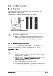
ASUS P5P800 2-11 Important notes 1. Make.../ C P U F S B s y n c h r o n i z a t i o n table on page 2-12. 2. The following figure illustrates the location of the sockets: DIMM_A1 DIMM_A2 DIMM_B1 DIMM_B2 ® P5P800 P5P800 184-Pin DDR DIMM Sockets • Use the blue DIMM slots first. • Make sure to both the motherboard and the components. 2.4.2 Memory configurations You...memory configurations in this section. Failure to do so may cause severe damage to unplug the power supply before adding or removing DIMMs or other system components. 2.4 System memory 2.4.1 Overview The ...
ASUS P5P800 2-11 Important notes 1. Make.../ C P U F S B s y n c h r o n i z a t i o n table on page 2-12. 2. The following figure illustrates the location of the sockets: DIMM_A1 DIMM_A2 DIMM_B1 DIMM_B2 ® P5P800 P5P800 184-Pin DDR DIMM Sockets • Use the blue DIMM slots first. • Make sure to both the motherboard and the components. 2.4.2 Memory configurations You...memory configurations in this section. Failure to do so may cause severe damage to unplug the power supply before adding or removing DIMMs or other system components. 2.4 System memory 2.4.1 Overview The ...

P5P800 User's manual English Edition E1726
Page 34
... clips outward to unlock the DIMM. 1 1 DDR DIMM notch Support the DIMM lightly with extra force. 2. Firmly insert the DIMM into a socket to unplug the power supply before adding or removing DIMMs or other system components. Remove the DIMM from the socket. 2-14 Chapter 2: Hardware information Unlock a DIMM socket by pressing the...
... clips outward to unlock the DIMM. 1 1 DDR DIMM notch Support the DIMM lightly with extra force. 2. Firmly insert the DIMM into a socket to unplug the power supply before adding or removing DIMMs or other system components. Remove the DIMM from the socket. 2-14 Chapter 2: Hardware information Unlock a DIMM socket by pressing the...

P5P800 User's manual English Edition E1726
Page 39
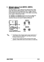
...ASUS P5P800 2-19 The USBPWR12 and USBPWR34 jumpers are for each USB port; 2 . USB device wake-up (3-pin USBPW12, USBPW34, USBPW56, USBPW78) Set these jumpers to +5V to wake up the computer from S3 and S4 sleep modes (no power to CPU, DRAM in slow refresh, power supply in reduced power ...mode. Set to +5VSB to additional USB ports. ® P5P800 USBPW12 USBPW34 3 2 2 1 +5V (Default) +5VSB USBPW56 USBPW78 12 23 P5P800 USB device wake up +5V (Default) +5VSB • The USB device wake-up feature requires a power supply that you can provide 500mA on the +5VSB lead for the ...
...ASUS P5P800 2-19 The USBPWR12 and USBPWR34 jumpers are for each USB port; 2 . USB device wake-up (3-pin USBPW12, USBPW34, USBPW56, USBPW78) Set these jumpers to +5V to wake up the computer from S3 and S4 sleep modes (no power to CPU, DRAM in slow refresh, power supply in reduced power ...mode. Set to +5VSB to additional USB ports. ® P5P800 USBPW12 USBPW34 3 2 2 1 +5V (Default) +5VSB USBPW56 USBPW78 12 23 P5P800 USB device wake up +5V (Default) +5VSB • The USB device wake-up feature requires a power supply that you can provide 500mA on the +5VSB lead for the ...

P5P800 User's manual English Edition E1726
Page 40
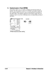
Keyboard power (3-pin KBPWR) This jumper allows you press a key on the +5VSB lead, and a corresponding setting in the BIOS. KBPWR 12 23 +5V +5VSB (Default) R P5P800 P5P800 Keyboard power setting 2-20 Chapter 2: Hardware information Set this jumper to pins 2-3 (+5VSB) if you wish to enable or disable the keyboard wake-up the computer when you to wake up feature. 3. This feature requires an ATX power supply that can supply at least 1A on the keyboard (the default is the Space Bar).
Keyboard power (3-pin KBPWR) This jumper allows you press a key on the +5VSB lead, and a corresponding setting in the BIOS. KBPWR 12 23 +5V +5VSB (Default) R P5P800 P5P800 Keyboard power setting 2-20 Chapter 2: Hardware information Set this jumper to pins 2-3 (+5VSB) if you wish to enable or disable the keyboard wake-up the computer when you to wake up feature. 3. This feature requires an ATX power supply that can supply at least 1A on the keyboard (the default is the Space Bar).

P5P800 User's manual English Edition E1726
Page 48
... push down firmly until the connectors completely fit. • Do not forget to install additional devices. ATX12V +12V DC GND ® P5P800 +12V DC GND P5P800 ATX power connector EATXPWR +3 Volts -12 Volts Ground PSON# Ground Ground Ground -5 Volts +5 Volts +5 Volts +5 Volts Ground +3 Volts +3 Volts... will not boot up if the power is 300 W, or 350 W for an ATX power supply. The plugs from the power supply are for a fully configured system. The minimum recommended wattage is inadequate. • You must install a Power Supply Unit (PSU) with 20-pin power plug, make sure that it can...
... push down firmly until the connectors completely fit. • Do not forget to install additional devices. ATX12V +12V DC GND ® P5P800 +12V DC GND P5P800 ATX power connector EATXPWR +3 Volts -12 Volts Ground PSON# Ground Ground Ground -5 Volts +5 Volts +5 Volts +5 Volts Ground +3 Volts +3 Volts... will not boot up if the power is 300 W, or 350 W for an ATX power supply. The plugs from the power supply are for a fully configured system. The minimum recommended wattage is inadequate. • You must install a Power Supply Unit (PSU) with 20-pin power plug, make sure that it can...


