User Manual
Page 3
... vii About this guide viii P5P41T LE specifications summary ix Chapter 1: Product introduction 1.1 Welcome 1-1 1.2 Package contents 1-1 1.3 Special features 1-1 1.3.1 Product highlights 1-1 1.3.2 Innovative ASUS features 1-2 1.4 Before you proceed 1-4 1.5 Motherboard overview 1-5 1.5.1 Placement direction 1-5 1.5.2 Screw holes 1-5 1.5.3 Motherboard layout 1-6 1.5.4 Layout contents 1-6 1.6 Central Processing Unit (CPU 1-7 1.6.1 Installing the CPU 1-7 1.6.2 Installing the CPU heatsink and fan 1-10 1.6.3 Uninstalling the CPU heatsink and fan 1-11...
... vii About this guide viii P5P41T LE specifications summary ix Chapter 1: Product introduction 1.1 Welcome 1-1 1.2 Package contents 1-1 1.3 Special features 1-1 1.3.1 Product highlights 1-1 1.3.2 Innovative ASUS features 1-2 1.4 Before you proceed 1-4 1.5 Motherboard overview 1-5 1.5.1 Placement direction 1-5 1.5.2 Screw holes 1-5 1.5.3 Motherboard layout 1-6 1.5.4 Layout contents 1-6 1.6 Central Processing Unit (CPU 1-7 1.6.1 Installing the CPU 1-7 1.6.2 Installing the CPU heatsink and fan 1-10 1.6.3 Uninstalling the CPU heatsink and fan 1-11...

User Manual
Page 4
... utility 2-1 2.1.2 ASUS EZ Flash 2 utility 2-2 2.1.3 ASUS CrashFree BIOS 2-3 2.2 BIOS setup program 2-4 2.2.1 BIOS menu screen 2-4 2.2.2 Menu bar 2-5 2.2.3 Navigation keys 2-5 2.2.4 Menu items 2-5 2.2.5 Submenu items 2-5 2.2.6 Configuration fields 2-5 2.2.7 Pop-up window 2-6 2.2.8 Scroll bar 2-6 2.2.9 General help 2-6 2.3 Main menu 2-7 2.3.1 System Time 2-7 2.3.2 System Date 2-7 2.3.3 Primary IDE Master/Slave and SATA 1-4 2-7 2.3.4 Storage Configuration 2-8 2.3.5 System Information 2-9 2.4 Advanced menu 2-9 2.4.1 JumperFree Configuration 2-9 2.4.2 CPU Configuration...
... utility 2-1 2.1.2 ASUS EZ Flash 2 utility 2-2 2.1.3 ASUS CrashFree BIOS 2-3 2.2 BIOS setup program 2-4 2.2.1 BIOS menu screen 2-4 2.2.2 Menu bar 2-5 2.2.3 Navigation keys 2-5 2.2.4 Menu items 2-5 2.2.5 Submenu items 2-5 2.2.6 Configuration fields 2-5 2.2.7 Pop-up window 2-6 2.2.8 Scroll bar 2-6 2.2.9 General help 2-6 2.3 Main menu 2-7 2.3.1 System Time 2-7 2.3.2 System Date 2-7 2.3.3 Primary IDE Master/Slave and SATA 1-4 2-7 2.3.4 Storage Configuration 2-8 2.3.5 System Information 2-9 2.4 Advanced menu 2-9 2.4.1 JumperFree Configuration 2-9 2.4.2 CPU Configuration...

User Manual
Page 9
P5P41T LE specifications summary CPU Chipset System bus Memory Expansion slots Storage LAN Audio LGA775 Socket for Intel® CPU support list Northbridge: Intel® G41 Southbridge: Intel® ICH7 1333/1066/800MHz Dual-channel memory architecture - 2 x 240-pin DIMM sockets... a maximum of 4GB capacity or more, Windows® 32-bit operating system may only recognize less than 3GB. Supports up to www.asus.com for Intel® C��o�re�™�2��E��x�tr�e�m��e�/��...
P5P41T LE specifications summary CPU Chipset System bus Memory Expansion slots Storage LAN Audio LGA775 Socket for Intel® CPU support list Northbridge: Intel® G41 Southbridge: Intel® ICH7 1333/1066/800MHz Dual-channel memory architecture - 2 x 240-pin DIMM sockets... a maximum of 4GB capacity or more, Windows® 32-bit operating system may only recognize less than 3GB. Supports up to www.asus.com for Intel® C��o�re�™�2��E��x�tr�e�m��e�/��...

User Manual
Page 10
P5P41T LE specifications summary Rear panel ports Internal connectors BIOS features Manageability Accessories ... audio connector 1 x S/PDIF out connector 1 x Speaker connector 1 x System panel connector 2 x USB 2.0 connectors support additional 4 USB 2.0 ports 1 x CPU fan connector 1 x Chassis fan connector 1 x IDE connector 1 x 24-pin EATX Power connector 1 x 4-pin ATX 12V Power connector 4 x SATA connectors...Up 1 x UltraDMA 100/66/33 cable 2 x Serial ATA cables 1 x I/O shield User Manual Drivers ASUS Update ASUS PC Probe II Anti-virus software (OEM version) ATX form factor: 12 in x7.2 in (30.5 ...
P5P41T LE specifications summary Rear panel ports Internal connectors BIOS features Manageability Accessories ... audio connector 1 x S/PDIF out connector 1 x Speaker connector 1 x System panel connector 2 x USB 2.0 connectors support additional 4 USB 2.0 ports 1 x CPU fan connector 1 x Chassis fan connector 1 x IDE connector 1 x 24-pin EATX Power connector 1 x 4-pin ATX 12V Power connector 4 x SATA connectors...Up 1 x UltraDMA 100/66/33 cable 2 x Serial ATA cables 1 x I/O shield User Manual Drivers ASUS Update ASUS PC Probe II Anti-virus software (OEM version) ATX form factor: 12 in x7.2 in (30.5 ...

User Manual
Page 11
... 1.3 1.3.1 If any of new features and latest technologies, making it , check the items in the 45nm manufacturing process. ASUS P5P41T LE 1-1 Special features Product highlights Intel® Core™2 Extreme / Core™2 Quad / Core™2 Duo CPU support This motherboard supports Intel® LGA775 Core™ 2 Extreme / Core™ 2 Quad/ Core™ 2 Duo processors...
... 1.3 1.3.1 If any of new features and latest technologies, making it , check the items in the 45nm manufacturing process. ASUS P5P41T LE 1-1 Special features Product highlights Intel® Core™2 Extreme / Core™2 Quad / Core™2 Duo CPU support This motherboard supports Intel® LGA775 Core™ 2 Extreme / Core™ 2 Quad/ Core™ 2 Duo processors...

User Manual
Page 12
...;�0�6�6�/�8�0�0��F��ro��n�t Side Bus (FSB), PCIe 1.1, and mutli-core CPUs. ASUS Q-FAN ASUS Q-FAN technology intelligently and automatically adjusts CPU fan speed according to system load and temperature, enabling users to provide efficient power management for advanced operating systems. 1.3.2 1-2 Innovative...
...;�0�6�6�/�8�0�0��F��ro��n�t Side Bus (FSB), PCIe 1.1, and mutli-core CPUs. ASUS Q-FAN ASUS Q-FAN technology intelligently and automatically adjusts CPU fan speed according to system load and temperature, enabling users to provide efficient power management for advanced operating systems. 1.3.2 1-2 Innovative...

User Manual
Page 13
... shut down and reboot the system, and the BIOS automatically restores the CPU parameters to hardware configuration and product models. • Express Gate complies with the OpenGL standard. Refer to update the BIOS without using an OS-based utility. C.P.R. ASUS P5P41T LE 1-3 It supports file downloading to USB devices only. • The actrual boot...
... shut down and reboot the system, and the BIOS automatically restores the CPU parameters to hardware configuration and product models. • Express Gate complies with the OpenGL standard. Refer to update the BIOS without using an OS-based utility. C.P.R. ASUS P5P41T LE 1-3 It supports file downloading to USB devices only. • The actrual boot...
User Manual
Page 16
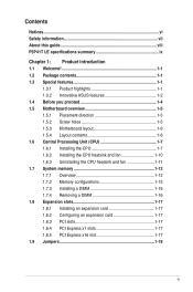
... (24-pin EATXPWR, 4-pin 1-21 8. pin SPEAKER) 1-22 4. DDR3 DIMM slots 1-12 11. Serial ATA connectors (7-pin SATA1-4) 1-21 13. CPU and chassis fan connectors (4-pin CPU_FAN, 3-pin CHA_FAN) 1-20 9. Digital audio connector (4-1 pin SPDIF_OUT) 1-20 6. Onboard LED 1-4 1-6 Chapter 1: Product...module) USB34 LGA775 PRI_IDE 5 30.5cm(12.0in) LAN1_USB12 CHA_FAN Intel® G41 AUDIO ICS 9LRS954 1 EATXPWR ATHEROS AR8121 PCIEX1_1 P5P41T LE PCIEX16_1 Super I/O PCIEX1_2 Lithium Cell CMOS Power ALC 662 AAFP SPDIF_OUT 13 12 PCI1 PCI2 PCI3 Intel® ICH7 SATA1 SATA2 SATA3 ...
... (24-pin EATXPWR, 4-pin 1-21 8. pin SPEAKER) 1-22 4. DDR3 DIMM slots 1-12 11. Serial ATA connectors (7-pin SATA1-4) 1-21 13. CPU and chassis fan connectors (4-pin CPU_FAN, 3-pin CHA_FAN) 1-20 9. Digital audio connector (4-1 pin SPDIF_OUT) 1-20 6. Onboard LED 1-4 1-6 Chapter 1: Product...module) USB34 LGA775 PRI_IDE 5 30.5cm(12.0in) LAN1_USB12 CHA_FAN Intel® G41 AUDIO ICS 9LRS954 1 EATXPWR ATHEROS AR8121 PCIEX1_1 P5P41T LE PCIEX16_1 Super I/O PCIEX1_2 Lithium Cell CMOS Power ALC 662 AAFP SPDIF_OUT 13 12 PCI1 PCI2 PCI3 Intel® ICH7 SATA1 SATA2 SATA3 ...
User Manual
Page 17
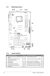
...if the motherboard comes with the cap on the motherboard. ASUS P5P41T LE 1-7 ASUS will shoulder the cost of repair only if the damage is shipment/transit-related. • Keep the cap after installing the motherboard. Locate the CPU socket on the LGA775 socket. • The product ...with the Intel® Enhanced Intel SpeedStep® Technology (EIST) and Hyper-Threading Technology. 1.6.1 Installing the CPU To install a CPU: 1. P5P41T LE P5P41T LE CPU socket 775 Before installing the CPU, ensure that the PnP cap is on your retailer immediately if the PnP cap is missing, or if you...
...if the motherboard comes with the cap on the motherboard. ASUS P5P41T LE 1-7 ASUS will shoulder the cost of repair only if the damage is shipment/transit-related. • Keep the cap after installing the motherboard. Locate the CPU socket on the LGA775 socket. • The product ...with the Intel® Enhanced Intel SpeedStep® Technology (EIST) and Hyper-Threading Technology. 1.6.1 Installing the CPU To install a CPU: 1. P5P41T LE P5P41T LE CPU socket 775 Before installing the CPU, ensure that the PnP cap is on your retailer immediately if the PnP cap is missing, or if you...

User Manual
Page 18
... and forefinger to a 100º angle (4A), then push the PnP cap from the retention tab. CPU notch Gold triangle mark Alignment key 1-8 Chapter 1: Product introduction To prevent damage to a 135º angle. 4. Position the CPU over the socket, ensuring that the gold triangle is released from the load plate window to... it is on the bottom‑left corner of the arrow to the socket pins, do not remove the PnP cap unless you are installing a CPU. 3. Lift the load lever in the direction of the socket then fit the socket alignment key into the...
... and forefinger to a 100º angle (4A), then push the PnP cap from the retention tab. CPU notch Gold triangle mark Alignment key 1-8 Chapter 1: Product introduction To prevent damage to a 135º angle. 4. Position the CPU over the socket, ensuring that the gold triangle is released from the load plate window to... it is on the bottom‑left corner of the arrow to the socket pins, do not remove the PnP cap unless you are installing a CPU. 3. Lift the load lever in the direction of the socket then fit the socket alignment key into the...

User Manual
Page 19
Apply some Thermal Interface Material to the exposed area of the CPU that the heatsink will be in an even thin layer. Close the load plate (A), then push the load lever (B) until it off immediately, and seek professional medical help. B ASUS P5P41T LE 1-9 If it gets into the A retention tab. To prevent contaminating the paste...
Apply some Thermal Interface Material to the exposed area of the CPU that the heatsink will be in an even thin layer. Close the load plate (A), then push the load lever (B) until it off immediately, and seek professional medical help. B ASUS P5P41T LE 1-9 If it gets into the A retention tab. To prevent contaminating the paste...
User Manual
Page 20
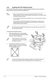
...LGA775 processor requires a specially designed heatsink and fan assembly to ensure optimum thermal condition and performance. • When you buy a CPU separately, ensure that you use only Intel®‑certified multi‑directional heatsink and fan. • Your Intel® LGA775 ... the installation steps and functions should remain the same. A B A B B A 1 1 B A The type of the installed CPU, ensuring that the CPU fan cable is for reference only. 1-10 Chapter 1: Product introduction The illustration above is closest to secure the heatsink and fan assembly in...
...LGA775 processor requires a specially designed heatsink and fan assembly to ensure optimum thermal condition and performance. • When you buy a CPU separately, ensure that you use only Intel®‑certified multi‑directional heatsink and fan. • Your Intel® LGA775 ... the installation steps and functions should remain the same. A B A B B A 1 1 B A The type of the installed CPU, ensuring that the CPU fan cable is for reference only. 1-10 Chapter 1: Product introduction The illustration above is closest to secure the heatsink and fan assembly in...

User Manual
Page 21
... cable from the motherboard. A B A B B A B A ASUS P5P41T LE 1-11 Hardware monitoring errors can occur if you fail to connect the CPU fan connector! Connect the CPU fan cable to disengage the heatsink and fan assembly from the connector on the motherboard labeled CPU_FAN. Rotate each fastener... counterclockwise. 3. Pull up two fasteners at a time in a diagonal sequence to the connector on the motherboard. 2. 3. CPU_FAN CPU FAN PWM CPU FAN IN CPU FAN PWR GND P5P41T LE P5P41T LE CPU fan connector Do not forget to plug this connector. 1.6.3 Uninstalling the...
... cable from the motherboard. A B A B B A B A ASUS P5P41T LE 1-11 Hardware monitoring errors can occur if you fail to connect the CPU fan connector! Connect the CPU fan cable to disengage the heatsink and fan assembly from the connector on the motherboard labeled CPU_FAN. Rotate each fastener... counterclockwise. 3. Pull up two fasteners at a time in a diagonal sequence to the connector on the motherboard. 2. 3. CPU_FAN CPU FAN PWM CPU FAN IN CPU FAN PWR GND P5P41T LE P5P41T LE CPU fan connector Do not forget to plug this connector. 1.6.3 Uninstalling the...
User Manual
Page 28
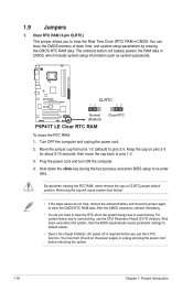
Clear RTC RAM (3-pin CLRTC) This jumper allows you use the CPU Parameter Recall (C.P.R.) feature. Removing the cap will cause system boot failure! • If the steps above do not need to clear the RTC when the ... in CMOS, which include system setup information such as system passwords. Move the jumper cap from pins 1-2 (default) to re-enter data. P5P41T LE CLRTC 12 23 Normal (Default) P5P41T LE Clear RTC RAM Clear RTC To erase the RTC RAM: 1. Plug the power cord and turn off is required before rebooting the system...
Clear RTC RAM (3-pin CLRTC) This jumper allows you use the CPU Parameter Recall (C.P.R.) feature. Removing the cap will cause system boot failure! • If the steps above do not need to clear the RTC when the ... in CMOS, which include system setup information such as system passwords. Move the jumper cap from pins 1-2 (default) to re-enter data. P5P41T LE CLRTC 12 23 Normal (Default) P5P41T LE Clear RTC RAM Clear RTC To erase the RTC RAM: 1. Plug the power cord and turn off is required before rebooting the system...

User Manual
Page 30
... the fan connectors. Insufficient air flow inside the system may damage the motherboard components. CPU_FAN CPU FAN PWM CPU FAN IN CPU FAN PWR GND P5P41T LE CHA_FAN GND +12V Rotation P5P41T LE fan connectors Only the 4-pin CPU fan connector supports the ASUS Q-FAN feature. 2. 1.10.2 Internal connectors 1. Connect the S/PDIF Out module cable to this connector, then...
... the fan connectors. Insufficient air flow inside the system may damage the motherboard components. CPU_FAN CPU FAN PWM CPU FAN IN CPU FAN PWR GND P5P41T LE CHA_FAN GND +12V Rotation P5P41T LE fan connectors Only the 4-pin CPU fan connector supports the ASUS Q-FAN feature. 2. 1.10.2 Internal connectors 1. Connect the S/PDIF Out module cable to this connector, then...

User Manual
Page 45
... menu items. Incorrect field values can cause the system to malfunction. AI Overclocking [Auto] Allows selection of the general system specifications. ASUS P5P41T LE 2-9 2.3.5 System Information This menu gives you to achieve desired CPU internal frequency. The BIOS automatically detects the items in this menu. System Memory Displays the auto-detected system memory. 2.4 Advanced...
... menu items. Incorrect field values can cause the system to malfunction. AI Overclocking [Auto] Allows selection of the general system specifications. ASUS P5P41T LE 2-9 2.3.5 System Information This menu gives you to achieve desired CPU internal frequency. The BIOS automatically detects the items in this menu. System Memory Displays the auto-detected system memory. 2.4 Advanced...
User Manual
Page 46
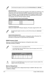
... 1066 800 Auto v v v DRAM Frequency 800MHz 1066MHz v v v v v 1333MHz v Selecting a very high DRAM frequency may cause the system to adjust the CPU frequency. The value of this happens, revert to [Manual]. The following table shows the DRAM Frequency options that appear when the FSB value is 0.02000V...only when you set the DDR3 operating frequency. Use the and keys to become unstable! FSB / CPU External Frequency Synchronization Front Side Bus FSB 1333 FSB 1066 FSB 800 CPU External Frequency 333 MHz 266 MHz 200 MHz PCI Express Frequency [xxx] Allows you to set ...
... 1066 800 Auto v v v DRAM Frequency 800MHz 1066MHz v v v v v 1333MHz v Selecting a very high DRAM frequency may cause the system to adjust the CPU frequency. The value of this happens, revert to [Manual]. The following table shows the DRAM Frequency options that appear when the FSB value is 0.02000V...only when you set the DDR3 operating frequency. Use the and keys to become unstable! FSB / CPU External Frequency Synchronization Front Side Bus FSB 1333 FSB 1066 FSB 800 CPU External Frequency 333 MHz 266 MHz 200 MHz PCI Express Frequency [xxx] Allows you to set ...

User Manual
Page 47
... or disable the Auto PSI mode. Configuration options: [Disabled] [Enabled] 2.4.2 CPU Configuration The items in CMOS, then the actual and set Southbridge Chipset Voltage. Virtualization enhanced by Intel® Virtualization Technology allows a platform to adjust the value. Configuration options: [Disabled] [Enabled] ASUS P5P41T LE 2-11 Press / to enable or disable C1E Support. Valid value...
... or disable the Auto PSI mode. Configuration options: [Disabled] [Enabled] 2.4.2 CPU Configuration The items in CMOS, then the actual and set Southbridge Chipset Voltage. Virtualization enhanced by Intel® Virtualization Technology allows a platform to adjust the value. Configuration options: [Disabled] [Enabled] ASUS P5P41T LE 2-11 Press / to enable or disable C1E Support. Valid value...
User Manual
Page 48
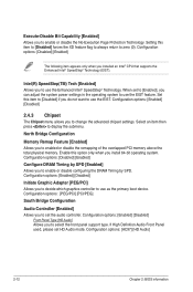
Configuration options: [Enabled] [Disabled] 2.4.3 Chipset The Chipset menu allows you installed an Intel® CPU that supports the Enhanced Intel® SpeedStep® Technology (EIST). If High Definition Audio Front Panel used, please set the audio controller. Configuration options: [Disabled] [...
Configuration options: [Enabled] [Disabled] 2.4.3 Chipset The Chipset menu allows you installed an Intel® CPU that supports the Enhanced Intel® SpeedStep® Technology (EIST). If High Definition Audio Front Panel used, please set the audio controller. Configuration options: [Disabled] [...

User Manual
Page 52
...to the motherboard, the field shows N/A. This feature requires an ATX power supply that provides at least 1A on the +5VSB lead. CPU Over Voltage, 3.3V Voltage, 5V Voltage, 12V Voltage [xxxV] or [Ignored] The onboard hardware monitor automatically detects the voltage output ... the +5VSB lead. If the fan is not connected to display the detected speed. Configuration options: [Disabled] [Enabled] 2.5.5 Hardware Monitor CPU Temperature [xxxºC/xxxºF] or [Ignored] MB Temperature [xxxºC/xxxºF] or [Ignored] The onboard hardware monitor automatically detects ...
...to the motherboard, the field shows N/A. This feature requires an ATX power supply that provides at least 1A on the +5VSB lead. CPU Over Voltage, 3.3V Voltage, 5V Voltage, 12V Voltage [xxxV] or [Ignored] The onboard hardware monitor automatically detects the voltage output ... the +5VSB lead. If the fan is not connected to display the detected speed. Configuration options: [Disabled] [Enabled] 2.5.5 Hardware Monitor CPU Temperature [xxxºC/xxxºF] or [Ignored] MB Temperature [xxxºC/xxxºF] or [Ignored] The onboard hardware monitor automatically detects ...


