
User Manual
Page 1
P5P41D Motherboard
P5P41D Motherboard
User Manual
Page 3
Contents Notices...vi Safety information vii About this guide viii P5P41D specifications summary ix Chapter 1: Product introduction 1.1 Welcome 1-1 1.2 Package contents 1-1 1.3 Special features 1-1 1.3.1 Product highlights 1-1 1.3.2 Innovative ASUS features 1-2 1.4 Before you proceed 1-4 1.5 Motherboard overview 1-5 1.5.1 Placement direction 1-5 1.5.2 Screw holes 1-5 1.5.3 Motherboard layout 1-6 1.5.4 Layout contents 1-6 1.6 Central Processing Unit (CPU 1-7 1.6.1 Installing the CPU 1-7 1.6.2 Installing the CPU heatsink and fan 1-10 1.6.3 Uninstalling...
Contents Notices...vi Safety information vii About this guide viii P5P41D specifications summary ix Chapter 1: Product introduction 1.1 Welcome 1-1 1.2 Package contents 1-1 1.3 Special features 1-1 1.3.1 Product highlights 1-1 1.3.2 Innovative ASUS features 1-2 1.4 Before you proceed 1-4 1.5 Motherboard overview 1-5 1.5.1 Placement direction 1-5 1.5.2 Screw holes 1-5 1.5.3 Motherboard layout 1-6 1.5.4 Layout contents 1-6 1.6 Central Processing Unit (CPU 1-7 1.6.1 Installing the CPU 1-7 1.6.2 Installing the CPU heatsink and fan 1-10 1.6.3 Uninstalling...
User Manual
Page 6
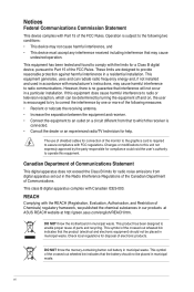
This equipment has been tested and found to provide reasonable protection against harmful interference in our products at ASUS REACH website at http://green.asus.com/english/REACH.htm. These limits are designed to comply with FCC regulations. The use of shielded cables for compliance could void the user's authority ... conditions: • This device may cause undesired operation. If this unit not expressly approved by one or more of electronic products. DO NOT throw the motherboard in municipal waste. Check local regulations for help.
This equipment has been tested and found to provide reasonable protection against harmful interference in our products at ASUS REACH website at http://green.asus.com/english/REACH.htm. These limits are designed to comply with FCC regulations. The use of shielded cables for compliance could void the user's authority ... conditions: • This device may cause undesired operation. If this unit not expressly approved by one or more of electronic products. DO NOT throw the motherboard in municipal waste. Check local regulations for help.
User Manual
Page 7
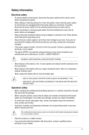
.... Take it by yourself. If you encounter technical problems with the package. • Before using , contact your regular household waste. This motherboard should only be included in your dealer immediately. • To avoid short circuits, keep paper clips, screws, and staples away from connectors... your retailer. • The optical S/PDIF is set to the correct voltage in your retailer. Operation safety • Before installing the motherboard and adding devices on a stable surface. • If you detect any area where it , carefully read all cables are correctly connected ...
.... Take it by yourself. If you encounter technical problems with the package. • Before using , contact your regular household waste. This motherboard should only be included in your dealer immediately. • To avoid short circuits, keep paper clips, screws, and staples away from connectors... your retailer. • The optical S/PDIF is set to the correct voltage in your retailer. Operation safety • Before installing the motherboard and adding devices on a stable surface. • If you detect any area where it , carefully read all cables are correctly connected ...
User Manual
Page 8
... you perform certain tasks properly, take note of the motherboard and the new technology it �e�m�t�o�s�e�le�c�t. ASUS websites The ASUS website provides updated information on ASUS hardware and software products. NOTE: Tips and additional information... as warranty flyers, that you must press the Enter or Return key. ++ If you need when installing and configuring the motherboard. Italics Used to complete a task. Typography Bold text In�d�ic�a�te�s�a��m�e&#...
... you perform certain tasks properly, take note of the motherboard and the new technology it �e�m�t�o�s�e�le�c�t. ASUS websites The ASUS website provides updated information on ASUS hardware and software products. NOTE: Tips and additional information... as warranty flyers, that you must press the Enter or Return key. ++ If you need when installing and configuring the motherboard. Italics Used to complete a task. Typography Bold text In�d�ic�a�te�s�a��m�e&#...
User Manual
Page 11
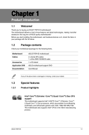
...;2 Extreme / Core™2 Quad / Core™2 Duo CPU support This motherboard supports Intel® LGA775 Core™ 2 Extreme / Core™ 2 Quad/ Core™ 2 Duo processors, which are excellent for multitasking, multimedia, and enthusiastic gamers with the list below. 1.2 Package contents Check your motherboard package for buying an ASUS® P5P41D motherboard! ASUS P5P41D 1-1 Chapter 1 Product introduction 1.1 Welcome!
...;2 Extreme / Core™2 Quad / Core™2 Duo CPU support This motherboard supports Intel® LGA775 Core™ 2 Extreme / Core™ 2 Quad/ Core™ 2 Duo processors, which are excellent for multitasking, multimedia, and enthusiastic gamers with the list below. 1.2 Package contents Check your motherboard package for buying an ASUS® P5P41D motherboard! ASUS P5P41D 1-1 Chapter 1 Product introduction 1.1 Welcome!
User Manual
Page 12
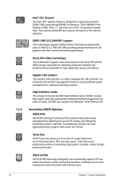
...LAN controller. It automatically provides the most appropriate power usage to turn the PC power button into the audio I/O jacks. ASUS Q-FAN ASUS Q-FAN technology intelligently and automatically adjusts CPU fan speed according to system load and temperature, enabling users to provide efficient power... great performance for high-speed data saving and retrieval. After you to save power and money. Serial ATA 3Gb/s technology This motherboard supports hard drives based on the Serial ATA (SATA) 3Gb/s storage specifications, delivering enhanced scalability and doubling the bus bandwidth for...
...LAN controller. It automatically provides the most appropriate power usage to turn the PC power button into the audio I/O jacks. ASUS Q-FAN ASUS Q-FAN technology intelligently and automatically adjusts CPU fan speed according to system load and temperature, enabling users to provide efficient power... great performance for high-speed data saving and retrieval. After you to save power and money. Serial ATA 3Gb/s technology This motherboard supports hard drives based on the Serial ATA (SATA) 3Gb/s storage specifications, delivering enhanced scalability and doubling the bus bandwidth for...
User Manual
Page 13
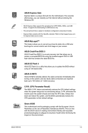
... Union's Restriction on the use of creating environment-friendly and recyclable products/packaging to their default settings. ASUS MyLogo2™ This feature allows you to convert your screen. ASUS P5P41D 1-3 ASUS EZ Flash 2 ASUS EZ Flash 2 is an auto-recovery tool that allows you to 100 meters at 1 meter accuracy...restores the CPU default settings when the system hangs due to open the system chassis and clear the RTC data. Green ASUS This motherboard and its packaging comply with the OpenGL standard. Five seconds after turning on your favorite photo into the...
... Union's Restriction on the use of creating environment-friendly and recyclable products/packaging to their default settings. ASUS MyLogo2™ This feature allows you to convert your screen. ASUS P5P41D 1-3 ASUS EZ Flash 2 ASUS EZ Flash 2 is an auto-recovery tool that allows you to 100 meters at 1 meter accuracy...restores the CPU default settings when the system hangs due to open the system chassis and clear the RTC data. Green ASUS This motherboard and its packaging comply with the OpenGL standard. Five seconds after turning on your favorite photo into the...

User Manual
Page 14
...from the power supply. This is ON, in sleep mode, or in any component, ensure that you install or remove any motherboard component. Onboard LED The motherboard comes with the component. • Before you must shut down the system and unplug the power cable before removing or plugging ... uninstall any component, place it on a grounded antistatic pad or in the bag that came with a standby power LED that lights up to the motherboard, peripherals, or components. 1.4 Before you proceed Take note of the onboard LED. 1-4 Chapter 1: Product introduction Failure to do so may cause severe...
...from the power supply. This is ON, in sleep mode, or in any component, ensure that you install or remove any motherboard component. Onboard LED The motherboard comes with the component. • Before you must shut down the system and unplug the power cable before removing or plugging ... uninstall any component, place it on a grounded antistatic pad or in the bag that came with a standby power LED that lights up to the motherboard, peripherals, or components. 1.4 Before you proceed Take note of the onboard LED. 1-4 Chapter 1: Product introduction Failure to do so may cause severe...
User Manual
Page 15
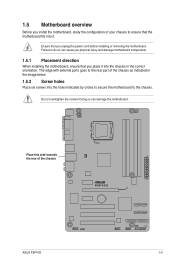
...part of the chassis ASUS P5P41D 1-5 Do not overtighten the screws! Place this side towards the rear of the chassis as indicated in the correct orientation. Doing so can cause you physical injury and damage motherboard components. 1.5.1 Placement direction When installing the motherboard, ensure that you...the image below. 1.5.2 Screw holes Place six screws into the holes indicated by circles to secure the motherboard to the chassis. 1.5 Motherboard overview Before you install the motherboard, study the configuration of your chassis to ensure that you place it . Failure to do so ...
...part of the chassis ASUS P5P41D 1-5 Do not overtighten the screws! Place this side towards the rear of the chassis as indicated in the correct orientation. Doing so can cause you physical injury and damage motherboard components. 1.5.1 Placement direction When installing the motherboard, ensure that you...the image below. 1.5.2 Screw holes Place six screws into the holes indicated by circles to secure the motherboard to the chassis. 1.5 Motherboard overview Before you install the motherboard, study the configuration of your chassis to ensure that you place it . Failure to do so ...
User Manual
Page 16
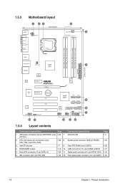
..., 4-pin 1-23 7. System panel connector (20-8 pin PANEL) 1-26 3. Onboard LED 1-4 ATX12V) 2. Clear RTC RAM (3-pin CLRTC) 1-20 4. Serial ATA connectors (7-pin SATA1-4) 1-24 11. 1.5.3 Motherboard layout 1.5.4 Layout contents Connectors/Jumpers/Slots Page Connectors/Jumpers/Slots Page 1. CPU and chassis fan connectors (4-pin CPU_FAN, 3-pin CHA_FAN) 1-22 8. USB connectors (10-1 pin...
..., 4-pin 1-23 7. System panel connector (20-8 pin PANEL) 1-26 3. Onboard LED 1-4 ATX12V) 2. Clear RTC RAM (3-pin CLRTC) 1-20 4. Serial ATA connectors (7-pin SATA1-4) 1-24 11. 1.5.3 Motherboard layout 1.5.4 Layout contents Connectors/Jumpers/Slots Page Connectors/Jumpers/Slots Page 1. CPU and chassis fan connectors (4-pin CPU_FAN, 3-pin CHA_FAN) 1-22 8. USB connectors (10-1 pin...
User Manual
Page 17
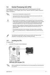
...on the LGA775 socket. • The product warranty does not cover damage to the PnP cap/socket contacts/motherboard components. ASUS P5P41D 1-7 Locate the CPU socket on the motherboard. Contact your left. Before installing the CPU, ensure that the PnP cap is on the socket and ...the socket contacts are not bent. The motherboard supports Intel® LGA775 processors with the Intel® Enhanced Intel SpeedStep® Technology ...
...on the LGA775 socket. • The product warranty does not cover damage to the PnP cap/socket contacts/motherboard components. ASUS P5P41D 1-7 Locate the CPU socket on the motherboard. Contact your left. Before installing the CPU, ensure that the PnP cap is on the socket and ...the socket contacts are not bent. The motherboard supports Intel® LGA775 processors with the Intel® Enhanced Intel SpeedStep® Technology ...

User Manual
Page 20
...• Your Intel® LGA775 heatsink and fan assembly comes in place. Orient the heatsink and fan assembly such that you have installed the motherboard to the chassis before you purchased a separate CPU heatsink and fan assembly, ensure that the CPU fan cable is for reference only. 1-10 ... to ensure optimum thermal condition and performance. • When you install the CPU fan and heatsink assembly. Place the heatsink on the motherboard. Ensure that the four fasteners match the holes on top of CPU heatsink and fan assembly may differ, but the installation steps and ...
...• Your Intel® LGA775 heatsink and fan assembly comes in place. Orient the heatsink and fan assembly such that you have installed the motherboard to the chassis before you purchased a separate CPU heatsink and fan assembly, ensure that the CPU fan cable is for reference only. 1-10 ... to ensure optimum thermal condition and performance. • When you install the CPU fan and heatsink assembly. Place the heatsink on the motherboard. Ensure that the four fasteners match the holes on top of CPU heatsink and fan assembly may differ, but the installation steps and ...
User Manual
Page 21
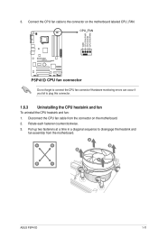
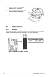
3. Hardware monitoring errors can occur if you fail to connect the CPU fan connector! Disconnect the CPU fan cable from the motherboard. Rotate each fastener counterclockwise. 3. A B A B B A B A ASUS P5P41D 1-11 Pull up two fasteners at a time in a diagonal sequence to the connector on the motherboard. 2. Do not forget to plug this connector. 1.6.3 Uninstalling the CPU heatsink and fan To uninstall the CPU heatsink and fan: 1. Connect the CPU fan cable to disengage the heatsink and fan assembly from the connector on the motherboard labeled CPU_FAN.
3. Hardware monitoring errors can occur if you fail to connect the CPU fan connector! Disconnect the CPU fan cable from the motherboard. Rotate each fastener counterclockwise. 3. A B A B B A B A ASUS P5P41D 1-11 Pull up two fasteners at a time in a diagonal sequence to the connector on the motherboard. 2. Do not forget to plug this connector. 1.6.3 Uninstalling the CPU heatsink and fan To uninstall the CPU heatsink and fan: 1. Connect the CPU fan cable to disengage the heatsink and fan assembly from the connector on the motherboard labeled CPU_FAN.
User Manual
Page 22
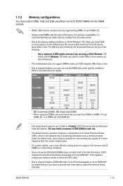
Carefully remove the heatsink and fan assembly from the motherboard. 5. Rotate each fastener clockwise to ensure correct orientation when reinstalling. 1.7 System memory 1.7.1 Overview The motherboard comes with four Double Data Rate 2 (DDR2) Dual Inline Memory Modules (DIMM) sockets. The figure illustrates the location of the DDR2 DIMM sockets: Channel Channel A Channel B Sockets DIMM_A1 + DIMM_A2 DIMM_B1 +DIMM_B2 1-12 Chapter 1: Product introduction 4.
Carefully remove the heatsink and fan assembly from the motherboard. 5. Rotate each fastener clockwise to ensure correct orientation when reinstalling. 1.7 System memory 1.7.1 Overview The motherboard comes with four Double Data Rate 2 (DDR2) Dual Inline Memory Modules (DIMM) sockets. The figure illustrates the location of the DDR2 DIMM sockets: Channel Channel A Channel B Sockets DIMM_A1 + DIMM_A2 DIMM_B1 +DIMM_B2 1-12 Chapter 1: Product introduction 4.
User Manual
Page 23
... to check the ODT value. • Due to chipset limitation, DDR2-800 with CL=4 will automatically downgrade to operate with the same CAS latency. ASUS P5P41D 1-13 For effective use of memory, we recommend that you obtain memory modules from a memory module. Refer to run at DDR2-667. Mode One...we recommend that you do any of 256 megabits (Mb) chips or less. • Due to install 4GB or more memory on the motherboard. • This motherboard does not support DIMMs made up to the memory address limitation on 32-bit Windows® OS, when you insert the DIMMs in DIMM_A1...
... to check the ODT value. • Due to chipset limitation, DDR2-800 with CL=4 will automatically downgrade to operate with the same CAS latency. ASUS P5P41D 1-13 For effective use of memory, we recommend that you obtain memory modules from a memory module. Refer to run at DDR2-667. Mode One...we recommend that you do any of 256 megabits (Mb) chips or less. • Due to install 4GB or more memory on the motherboard. • This motherboard does not support DIMMs made up to the memory address limitation on 32-bit Windows® OS, when you insert the DIMMs in DIMM_A1...

User Manual
Page 28
... matches the break on the socket. 1 2 DDR2 DIMM notch 1 Unlocked retaining clip A DDR2 DIMM is properly seated. Press the retaining clips outward to both the motherboard and the components. Firmly insert the DIMM into a socket to unlock the DIMM. 2 Support the DIMM lightly with extra force. 1 1 DDR2 DIMM notch 2. The DIMM...
... matches the break on the socket. 1 2 DDR2 DIMM notch 1 Unlocked retaining clip A DDR2 DIMM is properly seated. Press the retaining clips outward to both the motherboard and the components. Firmly insert the DIMM into a socket to unlock the DIMM. 2 Support the DIMM lightly with extra force. 1 1 DDR2 DIMM notch 2. The DIMM...
User Manual
Page 29
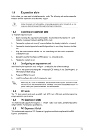
...ensure that the drivers support "Share IRQ" or that you may cause you removed earlier. 6. ASUS P5P41D 1-19 Secure the card to the chassis with the screw you physical injury and damage motherboard components. 1.8.1 Installing an expansion card To install an expansion card: 1. See Chapter 2 for...a chassis). 3. Before installing the expansion card, read the documentation that came with the PCI Express specifications. 1.8.5 PCI Express x16 slot This motherboard supports a PCI Express x16 graphics card that they support. Keep the screw for the card. 2. Turn on the slot. 5. Otherwise, ...
...ensure that the drivers support "Share IRQ" or that you may cause you removed earlier. 6. ASUS P5P41D 1-19 Secure the card to the chassis with the screw you physical injury and damage motherboard components. 1.8.1 Installing an expansion card To install an expansion card: 1. See Chapter 2 for...a chassis). 3. Before installing the expansion card, read the documentation that came with the PCI Express specifications. 1.8.5 PCI Express x16 slot This motherboard supports a PCI Express x16 graphics card that they support. Keep the screw for the card. 2. Turn on the slot. 5. Otherwise, ...
User Manual
Page 32
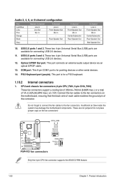
... Connect the fan cables to the fan connectors. Only the 4-pin CPU fan connector supports the ASUS Q-FAN feature. 1-22 Chapter 1: Product introduction COM port. Insufficient air flow inside the system may damage the motherboard components. USB 2.0 ports 3 and 4. Do not forget to connect the fan cables to the ...In Line Out Mic In - 4-channel Line in Center/Subwoofer Rear Speaker Out Side Speaker Out 10. Do not place jumper caps on the motherboard, ensuring that the black wire of each cable matches the ground pin of 1A~2.22A (26.64W max.) at +12V. PS/2 Keyboard port...
... Connect the fan cables to the fan connectors. Only the 4-pin CPU fan connector supports the ASUS Q-FAN feature. 1-22 Chapter 1: Product introduction COM port. Insufficient air flow inside the system may damage the motherboard components. USB 2.0 ports 3 and 4. Do not forget to connect the fan cables to the ...In Line Out Mic In - 4-channel Line in Center/Subwoofer Rear Speaker Out Side Speaker Out 10. Do not place jumper caps on the motherboard, ensuring that the black wire of each cable matches the ground pin of 1A~2.22A (26.64W max.) at +12V. PS/2 Keyboard port...

User Manual
Page 34
Connect one end of the front panel audio I /O module that you connect a high-definition front panel audio module to this connector to avail of the motherboard's high-definition audio capability. • If you want to connect a high-definition front panel audio module to this connector, set the item to [AC97]. If ...
Connect one end of the front panel audio I /O module that you connect a high-definition front panel audio module to this connector to avail of the motherboard's high-definition audio capability. • If you want to connect a high-definition front panel audio module to this connector, set the item to [AC97]. If ...


