User Manual
Page 4
Contents 1.11 Software support 1-29 1.11.1 Installing an operating system 1-29 1.11.2 Support DVD information 1-29 Chapter 2: BIOS information 2.1 Managing and updating your BIOS 2-1 2.1.1 ASUS Update utility 2-1 2.1.2 ASUS EZ Flash 2 2-2 2.1.3 ASUS CrashFree BIOS 2-3 2.2 BIOS setup program 2-4 2.2.1 BIOS menu screen 2-5 2.2.2 Menu bar 2-5 2.2.3 Navigation keys 2-6 2.2.4 Menu items 2-6 2.2.5 Submenu items 2-6 2.2.6 Configuration fields 2-6 2.2.7 Pop-up window 2-6 2.2.8 Scroll bar 2-6 2.2.9 General help 2-6 2.3 Main menu 2-7 2.3.1 System...
Contents 1.11 Software support 1-29 1.11.1 Installing an operating system 1-29 1.11.2 Support DVD information 1-29 Chapter 2: BIOS information 2.1 Managing and updating your BIOS 2-1 2.1.1 ASUS Update utility 2-1 2.1.2 ASUS EZ Flash 2 2-2 2.1.3 ASUS CrashFree BIOS 2-3 2.2 BIOS setup program 2-4 2.2.1 BIOS menu screen 2-5 2.2.2 Menu bar 2-5 2.2.3 Navigation keys 2-6 2.2.4 Menu items 2-6 2.2.5 Submenu items 2-6 2.2.6 Configuration fields 2-6 2.2.7 Pop-up window 2-6 2.2.8 Scroll bar 2-6 2.2.9 General help 2-6 2.3 Main menu 2-7 2.3.1 System...
User Manual
Page 7
...to fix it may become wet. • Place the product on it supports. • Chapter 2: BIOS information This chapter tells how to change system settings through the BIOS Setup menus. Do not place the product in your retailer. vii If possible, disconnect all power cables ...from connectors, slots, sockets and circuitry. • Avoid dust, humidity, and temperature extremes. If you are not sure about the voltage of the BIOS parameters are connected. Operation safety • Before installing the motherboard and adding devices on a stable surface. • If you add a device. ...
...to fix it may become wet. • Place the product on it supports. • Chapter 2: BIOS information This chapter tells how to change system settings through the BIOS Setup menus. Do not place the product in your retailer. vii If possible, disconnect all power cables ...from connectors, slots, sockets and circuitry. • Avoid dust, humidity, and temperature extremes. If you are not sure about the voltage of the BIOS parameters are connected. Operation safety • Before installing the motherboard and adding devices on a stable surface. • If you add a device. ...
User Manual
Page 10
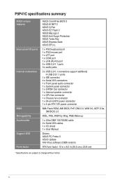
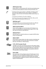
P5P41C specifications summary ASUS unique features Back panel I/O ports Internal connectors BIOS Manageability Accessories Support DVD Form factor ASUS CrashFree BIOS 3 ASUS AI NET 2 ASUS Q-Fan ASUS EZ Flash 2 ASUS MyLogo 2 ASUS Anti-Surge Protection ASUS Turbo Key ASUS Express Gate ASUS EPU-L 1 x PS/2 keyboard port 1 x PS/2 mouse port 1 x LPT port 1 x COM port 1 x LAN (RJ-45) port 4 x USB 2.0/1.1 ports 3 x audio jacks 2 x USB 2.0/1.1 connectors support...
P5P41C specifications summary ASUS unique features Back panel I/O ports Internal connectors BIOS Manageability Accessories Support DVD Form factor ASUS CrashFree BIOS 3 ASUS AI NET 2 ASUS Q-Fan ASUS EZ Flash 2 ASUS MyLogo 2 ASUS Anti-Surge Protection ASUS Turbo Key ASUS Express Gate ASUS EPU-L 1 x PS/2 keyboard port 1 x PS/2 mouse port 1 x LPT port 1 x COM port 1 x LAN (RJ-45) port 4 x USB 2.0/1.1 ports 3 x audio jacks 2 x USB 2.0/1.1 connectors support...
User Manual
Page 13
...and any faulty cable connections are reported back up to 100 meters at least 1.2GB free disk space. C.P.R. ASUS CrashFree BIOS 3 ASUS CrashFree BIOS 3 is a utility that allows you to convert your favorite photo into a 256-color boot logo for a ...at 1 meter accuracy. It supports file downloading to their default settings. eliminates the need to overclocking failure. ASUS EZ Flash 2 ASUS EZ Flash 2 is an auto-recovery tool that allows you instantly access the Internet and key applications before ... due to open the system chassis and clear the RTC data. ASUS P5P41C 1-3
...and any faulty cable connections are reported back up to 100 meters at least 1.2GB free disk space. C.P.R. ASUS CrashFree BIOS 3 ASUS CrashFree BIOS 3 is a utility that allows you to convert your favorite photo into a 256-color boot logo for a ...at 1 meter accuracy. It supports file downloading to their default settings. eliminates the need to overclocking failure. ASUS EZ Flash 2 ASUS EZ Flash 2 is an auto-recovery tool that allows you instantly access the Internet and key applications before ... due to open the system chassis and clear the RTC data. ASUS P5P41C 1-3
User Manual
Page 16
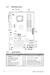
...) LGA775 USB34 CPU_FAN LAN1_USB12 CHA_FAN Intel® G41 30.5cm(12.0in) AUDIO EATXPWR ICS 9LRS954 1 AAFP RTL 8112L PCIEX1_1 P5P41C PCIEX16 Super I/O PCIEX1_2 Lithium Cell CMOS Power PCI1 ALC 887 SPDIF_OUT PCI2 PCI3 Intel® ICH7 SATA1 SATA2 5 SATA3 SATA4 PRI_IDE 8Mb... BIOS 6 CLRTC SB_PWR USB56 USB78 F_PANEL SPEAKER 7 13 12 11 10 9 8 1.5.4 Layout contents Connectors/Jumpers/Slots/LED 1. ATX power connectors (24-pin...
...) LGA775 USB34 CPU_FAN LAN1_USB12 CHA_FAN Intel® G41 30.5cm(12.0in) AUDIO EATXPWR ICS 9LRS954 1 AAFP RTL 8112L PCIEX1_1 P5P41C PCIEX16 Super I/O PCIEX1_2 Lithium Cell CMOS Power PCI1 ALC 887 SPDIF_OUT PCI2 PCI3 Intel® ICH7 SATA1 SATA2 5 SATA3 SATA4 PRI_IDE 8Mb... BIOS 6 CLRTC SB_PWR USB56 USB78 F_PANEL SPEAKER 7 13 12 11 10 9 8 1.5.4 Layout contents Connectors/Jumpers/Slots/LED 1. ATX power connectors (24-pin...
User Manual
Page 30
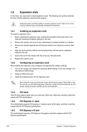
...To install an expansion card: 1. Keep the screw for the expansion card. When using PCI cards on the system and change the necessary BIOS settings, if any. The following sub‑sections describe the slots and the expansion cards that you intend to the chassis with the ... See Chapter 2 for the card. 2. Assign an IRQ to install expansion cards. Remove the system unit cover (if your motherboard is completely seated on BIOS setup. 2. Failure to do not need to the card. 3. Before installing the expansion card, read the documentation that the cards do so may need IRQ...
...To install an expansion card: 1. Keep the screw for the expansion card. When using PCI cards on the system and change the necessary BIOS settings, if any. The following sub‑sections describe the slots and the expansion cards that you intend to the chassis with the ... See Chapter 2 for the card. 2. Assign an IRQ to install expansion cards. Remove the system unit cover (if your motherboard is completely seated on BIOS setup. 2. Failure to do not need to the card. 3. Before installing the expansion card, read the documentation that the cards do so may need IRQ...
User Manual
Page 31
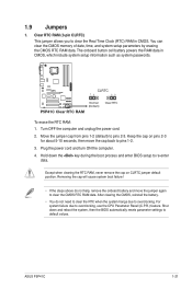
...above do not need to clear the RTC when the system hangs due to pins 1-2. 3. ASUS P5P41C 1-21 The onboard button cell battery powers the RAM data in CMOS. Hold down and reboot the system, then the BIOS automatically resets parameter settings to pins 2-3. Move the jumper cap from pins 1-2 (default) ...to default values. Shut down the key during the boot process and enter BIOS setup to clear the CMOS RTC RAM data. You can clear the CMOS memory of date, time, and system setup parameters by erasing the CMOS...
...above do not need to clear the RTC when the system hangs due to pins 1-2. 3. ASUS P5P41C 1-21 The onboard button cell battery powers the RAM data in CMOS. Hold down and reboot the system, then the BIOS automatically resets parameter settings to pins 2-3. Move the jumper cap from pins 1-2 (default) ...to default values. Shut down the key during the boot process and enter BIOS setup to clear the CMOS RTC RAM data. You can clear the CMOS memory of date, time, and system setup parameters by erasing the CMOS...
User Manual
Page 33
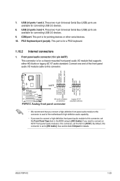
... connect a high-definition front panel audio module to this connector, set the Front Panel Type item in the BIOS setup to [AC97]. See section 2.4.3 Chipset for a PS/2 keyboard. 1.10.2 Internal connectors 1. USB 2.0... Keyboard port (purple). GND PRESENCE# SENSE1_RETUR SENSE2_RETUR AGND NC NC NC P5P41C AAFP PIN 1 PIN 1 MIC2 MICPWR Line out_R NC Line out_L PORT1 L PORT1 R PORT2 R SENSE_SEND ...PORT2 L HD-audio-compliant pin definition P5P41C Analog front panel connector Legacy AC'97 compliant definition • We recommend that you...
... connect a high-definition front panel audio module to this connector, set the Front Panel Type item in the BIOS setup to [AC97]. See section 2.4.3 Chipset for a PS/2 keyboard. 1.10.2 Internal connectors 1. USB 2.0... Keyboard port (purple). GND PRESENCE# SENSE1_RETUR SENSE2_RETUR AGND NC NC NC P5P41C AAFP PIN 1 PIN 1 MIC2 MICPWR Line out_R NC Line out_L PORT1 L PORT1 R PORT2 R SENSE_SEND ...PORT2 L HD-audio-compliant pin definition P5P41C Analog front panel connector Legacy AC'97 compliant definition • We recommend that you...
User Manual
Page 41
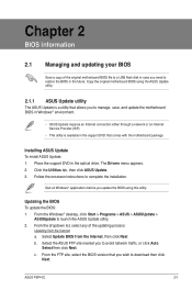
... Drivers menu appears. 2. Quit all Windows® applications before you to download then click Next. ASUS P5P41C 2-1 Follow the onscreen instructions to launch the ASUS Update utility. 2. Updating the BIOS To update the BIOS: 1. b. From the FTP site, select the BIOS version that comes with the motherboard package. From the dropdown list, select any of the...
... Drivers menu appears. 2. Quit all Windows® applications before you to download then click Next. ASUS P5P41C 2-1 Follow the onscreen instructions to launch the ASUS Update utility. 2. Updating the BIOS To update the BIOS: 1. b. From the FTP site, select the BIOS version that comes with the motherboard package. From the dropdown list, select any of the...
User Manual
Page 42
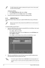
...ASUS EZ Flash 2 feature allows you start using EZ Flash 2: 1. Press to prevent system boot failure! 2-2 Chapter 2: BIOS information When the correct BIOS file is found . b. Updating from the Open window, then click Open. 3. Locate the BIOS file from a BIOS file a. ASUSTek EZ Flash 2 BIOS ROM Utility V3.36 FLASH TYPE: MXIC 25L8005 Current ROM BOARD: P5P41C...2 in any of updating itself through the Internet. Select Update BIOS from the ASUS website at www.asus.com. To update the BIOS using this utility, download the latest BIOS file from a file, then click Next. Go to the ...
...ASUS EZ Flash 2 feature allows you start using EZ Flash 2: 1. Press to prevent system boot failure! 2-2 Chapter 2: BIOS information When the correct BIOS file is found . b. Updating from the Open window, then click Open. 3. Locate the BIOS file from a BIOS file a. ASUSTek EZ Flash 2 BIOS ROM Utility V3.36 FLASH TYPE: MXIC 25L8005 Current ROM BOARD: P5P41C...2 in any of updating itself through the Internet. Select Update BIOS from the ASUS website at www.asus.com. To update the BIOS using this utility, download the latest BIOS file from a file, then click Next. Go to the ...
User Manual
Page 43
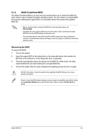
... the utility completes the updating process and turn on the system. 2. Refer to section 2.8 Exit menu for the BIOS file. ASUS P5P41C 2-3 Turn on again. Recovering the BIOS To recover the BIOS: 1. Ensure to load the BIOS default settings to restore the BIOS file when it fails or gets corrupted during the updating process. Download the latest...
... the utility completes the updating process and turn on the system. 2. Refer to section 2.8 Exit menu for the BIOS file. ASUS P5P41C 2-3 Turn on again. Recovering the BIOS To recover the BIOS: 1. Ensure to load the BIOS default settings to restore the BIOS file when it fails or gets corrupted during the updating process. Download the latest...

User Manual
Page 44
..., or the ++ keys to force reset from the operating system. • The default BIOS settings for this motherboard apply for this motherboard. 2-4 Chapter 2: BIOS information Entering BIOS Setup at startup To enter BIOS Setup at www.asus.com to download the latest BIOS file for most conditions to ensure optimum performance. If you see on . Select...
..., or the ++ keys to force reset from the operating system. • The default BIOS settings for this motherboard apply for this motherboard. 2-4 Chapter 2: BIOS information Entering BIOS Setup at startup To enter BIOS Setup at www.asus.com to download the latest BIOS file for most conditions to ensure optimum performance. If you see on . Select...

User Manual
Page 45
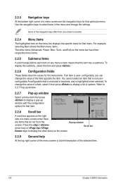
... selecting the exit options and loading default settings. Boot For changing the system boot configuration. 2.2.1 BIOS menu screen Menu items Menu bar Main Advanced Power Configuration fields BIOS SETUP UTILITY Boot Tools Exit General help System Time [00:31:48] System Date [Tue 01...has the following main items: Main For changing the basic system configuration. Power For changing the advanced power management (APM) configuration. ASUS P5P41C 2-5 Change Field Tab Select Field F1 General Help F10 Save and Exit ESC Exit v02.61 (C)Copyright 1985-2009, American Megatrends,...
... selecting the exit options and loading default settings. Boot For changing the system boot configuration. 2.2.1 BIOS menu screen Menu items Menu bar Main Advanced Power Configuration fields BIOS SETUP UTILITY Boot Tools Exit General help System Time [00:31:48] System Date [Tue 01...has the following main items: Main For changing the basic system configuration. Power For changing the advanced power management (APM) configuration. ASUS P5P41C 2-5 Change Field Tab Select Field F1 General Help F10 Save and Exit ESC Exit v02.61 (C)Copyright 1985-2009, American Megatrends,...
User Manual
Page 46
... These fields show the values for the menu items. If an item is a brief description of the selected item. 2-6 Chapter 2: BIOS information You cannot select an item that menu. Main Advanced BIOS SETUP UTILITY Power Boot Tools Exit Suspend Mode ACPI 2.0 Support ACPI APIC support APM Configuration Hardware Monitor [Auto] [Disabled] [EDniOsapabtbilloendesd...
... These fields show the values for the menu items. If an item is a brief description of the selected item. 2-6 Chapter 2: BIOS information You cannot select an item that menu. Main Advanced BIOS SETUP UTILITY Power Boot Tools Exit Suspend Mode ACPI 2.0 Support ACPI APIC support APM Configuration Hardware Monitor [Auto] [Disabled] [EDniOsapabtbilloendesd...

User Manual
Page 47
... for each IDE/SATA device. The BIOS automatically detects the values opposite the dimmed items (Device, Vendor, Size, LBA Mode, Block Mode, PIO Mode, Async DMA, Ultra DMA, and SMART monitoring). Select ARMD (ATAPI Removable Media Device) if your device is installed in the system. ASUS P5P41C 2-7 These values are specifically configuring a CD...
... for each IDE/SATA device. The BIOS automatically detects the values opposite the dimmed items (Device, Vendor, Size, LBA Mode, Block Mode, PIO Mode, Async DMA, Ultra DMA, and SMART monitoring). Select ARMD (ATAPI Removable Media Device) if your device is installed in the system. ASUS P5P41C 2-7 These values are specifically configuring a CD...

User Manual
Page 48
... to the device occurs one sector at a time if the device supports multi-sector transfer feature. Configuration options: [0] [5] [10] [15] [20] [25] [30] [35] 2-8 Chapter 2: BIOS information Configuration options: [Auto] [0] [1] [2] [3] [4] DMA Mode [Auto] Selects the DMA mode. LBA/Large Mode [Auto] Enables or disables the LBA mode. When set to [Auto...
... to the device occurs one sector at a time if the device supports multi-sector transfer feature. Configuration options: [0] [5] [10] [15] [20] [25] [30] [35] 2-8 Chapter 2: BIOS information Configuration options: [Auto] [0] [1] [2] [3] [4] DMA Mode [Auto] Selects the DMA mode. LBA/Large Mode [Auto] Enables or disables the LBA mode. When set to [Auto...
User Manual
Page 49
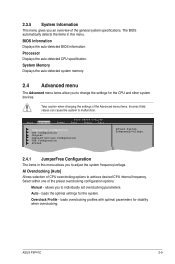
... system devices. Overclock Profile - ASUS P5P41C 2-9 Select either one of CPU overclocking options to achieve desired CPU internal frequency. loads overclocking profiles with optimal parameters for the system. BIOS Information Displays the auto-detected BIOS information. AI Overclocking [Auto].... 2.4 Advanced menu The Advanced menu items allow you to adjust the system frequency/voltage. Main Advanced Power BIOS SETUP UTILITY Boot Tools Exit JumperFree Configuration CPU Configuration Chipset Onboard Devices Configuration USB Configuration PCIPnP Adjust System frequency/...
... system devices. Overclock Profile - ASUS P5P41C 2-9 Select either one of CPU overclocking options to achieve desired CPU internal frequency. loads overclocking profiles with optimal parameters for the system. BIOS Information Displays the auto-detected BIOS information. AI Overclocking [Auto].... 2.4 Advanced menu The Advanced menu items allow you to adjust the system frequency/voltage. Main Advanced Power BIOS SETUP UTILITY Boot Tools Exit JumperFree Configuration CPU Configuration Chipset Onboard Devices Configuration USB Configuration PCIPnP Adjust System frequency/...

User Manual
Page 50
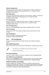
... the table below for the correct Front Side Bus and CPU External Frequency settings. The values range from 200 to the default setting. 2-10 Chapter 2: BIOS information Configuration options: [Auto] [90] [91] [92]~[150] The following two items appear only when you set the AI Overclocking item to [MANUAL]. If this... 800. The following item appears only when you set the AI Overclocking item to [Overclock Profile]. CPU Frequency [xxx] Displays the frequency sent by the BIOS.
... the table below for the correct Front Side Bus and CPU External Frequency settings. The values range from 200 to the default setting. 2-10 Chapter 2: BIOS information Configuration options: [Auto] [90] [91] [92]~[150] The following two items appear only when you set the AI Overclocking item to [MANUAL]. If this... 800. The following item appears only when you set the AI Overclocking item to [Overclock Profile]. CPU Frequency [xxx] Displays the frequency sent by the BIOS.
User Manual
Page 51
...] Setting this menu show the CPU-related information that the BIOS automatically detects. Virtualization enhanced by Intel® Virtualization Technology allows a platform to adjust the voltage. With virtualization, one computer system can function as multiple virtual systems. Configuration options: [Enabled] [Disabled] ASUS P5P41C 2-11 Key in the value directly or use +/- to run...
...] Setting this menu show the CPU-related information that the BIOS automatically detects. Virtualization enhanced by Intel® Virtualization Technology allows a platform to adjust the voltage. With virtualization, one computer system can function as multiple virtual systems. Configuration options: [Enabled] [Disabled] ASUS P5P41C 2-11 Key in the value directly or use +/- to run...
User Manual
Page 52
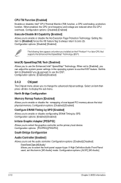
... enable or disable configurating DRAM Timing by SPD [Enabled] Allows you do not want to use the EIST. Configuration options: [AC97] [HD Audio] 2-12 Chapter 2: BIOS information When enabled, the CPU core frequency and voltage are reduced when the CPU overheats. When set this item to zero (0). Set this item to...
... enable or disable configurating DRAM Timing by SPD [Enabled] Allows you do not want to use the EIST. Configuration options: [AC97] [HD Audio] 2-12 Chapter 2: BIOS information When enabled, the CPU core frequency and voltage are reduced when the CPU overheats. When set this item to zero (0). Set this item to...


