User Manual
Page 4
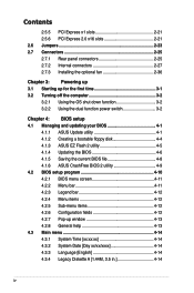
... 2-21 2.6 Jumpers 2-23 2.7 Connectors 2-25 2.7.1 Rear panel connectors 2-25 2.7.2 Internal connectors 2-27 2.7.3 Installing the optional fan 2-36 Chapter 3: Powering up 3.1 Starting up for the first time 3-1 3.2 Turning off the computer 3-2 3.2.1 Using the OS shut down function 3-2 3.2.2 Using the dual function power switch 3-2 Chapter 4: BIOS setup 4.1 Managing and updating your BIOS 4-1 4.1.1 ASUS Update utility 4-1 4.1.2 Creating a bootable...
... 2-21 2.6 Jumpers 2-23 2.7 Connectors 2-25 2.7.1 Rear panel connectors 2-25 2.7.2 Internal connectors 2-27 2.7.3 Installing the optional fan 2-36 Chapter 3: Powering up 3.1 Starting up for the first time 3-1 3.2 Turning off the computer 3-2 3.2.1 Using the OS shut down function 3-2 3.2.2 Using the dual function power switch 3-2 Chapter 4: BIOS setup 4.1 Managing and updating your BIOS 4-1 4.1.1 ASUS Update utility 4-1 4.1.2 Creating a bootable...
User Manual
Page 11
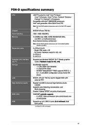
...ECC, un-buffered memory Dual channel memory architecture Note: Visit the ASUS website at mid-board; one at www.asus.com for the latest Qualified Vendors List (QVL). 2 x PCIe 2.0 x16 - P5N-D specifications summary CPU Chipset Front Side Bus Memory Expansion slots Scalable ... Optical S/PDIF out ports at back panel VIA6308P��c�o�n�t�r�o�l�le�r��s�u�p��p�o�r�t�s�: - 2 x IEEE 1394a connectors (one at www.asus.com for the Intel® CPU...
...ECC, un-buffered memory Dual channel memory architecture Note: Visit the ASUS website at mid-board; one at www.asus.com for the latest Qualified Vendors List (QVL). 2 x PCIe 2.0 x16 - P5N-D specifications summary CPU Chipset Front Side Bus Memory Expansion slots Scalable ... Optical S/PDIF out ports at back panel VIA6308P��c�o�n�t�r�o�l�le�r��s�u�p��p�o�r�t�s�: - 2 x IEEE 1394a connectors (one at www.asus.com for the Intel® CPU...

User Manual
Page 13
... I/O 1 x Floppy disk drive connector 1 x IDE connector 4 x Serial ATA connectors 2 x USB connectors support additional 4 USB ports 1 x IEEE 1394a port connector 1 x CPU / 1 x Power / 2 x Chassis Fan connectors Front panel audio connector 1 x S/PDIF Out Header Chassis Intrusion connector CD audio in 24-pin ATX Power connector 4-pin ATX 12V Power connector System Panel (Q-Connector) 8 Mb Flash ROM, AWARD BIOS, PnP, DMI2.0, WfM2.0, SM BIOS 2.4, ASUS EZ Flash 2, ASUS CrashFree BIOS 2 WfM...
... I/O 1 x Floppy disk drive connector 1 x IDE connector 4 x Serial ATA connectors 2 x USB connectors support additional 4 USB ports 1 x IEEE 1394a port connector 1 x CPU / 1 x Power / 2 x Chassis Fan connectors Front panel audio connector 1 x S/PDIF Out Header Chassis Intrusion connector CD audio in 24-pin ATX Power connector 4-pin ATX 12V Power connector System Panel (Q-Connector) 8 Mb Flash ROM, AWARD BIOS, PnP, DMI2.0, WfM2.0, SM BIOS 2.4, ASUS EZ Flash 2, ASUS CrashFree BIOS 2 WfM...
User Manual
Page 17
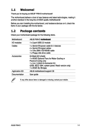
... disk drive cable Q-Shield (I/O shield) 1 x ASUS Optional Fans for buying an ASUS® P5N-D motherboard! Thank you start installing the motherboard, and hardware devices on it another standout in the long line of new features and latest technologies, making it , check the items in -1 ASUS Q-Connector Kit (USB, IEEE 1394, system panel; Before you for Water-Cooling or...
... disk drive cable Q-Shield (I/O shield) 1 x ASUS Optional Fans for buying an ASUS® P5N-D motherboard! Thank you start installing the motherboard, and hardware devices on it another standout in the long line of new features and latest technologies, making it , check the items in -1 ASUS Q-Connector Kit (USB, IEEE 1394, system panel; Before you for Water-Cooling or...
User Manual
Page 21
...The motherboard features the ASUS O.C. See page 4-40 for details. ASUS CrashFree BIOS 2 This feature allows you to easily connect or disconnect the chassis front panel cables to buy a replacement ROM chip. This protection eliminates the need to the motherboard. ASUS Q-Connector ASUS Q-Connector allows...a separate file, giving users freedom to share and distribute their favorite settings. ASUS Q-Shield The specially designed ASUS Q-Shield provides conductivity to install. ASUS P5N-D 1-5 ASUS Q-Fan2 technology intelligently adjusts both CPU fan and chassis fan speeds according to ...
...The motherboard features the ASUS O.C. See page 4-40 for details. ASUS CrashFree BIOS 2 This feature allows you to easily connect or disconnect the chassis front panel cables to buy a replacement ROM chip. This protection eliminates the need to the motherboard. ASUS Q-Connector ASUS Q-Connector allows...a separate file, giving users freedom to share and distribute their favorite settings. ASUS Q-Shield The specially designed ASUS Q-Shield provides conductivity to install. ASUS P5N-D 1-5 ASUS Q-Fan2 technology intelligently adjusts both CPU fan and chassis fan speeds according to ...
User Manual
Page 27
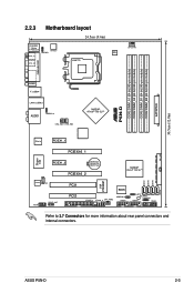
ASUS P5N-D 2-3 ® P5N-D DDR2 DIMM_A1 (64 bit,240-pin module) DDR2 DIMM_A2 (64 bit,240-pin module) DDR2 DIMM_B1 (64 bit,240-pin module) DDR2 DIMM_B2 (64 bit,240-pin module) EATXPWR 30.5cm (12.0in) 2.2.3 Motherboard layout 24.5cm (9.6in) PS/2KBMS T: Mouse B: Keyboard SPDIF_O1 ATX12V KBPWR SPDIF_O2 LGA775 EPU...174; nForce® 750i SLI™ ALC883 CD AAFP SPDIF_OUT PCI1 PCI2 BIOS FLOPPY IE1394_2 CHA_FAN2 USBPW5-8 USB56 CLRTC SB_PWR CHASSIS USB78 PANEL VIA VT6308P SATA1 SATA2 SATA3 SATA4 Refer to 2.7 Connectors for more information about rear panel connectors and internal...
ASUS P5N-D 2-3 ® P5N-D DDR2 DIMM_A1 (64 bit,240-pin module) DDR2 DIMM_A2 (64 bit,240-pin module) DDR2 DIMM_B1 (64 bit,240-pin module) DDR2 DIMM_B2 (64 bit,240-pin module) EATXPWR 30.5cm (12.0in) 2.2.3 Motherboard layout 24.5cm (9.6in) PS/2KBMS T: Mouse B: Keyboard SPDIF_O1 ATX12V KBPWR SPDIF_O2 LGA775 EPU...174; nForce® 750i SLI™ ALC883 CD AAFP SPDIF_OUT PCI1 PCI2 BIOS FLOPPY IE1394_2 CHA_FAN2 USBPW5-8 USB56 CLRTC SB_PWR CHASSIS USB78 PANEL VIA VT6308P SATA1 SATA2 SATA3 SATA4 Refer to 2.7 Connectors for more information about rear panel connectors and internal...

User Manual
Page 28
Keyboard power (3-pin KBPWR) Rear panel connectors 1. Line Out port (lime) 9. USB 2.0 ports 1 and 2 12. USB device wake-up (3-pin USBPW1-4, USBPW5-8) 3. USB 2.0 ports 3 and 4 13. Clear RTC RAM (3-pin CLRTC) 2. Rear ...
Keyboard power (3-pin KBPWR) Rear panel connectors 1. Line Out port (lime) 9. USB 2.0 ports 1 and 2 12. USB device wake-up (3-pin USBPW1-4, USBPW5-8) 3. USB 2.0 ports 3 and 4 13. Clear RTC RAM (3-pin CLRTC) 2. Rear ...

User Manual
Page 49
... port connects the rear speakers in a 4-channel, 6-channel, or 8-channel audio configuration.. 7. Line In port (light blue). Rear Speaker Out port (black). ASUS P5N-D 2-25 IEEE 1394a port. Refer to a Local Area Network (LAN) through a network hub. Line Out port (lime). Center/Subwoofer port (orange). In ... connection LAN port 5. This port is for audio/video devices, storage peripherals, PCs, or portable devices. 4. Parallel port. 2.7 Connectors 2.7.1 1 Rear panel connectors 2 3 4 56 78 16 15 14 13 12 11 10 9 1. This port connects a headphone or a speaker.
... port connects the rear speakers in a 4-channel, 6-channel, or 8-channel audio configuration.. 7. Line In port (light blue). Rear Speaker Out port (black). ASUS P5N-D 2-25 IEEE 1394a port. Refer to a Local Area Network (LAN) through a network hub. Line Out port (lime). Center/Subwoofer port (orange). In ... connection LAN port 5. This port is for audio/video devices, storage peripherals, PCs, or portable devices. 4. Parallel port. 2.7 Connectors 2.7.1 1 Rear panel connectors 2 3 4 56 78 16 15 14 13 12 11 10 9 1. This port connects a headphone or a speaker.
User Manual
Page 57
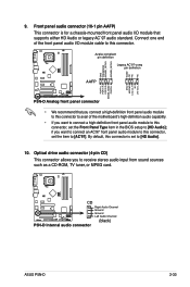
...) ASUS P5N-D 2-33 Azalia-compliant pin definition Legacy AC'97-compliant pin definition AAFP P5N-D Analog front panel connector • We recommend that supports either HD Audio or legacy AC`97 audio standard. Connect one end of the front panel audio I /O module that you connect a high-definition front panel audio module to this connector to avail of the motherboard...
...) ASUS P5N-D 2-33 Azalia-compliant pin definition Legacy AC'97-compliant pin definition AAFP P5N-D Analog front panel connector • We recommend that supports either HD Audio or legacy AC`97 audio standard. Connect one end of the front panel audio I /O module that you connect a high-definition front panel audio module to this connector to avail of the motherboard...

User Manual
Page 58
... warning speaker. PWR Ground Reset Ground 11. P5N-D System panel connector • System power LED (2-pin PLED) This 2-pin connector is for the chassis-mounted reset button for the system power LED. PLED SPEAKER PANEL IDE_LED RESET PWRSW * Requires an ATX power supply. PLED+ PLED+5V Ground Ground Speaker ® P5N-D IDE_LED+ IDE_LED- Pressing the power switch...
... warning speaker. PWR Ground Reset Ground 11. P5N-D System panel connector • System power LED (2-pin PLED) This 2-pin connector is for the chassis-mounted reset button for the system power LED. PLED SPEAKER PANEL IDE_LED RESET PWRSW * Requires an ATX power supply. PLED+ PLED+5V Ground Ground Speaker ® P5N-D IDE_LED+ IDE_LED- Pressing the power switch...
User Manual
Page 59
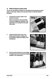
ASUS P5N-D 2-35 ASUS Q-Connector (system panel) You can use the ASUS Q-Connector to the ASUS Q-Connector. The front panel functions are now enabled. The figure shows the Q-Connector properly installed on the motherboard. 3. Connect the front panel cables to connect/disconnect chassis front panel cables in a few steps. Refer to the labels on the Q-Connector to know the detailed pin definitions, then match them to...
ASUS P5N-D 2-35 ASUS Q-Connector (system panel) You can use the ASUS Q-Connector to the ASUS Q-Connector. The front panel functions are now enabled. The figure shows the Q-Connector properly installed on the motherboard. 3. Connect the front panel cables to connect/disconnect chassis front panel cables in a few steps. Refer to the labels on the Q-Connector to know the detailed pin definitions, then match them to...

User Manual
Page 63
...ATX power button. Connect the power cord to a power outlet that all the connections, replace the system case cover. 2. Monitor b. For systems with the last device on the screen. While the tests are off. 3. ASUS...�P�5�N��-D� 3-1 Be sure that is equipped with "green" standards or if it has a "power standby" feature, the monitor LED may have failed a power-on , hold down the key to enter the BIOS Setup. Connect the power cord to the power connector...the system front panel case lights up. System power 6. At power on test. After ...
...ATX power button. Connect the power cord to a power outlet that all the connections, replace the system case cover. 2. Monitor b. For systems with the last device on the screen. While the tests are off. 3. ASUS...�P�5�N��-D� 3-1 Be sure that is equipped with "green" standards or if it has a "power standby" feature, the monitor LED may have failed a power-on , hold down the key to enter the BIOS Setup. Connect the power cord to the power connector...the system front panel case lights up. System power 6. At power on test. After ...
User Manual
Page 94
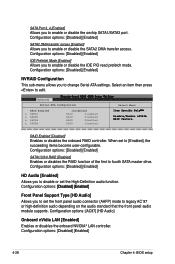
... an item then press to legacy AC`97 or high-definition audio depending on the audio standard that the front panel audio module supports. Configuration options: �[D��is�a��b�le��d�]�[�...Enabled] Allows you to change Serial ATA settings. Configuration options: [Disabled] [Enabled] 4-28 Chapter 4: BIOS setup When set the front panel audio connector (AAFP) mode to edit. Configuration options: [Disabled] [Enabled] NVRAID Configuration This sub-menu allows you to [Enabled], the succeeding items...
... an item then press to legacy AC`97 or high-definition audio depending on the audio standard that the front panel audio module supports. Configuration options: �[D��is�a��b�le��d�]�[�...Enabled] Allows you to change Serial ATA settings. Configuration options: [Disabled] [Enabled] 4-28 Chapter 4: BIOS setup When set the front panel audio connector (AAFP) mode to edit. Configuration options: [Disabled] [Enabled] NVRAID Configuration This sub-menu allows you to [Enabled], the succeeding items...


