
User Manual
Page 26
Clear RTC RAM (3-pin CLRTC) 2-21 2. Coaxial S/PDIF Out port 10. Serial port (COM1) 11. 2.2.4 Layout contents Slots Page 1. Parallel port 3. LAN (RJ-45) port 4. USB 2.0 ports 1 and 2 8. ...
Clear RTC RAM (3-pin CLRTC) 2-21 2. Coaxial S/PDIF Out port 10. Serial port (COM1) 11. 2.2.4 Layout contents Slots Page 1. Parallel port 3. LAN (RJ-45) port 4. USB 2.0 ports 1 and 2 8. ...
User Manual
Page 43
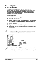
...values. To erase the RTC RAM: 1. Remove the onboard battery. 3. P5LD2-X/1333 CLRTC 12 23 Normal (Default) P5LD2-X/1333.Clear.RTC.RAM Clear RTC You do not need to clear the RTC when the system hangs due to pins 2-3. The onboard button cell battery powers the RAM data in CMOS. Move ...Plug the power cord and turn ON the computer. 6. For system failure due to clear the Real Time Clock (RTC) RAM in CMOS, which include system setup information such as system passwords. Shut down the key during the boot process and enter BIOS setup to pins 1-2. 4. ASUS P5LD2-X/1333 2-21
...values. To erase the RTC RAM: 1. Remove the onboard battery. 3. P5LD2-X/1333 CLRTC 12 23 Normal (Default) P5LD2-X/1333.Clear.RTC.RAM Clear RTC You do not need to clear the RTC when the system hangs due to pins 2-3. The onboard button cell battery powers the RAM data in CMOS. Move ...Plug the power cord and turn ON the computer. 6. For system failure due to clear the Real Time Clock (RTC) RAM in CMOS, which include system setup information such as system passwords. Shut down the key during the boot process and enter BIOS setup to pins 1-2. 4. ASUS P5LD2-X/1333 2-21
User Manual
Page 69
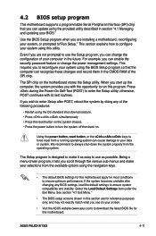
... to reconfigure your system using the BIOS Setup program so that you are for this program. ASUS P5LD2-X/1333 4-11 For example, you see on your screen. • Visit the ASUS website (www.asus.com) to run this motherboard. otherwise, POST continues with the opportunity to download the latest ... This motherboard supports a programmable Serial Peripheral Interface (SPI) chip that the computer can recognize these changes and record them in the CMOS RAM of the SPI chip. Use the BIOS Setup program when you can update using the navigation keys. • The default BIOS settings for...
... to reconfigure your system using the BIOS Setup program so that you are for this program. ASUS P5LD2-X/1333 4-11 For example, you see on your screen. • Visit the ASUS website (www.asus.com) to run this motherboard. otherwise, POST continues with the opportunity to download the latest ... This motherboard supports a programmable Serial Peripheral Interface (SPI) chip that the computer can recognize these changes and record them in the CMOS RAM of the SPI chip. Use the BIOS Setup program when you can update using the navigation keys. • The default BIOS settings for...
User Manual
Page 91
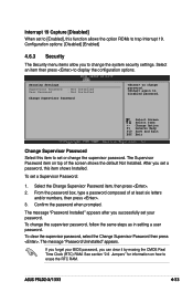
... Password item on how to disabled password. To clear the supervisor password, select the Change Supervisor Password then press . ASUS P5LD2-X/1333 4-33 Security Settings Supervisor Password User Password : Not Installed : Not Installed Change Supervisor Password to change the supervisor password...Supervisor Password: 1. If you forget your password. After you can clear it by erasing the CMOS Real Time Clock (RTC) RAM. Change Option F1 General Help F10 Save and Exit ESC Exit Change Supervisor Password Select this function allows the option ROMs to display...
... Password item on how to disabled password. To clear the supervisor password, select the Change Supervisor Password then press . ASUS P5LD2-X/1333 4-33 Security Settings Supervisor Password User Password : Not Installed : Not Installed Change Supervisor Password to change the supervisor password...Supervisor Password: 1. If you forget your password. After you can clear it by erasing the CMOS Real Time Clock (RTC) RAM. Change Option F1 General Help F10 Save and Exit ESC Exit Change Supervisor Password Select this function allows the option ROMs to display...

User Manual
Page 94
... Exit system setup after saving the changes. If you made and restore the previously saved values. An onboard backup battery sustains the CMOS RAM so it stays on even when the computer is turned off. Select to save the changes while exiting. If you attempt to exit ...values you selected are finished making your selections, choose this option, a confirmation window appears. Exit & Save Changes Once you are saved to the CMOS RAM. When you select this option from this option, a confirmation appears. F10 key can be used for this operation. 4.7 Exit menu The Exit menu ...
... Exit system setup after saving the changes. If you made and restore the previously saved values. An onboard backup battery sustains the CMOS RAM so it stays on even when the computer is turned off. Select to save the changes while exiting. If you attempt to exit ...values you selected are finished making your selections, choose this option, a confirmation window appears. Exit & Save Changes Once you are saved to the CMOS RAM. When you select this option from this option, a confirmation appears. F10 key can be used for this operation. 4.7 Exit menu The Exit menu ...

User Manual
Page 95
Load Setup Defaults Allows you press , a confirmation window appears. Select to the non-volatile RAM.‑ ASUS P5LD2-X/1333 4-37 When you select this option or if you to load the default values for each of the parameters on the Setup menus. Select Exit & Save Changes or make other changes before saving the values to load the default values.
Load Setup Defaults Allows you press , a confirmation window appears. Select to the non-volatile RAM.‑ ASUS P5LD2-X/1333 4-37 When you select this option or if you to load the default values for each of the parameters on the Setup menus. Select Exit & Save Changes or make other changes before saving the values to load the default values.


