P5LD2-VM User's Manual for English Edition
Page 5
... menu 2-34 2.6.1 Boot Device Priority 2-34 2.6.2 Boot Settings Configuration 2-35 2.6.3 Security 2-36 2.7 Exit menu 2-38 Chapter 3: Software support 3.1 Installing an operating system 3-2 3.2 Support CD information 3-2 3.2.1 Running the support CD 3-2 3.2.2 Drivers menu 3-3 3.2.3 Utilities menu 3-4 3.2.4 Manuals menu 3-5 3.2.5 ASUS Contact information 3-6 Appendix: CPU features A.1 Intel® EM64T A-2 Using the Intel® EM64T feature A-2 A.2 Enhanced Intel SpeedStep®...
... menu 2-34 2.6.1 Boot Device Priority 2-34 2.6.2 Boot Settings Configuration 2-35 2.6.3 Security 2-36 2.7 Exit menu 2-38 Chapter 3: Software support 3.1 Installing an operating system 3-2 3.2 Support CD information 3-2 3.2.1 Running the support CD 3-2 3.2.2 Drivers menu 3-3 3.2.3 Utilities menu 3-4 3.2.4 Manuals menu 3-5 3.2.5 ASUS Contact information 3-6 Appendix: CPU features A.1 Intel® EM64T A-2 Using the Intel® EM64T feature A-2 A.2 Enhanced Intel SpeedStep®...
P5LD2-VM User's Manual for English Edition
Page 8
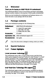
... includes description of the standard package. Detailed descriptions of the BIOS parameters are not part of the jumpers and connectors on ASUS hardware and software products. Optional documentation Your product package may have to the following parts: • Chapter 1: Product introduction... with the motherboard package. These documents are also provided. • Chapter 3: Software support This chapter describes the contents of the motherboard and the new technology it supports. Where to find more information Refer to perform when installing system components. How this ...
... includes description of the standard package. Detailed descriptions of the BIOS parameters are not part of the jumpers and connectors on ASUS hardware and software products. Optional documentation Your product package may have to the following parts: • Chapter 1: Product introduction... with the motherboard package. These documents are also provided. • Chapter 3: Software support This chapter describes the contents of the motherboard and the new technology it supports. Where to find more information Refer to perform when installing system components. How this ...
P5LD2-VM User's Manual for English Edition
Page 11
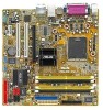
P5LD2-VM specifications summary BIOS features 4 Mb Flash ROM, AMI BIOS, PnP, WfM2.0, DMI2.0, SM BIOS 2.3, ASUS EZ Flash, CrashFree BIOS2, C.P.R. (CPU Parameter Recall) Special features ASUS AI Overclocking ASUS EZ Flash ASUS CrashFree BIOS 2 ASUS MyLogo2™ ASUS CPR (CPU Parameter Recall) I n d u s t r y s t a n d a r d PCI 2.2, USB 2.0 Manageability...pin 12 V plugs) Form Factor Micro-ATX form factor: 9.6 in x 9.6 in Support CD contents Device drivers ASUS PC Probe II ASUS Live Update utility Anti-virus software (OEM version) *Specifications are subject to change without notice. xi...
P5LD2-VM specifications summary BIOS features 4 Mb Flash ROM, AMI BIOS, PnP, WfM2.0, DMI2.0, SM BIOS 2.3, ASUS EZ Flash, CrashFree BIOS2, C.P.R. (CPU Parameter Recall) Special features ASUS AI Overclocking ASUS EZ Flash ASUS CrashFree BIOS 2 ASUS MyLogo2™ ASUS CPR (CPU Parameter Recall) I n d u s t r y s t a n d a r d PCI 2.2, USB 2.0 Manageability...pin 12 V plugs) Form Factor Micro-ATX form factor: 9.6 in x 9.6 in Support CD contents Device drivers ASUS PC Probe II ASUS Live Update utility Anti-virus software (OEM version) *Specifications are subject to change without notice. xi...
P5LD2-VM User's Manual for English Edition
Page 13
This chapter describes the motherboard features and the new technologies it supports. 1Product introduction ASUS P5LD2-VM 1-1
This chapter describes the motherboard features and the new technologies it supports. 1Product introduction ASUS P5LD2-VM 1-1
P5LD2-VM User's Manual for English Edition
Page 14
... hardware devices on it another standout in the 775-land package. See page 1-8 for buying an ASUS® P5LD2-VM motherboard! Before you for details. The motherboard supports the Intel® Pentium® 4 or Intel® Pentium® D processor with a 775...fully compatible with dedicated L2 caches to meet demands for the following items. Motherboard ASUS P5LD2-VM motherboard Cables 2 x Serial ATA signal cables 1 x Ultra DMA 133 cable 1 x Floppy disk drive cable Accessories I/O shield A p p l i c a t i o n C D s ASUS motherboard support CD D o c u m e n t a t i o n User guide ...
... hardware devices on it another standout in the 775-land package. See page 1-8 for buying an ASUS® P5LD2-VM motherboard! Before you for details. The motherboard supports the Intel® Pentium® 4 or Intel® Pentium® D processor with a 775...fully compatible with dedicated L2 caches to meet demands for the following items. Motherboard ASUS P5LD2-VM motherboard Cables 2 x Serial ATA signal cables 1 x Ultra DMA 133 cable 1 x Floppy disk drive cable Accessories I/O shield A p p l i c a t i o n C D s ASUS motherboard support CD D o c u m e n t a t i o n User guide ...
P5LD2-VM User's Manual for English Edition
Page 15
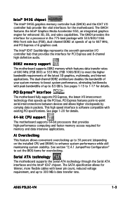
...1066 MHz front side bus (FSB), dual channel DDR2 at speeds of the latest 3D graphics, multimedia, and Internet applications. ASUS P5LD2-VM 1-3 See section "2.4.1 JumperFree Configuration" to -point serial interconnections between devices and allows higher clockspeeds by carrying data in the 775...generation I /O controller hub provide the vital interfaces for the motherboard. See page 1-20 for details. 64-bit CPU support The motherboard supports 64-bit processors that provides high-performance computing and faster memory access required for enhanced 3D, 2D, and video capabilities....
...1066 MHz front side bus (FSB), dual channel DDR2 at speeds of the latest 3D graphics, multimedia, and Internet applications. ASUS P5LD2-VM 1-3 See section "2.4.1 JumperFree Configuration" to -point serial interconnections between devices and allows higher clockspeeds by carrying data in the 775...generation I /O controller hub provide the vital interfaces for the motherboard. See page 1-20 for details. 64-bit CPU support The motherboard supports 64-bit processors that provides high-performance computing and faster memory access required for enhanced 3D, 2D, and video capabilities....

P5LD2-VM User's Manual for English Edition
Page 16
... and damage. With the 8-channel audio ports and S/PDIF interfaces, you to use a DOS-based utility or boot from the support CD in the motherboard allows you can connect your computer into a high-end entertainment system with customizable boot logos. S/PDIF digital ...sound ready The motherboard supports the S/PDIF Out function through the S/PDIF interfaces at midboard. Temperature, fan, and voltage monitoring The CPU temperature is monitored for details. 1.3.2 Innovative ASUS features CrashFree BIOS 2 This feature allows you can easily...
... and damage. With the 8-channel audio ports and S/PDIF interfaces, you to use a DOS-based utility or boot from the support CD in the motherboard allows you can connect your computer into a high-end entertainment system with customizable boot logos. S/PDIF digital ...sound ready The motherboard supports the S/PDIF Out function through the S/PDIF interfaces at midboard. Temperature, fan, and voltage monitoring The CPU temperature is monitored for details. 1.3.2 Innovative ASUS features CrashFree BIOS 2 This feature allows you can easily...

P5LD2-VM User's Manual for English Edition
Page 22
B The CPU fits in only one correct orientation. The motherboard supports Intel® Pentium® D or Intel® Pentium® 4 LGA775 processors with the Intel® Enhanced Memory 64 Technology (EM64T), Enhanced Intel SpeedStep® Technology (...
B The CPU fits in only one correct orientation. The motherboard supports Intel® Pentium® D or Intel® Pentium® 4 LGA775 processors with the Intel® Enhanced Memory 64 Technology (EM64T), Enhanced Intel SpeedStep® Technology (...
P5LD2-VM User's Manual for English Edition
Page 27
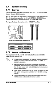
...support memory modules made up of memory module(s) installed per channel must be the same (DIMM_A1 + DIMM_A2 = DIMM_B1 + DIMM_B2). • Always install DIMMs with four Double Data Rate 2 (DDR2) Dual Inline Memory Modules (DIMM) sockets. The figure illustrates the location of the DDR2 DIMM sockets: ® P5LD2-VM DIMM_A1 DIMM_A2 DIMM_B1 DIMM_B2 P5LD2-VM...8226; For dual-channel configuration, the total size of 128 Mb chips or double sided x16 memory modules. ASUS P5LD2-VM 1-15 Refer to the DDR2 Qualified Vendors List on a DDR DIMM socket. DDR2 DIMMs are notched differently ...
...support memory modules made up of memory module(s) installed per channel must be the same (DIMM_A1 + DIMM_A2 = DIMM_B1 + DIMM_B2). • Always install DIMMs with four Double Data Rate 2 (DDR2) Dual Inline Memory Modules (DIMM) sockets. The figure illustrates the location of the DDR2 DIMM sockets: ® P5LD2-VM DIMM_A1 DIMM_A2 DIMM_B1 DIMM_B2 P5LD2-VM...8226; For dual-channel configuration, the total size of 128 Mb chips or double sided x16 memory modules. ASUS P5LD2-VM 1-15 Refer to the DDR2 Qualified Vendors List on a DDR DIMM socket. DDR2 DIMMs are notched differently ...

P5LD2-VM User's Manual for English Edition
Page 28
...S - B - support for this motherboard. Visit the ASUS website (www.asus.com) for the latest DDR2 DIMM modules for 4 modules inserted into the yellow and black slots as one pair of Dual-channel memory configuration. 1-16 Chapter 1: Product introduction Double Sided DIMM Support: A - supports one module inserted into...5C-E SS HYB18T512160AC-3.7 SS E5108AB-5C-E SS HY5PS12821F-C4 SS HYMP564U64AP8-C3 DS HY5PS12821FP-C4 DS E5108AB-5C-E DS E5108AB-5C-E DIMM support AB C ••• ••• ••• •• ••• ••&#...
...S - B - support for this motherboard. Visit the ASUS website (www.asus.com) for the latest DDR2 DIMM modules for 4 modules inserted into the yellow and black slots as one pair of Dual-channel memory configuration. 1-16 Chapter 1: Product introduction Double Sided DIMM Support: A - supports one module inserted into...5C-E SS HYB18T512160AC-3.7 SS E5108AB-5C-E SS HY5PS12821F-C4 SS HYMP564U64AP8-C3 DS HY5PS12821FP-C4 DS E5108AB-5C-E DS E5108AB-5C-E DIMM support AB C ••• ••• ••• •• ••• ••&#...
P5LD2-VM User's Manual for English Edition
Page 29
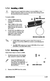
... and the DIMM is properly seated. 2 3 DDR2 DIMM notch Unlocked retaining clip • A DDR2 DIMM is keyed with extra force. 1 2 1 DDR2 DIMM notch 2. ASUS P5LD2-VM 1-17 Firmly insert the DIMM into a socket to avoid damaging the DIMM. • The DDR2 DIMM sockets do so can cause severe damage to unlock... when it flips out with a notch so that the notch on the DIMM matches the break on 1 the socket. 3. Failure to do not support DDR DIMMs. DO not install DDR DIMMs to the DDR2 DIMM sockets. 1.7.5 Removing a DIMM Follow these steps to remove a DIMM. 1. To install a ...
... and the DIMM is properly seated. 2 3 DDR2 DIMM notch Unlocked retaining clip • A DDR2 DIMM is keyed with extra force. 1 2 1 DDR2 DIMM notch 2. ASUS P5LD2-VM 1-17 Firmly insert the DIMM into a socket to avoid damaging the DIMM. • The DDR2 DIMM sockets do so can cause severe damage to unlock... when it flips out with a notch so that the notch on the DIMM matches the break on 1 the socket. 3. Failure to do not support DDR DIMMs. DO not install DDR DIMMs to the DDR2 DIMM sockets. 1.7.5 Removing a DIMM Follow these steps to remove a DIMM. 1. To install a ...
P5LD2-VM User's Manual for English Edition
Page 30
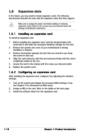
... change the necessary BIOS settings, if any. Turn on the next page. 3. The following sub-sections describe the slots and the expansion cards that they support. Install the software drivers for the card. 2.
... change the necessary BIOS settings, if any. Turn on the next page. 3. The following sub-sections describe the slots and the expansion cards that they support. Install the software drivers for the card. 2.
P5LD2-VM User's Manual for English Edition
Page 31
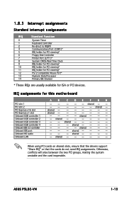
shared - - -- - - - Otherwise, conflicts will arise between the two PCI groups, making the system unstable and the card inoperable. ASUS P5LD2-VM 1-19 shared - shared - - - - - shared - - - - - - shared - - - - - -- - shared - - - - -- - - 1.8.3 Interrupt assignments Standard interrupt ... - - - - IRQ assignments for ISA or PCI devices. shared - - - -- - shared - - - - -- - shared - - -- - - - -- - - shared - - - - - - - - When using PCI cards on shared slots, ensure that the drivers support "Share IRQ" or that the cards do not need IRQ assignments.
shared - - -- - - - Otherwise, conflicts will arise between the two PCI groups, making the system unstable and the card inoperable. ASUS P5LD2-VM 1-19 shared - shared - - - - - shared - - - - - - shared - - - - - -- - shared - - - - -- - - 1.8.3 Interrupt assignments Standard interrupt ... - - - - IRQ assignments for ISA or PCI devices. shared - - - -- - shared - - - - -- - shared - - -- - - - -- - - shared - - - - - - - - When using PCI cards on shared slots, ensure that the drivers support "Share IRQ" or that the cards do not need IRQ assignments.

P5LD2-VM User's Manual for English Edition
Page 32
... PCI Express x1 slot. 1-20 Chapter 1: Product introduction The figure shows a network card installed on the PCI Express x16 slot. 1.8.6 PCI Express x1 This motherboard supports PCI Express x1 network cards, SCSI cards and other cards that comply with PCI specifications. 1.8.4 PCI slots The PCI slots... support cards such as a LAN card, SCSI card, USB card, and other cards that comply with the PCI Express specifications. The figure shows a LAN card installed ...
... PCI Express x1 slot. 1-20 Chapter 1: Product introduction The figure shows a network card installed on the PCI Express x16 slot. 1.8.6 PCI Express x1 This motherboard supports PCI Express x1 network cards, SCSI cards and other cards that comply with PCI specifications. 1.8.4 PCI slots The PCI slots... support cards such as a LAN card, SCSI card, USB card, and other cards that comply with the PCI Express specifications. The figure shows a LAN card installed ...

P5LD2-VM User's Manual for English Edition
Page 37
ITE IDE connector (40-1 pin PRI_EIDE [red]) Supported by the ITE8211F controller, this connector is for Serial ATA hard disk drives. ASUS P5LD2-VM 1-25 GND RSATA_RXN3 RSATA_RXP3 GND RSATA_TXN3 RSATA_TXP3 GND GND RSATA_RXN4 RSATA_RXP4 GND RSATA_TXN4 RSATA_TXP4 GND ® P5LD2-VM SATA3 SATA1 SATA4 SATA2 GND RSATA_TXP1 RSATA_TXN1 GND RSATA_RXP1 RSATA_RXN1 GND GND RSATA_TXP2 RSATA_TXN2 GND...
ITE IDE connector (40-1 pin PRI_EIDE [red]) Supported by the ITE8211F controller, this connector is for Serial ATA hard disk drives. ASUS P5LD2-VM 1-25 GND RSATA_RXN3 RSATA_RXP3 GND RSATA_TXN3 RSATA_TXP3 GND GND RSATA_RXN4 RSATA_RXP4 GND RSATA_TXN4 RSATA_TXP4 GND ® P5LD2-VM SATA3 SATA1 SATA4 SATA2 GND RSATA_TXP1 RSATA_TXN1 GND RSATA_RXP1 RSATA_RXN1 GND GND RSATA_TXP2 RSATA_TXN2 GND...
P5LD2-VM User's Manual for English Edition
Page 38
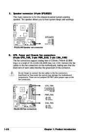
..., 3-pin PWR_RAN, 3-pin CHA_FAN) The fan connectors support cooling fans of 350mA~740mA (8.88W max.) or a total of the connector. The speaker allows you to the fan connectors on the fan connectors. 5. Connect the fan cables to hear system beeps and warnings. ® P5LD2-VM P5LD2-VM Speaker out connector SPEAKER +5V GND GND Speak...
..., 3-pin PWR_RAN, 3-pin CHA_FAN) The fan connectors support cooling fans of 350mA~740mA (8.88W max.) or a total of the connector. The speaker allows you to the fan connectors on the fan connectors. 5. Connect the fan cables to hear system beeps and warnings. ® P5LD2-VM P5LD2-VM Speaker out connector SPEAKER +5V GND GND Speak...
P5LD2-VM User's Manual for English Edition
Page 41
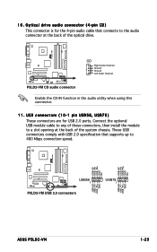
... connectors are for the 4-pin audio cable that supports up to 480 Mbps connection speed. ® P5LD2-VM USB+5V USB_P8USB_P8+ GND NC USB+5V USB_P6USB_P6+ GND NC USB+5V USB_P7USB_P7+ GND USB56 1 P5LD2-VM USB 2.0 connectors USB+5V USB_P5USB_P5+ GND USB78 1 ASUS P5LD2-VM 1-29 ® P5LD2-VM 10. Optical drive audio connector (4-pin CD) ... that connects to a slot opening at the back of the system chassis. CD Right Audio Channel Ground Ground Left Audio Channel P5LD2-VM CD audio connector Enable the CD-IN function in the audio utility when using this connector. 11.
... connectors are for the 4-pin audio cable that supports up to 480 Mbps connection speed. ® P5LD2-VM USB+5V USB_P8USB_P8+ GND NC USB+5V USB_P6USB_P6+ GND NC USB+5V USB_P7USB_P7+ GND USB56 1 P5LD2-VM USB 2.0 connectors USB+5V USB_P5USB_P5+ GND USB78 1 ASUS P5LD2-VM 1-29 ® P5LD2-VM 10. Optical drive audio connector (4-pin CD) ... that connects to a slot opening at the back of the system chassis. CD Right Audio Channel Ground Ground Left Audio Channel P5LD2-VM CD audio connector Enable the CD-IN function in the audio utility when using this connector. 11.
P5LD2-VM User's Manual for English Edition
Page 42
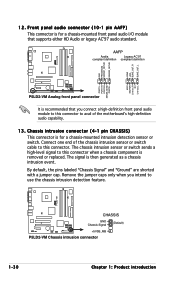
... Chapter 1: Product introduction AAFP Azalia Legacy AC'97 compliant definition compliant definition ® P5LD2-VM AGND +5VA BLINE_OUT_R BLINE_OUT_L GND PRESENCE# SENSE1_RETUR SENSE2_RETUR MIC2 MICPWR Line out_R NC Line out_L PORT1 L PORT1 R PORT2 R SENSE_SEND PORT2 L P5LD2-VM Analog front panel connector It is recommended that supports either HD Audio or legacy AC'97 audio standard.
... Chapter 1: Product introduction AAFP Azalia Legacy AC'97 compliant definition compliant definition ® P5LD2-VM AGND +5VA BLINE_OUT_R BLINE_OUT_L GND PRESENCE# SENSE1_RETUR SENSE2_RETUR MIC2 MICPWR Line out_R NC Line out_L PORT1 L PORT1 R PORT2 R SENSE_SEND PORT2 L P5LD2-VM Analog front panel connector It is recommended that supports either HD Audio or legacy AC'97 audio standard.
P5LD2-VM User's Manual for English Edition
Page 43
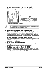
System panel connector (10-1 pin F_PANEL) This connector supports several chassis-mounted functions. ® P5LD2-VM F_PANEL PWRSW PWRLED GND PWR PWR_LEDPWR_LED+ Reset Ground IDE_LEDIDE_LED+ RESET IDE LED * Requires an ATX power supply. Pressing the power button turns the system ON... or written to this connector. Refer to the connector description below for the system power LED. Connect the HDD Activity LED cable to the HDD. ASUS P5LD2-VM 1-31 Pressing the power switch for more than four seconds while the system is ON turns the system OFF. • System Power LED connector (2-pin...
System panel connector (10-1 pin F_PANEL) This connector supports several chassis-mounted functions. ® P5LD2-VM F_PANEL PWRSW PWRLED GND PWR PWR_LEDPWR_LED+ Reset Ground IDE_LEDIDE_LED+ RESET IDE LED * Requires an ATX power supply. Pressing the power button turns the system ON... or written to this connector. Refer to the connector description below for the system power LED. Connect the HDD Activity LED cable to the HDD. ASUS P5LD2-VM 1-31 Pressing the power switch for more than four seconds while the system is ON turns the system OFF. • System Power LED connector (2-pin...
P5LD2-VM User's Manual for English Edition
Page 46
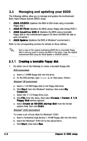
... and updating your BIOS The following to create a bootable floppy disk. A S U S C r a s h F r e e B I O S 2 (Updates the BIOS using the ASUS Update or AFUDOS utilities. 2.1.1 Creating a bootable floppy disk 1. Do either one of boot disks for details on these utilities. DOS environment a. Copy the original motherboard... BIOS using a bootable floppy disk or the motherboard support CD when the BIOS file fails or gets corrupted.) 4. Insert a 1.44 MB floppy disk to the optical drive. ...
... and updating your BIOS The following to create a bootable floppy disk. A S U S C r a s h F r e e B I O S 2 (Updates the BIOS using the ASUS Update or AFUDOS utilities. 2.1.1 Creating a bootable floppy disk 1. Do either one of boot disks for details on these utilities. DOS environment a. Copy the original motherboard... BIOS using a bootable floppy disk or the motherboard support CD when the BIOS file fails or gets corrupted.) 4. Insert a 1.44 MB floppy disk to the optical drive. ...


