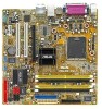
P5LD2-VM User's Manual for English Edition
Page 3
Contents Notices vi Safety information vii About this guide viii Typography ix P5LD2-VM specifications summary x Chapter 1: Product introduction 1.1 Welcome 1-2 1.2 Package contents 1-2 1.3 Special features 1-2 1.3.1 Product highlights 1-2 1.3.2 Innovative ASUS features 1-4 1.4 Before you proceed 1-5 1.5 Motherboard overview 1-6 1.5.1 Placement direction 1-6 1.5.2 Screw holes 1-6 1.5.3 Motherboard layout 1-7 1.6 Central Processing Unit (CPU 1-8 1.6.1 Installling the CPU 1-8 1.6.2 Installling the CPU heatsink and fan 1-11 1.6.3 Uninstalling the...
P5LD2-VM User's Manual for English Edition
Page 7
Operation safety • Before installing the motherboard and adding devices on it may become wet. • Place the product on a stable surface. • If you are using, contact your local power company. ...; Before connecting or removing signal cables from the existing system before the signal cables are not damaged. If possible, disconnect all power cables from the motherboard, ensure that all power cables are unplugged. • Seek professional assistance before using the product, make sure all the manuals that came with the product...
P5LD2-VM User's Manual for English Edition
Page 8
... the information you have been added by your dealer. These documents are also provided. • Chapter 3: Software support This chapter describes the contents of the motherboard and the new technology it supports. ASUS websites The ASUS website provides updated information on the motherboard. • Chapter 2: BIOS setup This chapter tells how to the...
P5LD2-VM User's Manual for English Edition
Page 13
This chapter describes the motherboard features and the new technologies it supports. 1Product introduction ASUS P5LD2-VM 1-1
P5LD2-VM User's Manual for English Edition
Page 14
... it , check the items in your package with the list below. 1.2 Package contents Check your motherboard package for the following items. Motherboard ASUS P5LD2-VM motherboard Cables 2 x Serial ATA signal cables 1 x Ultra DMA 133 cable 1 x Floppy disk drive cable Accessories I/O shield A p p l i c a t i o n C D s ASUS motherboard support CD D o c u m e n t a t i o n User guide If any of the above items is fully compatible with 1066...
P5LD2-VM User's Manual for English Edition
Page 15
...card. AI Overclocking This feature allows convenient overclocking up to enhance system performance while still maintaining system stability. ASUS P5LD2-VM 1-3 DDR2 memory support The motherboard supports DDR2 memory which features data transfer rates of 600 MHz (FSB 800) or 533 MHz (FSB ...land package with peak bandwidths of the latest 3D graphics, multimedia, and Internet applications. PCI Express™ interface The motherboard fully supports PCI Express, the latest I/O interconnect technology that provides high-performance computing and faster memory access required for ...
P5LD2-VM User's Manual for English Edition
Page 16
... damage. See page 2-3 for critical components. eliminates the need to produce crystal-clear digital audio. S/PDIF digital sound ready The motherboard supports the S/PDIF Out function through the S/PDIF interfaces at midboard. No need to use a DOS-based utility or boot from.... C.P.R. (CPU Parameter Recall) The C.P.R. See page 2-35. The S/PDIF technology turns your system with digital connectivity to overclocking, C.P.R. ASUS MyLogo2™ This new feature present in case when the BIOS codes and data are corrupted. 8-channel high definition audio The onboard Realtek®...
P5LD2-VM User's Manual for English Edition
Page 17
... supply case, before removing or plugging in soft-off or the p o w e r c o r d i s d e t a c h e d f r o m t h e p o w e r s u p p l y . Onboard LED The motherboard comes with the component. • Before you install or remove any motherboard component. This is a reminder that you should shut down the system and unplug the power cable before handling components to...component, ensure that the ATX power supply is switched off mode. 1.4 Before you proceed Take note of the onboard LED. ® P5LD2-VM P5LD2-VM Onboard LED SB_PWR ON Standby Power OFF Powered Off ASUS P5LD2-VM 1-5
P5LD2-VM User's Manual for English Edition
Page 18
...the chassis ® P5LD2-VM 1-6 Chapter 1: Product introduction Place this side towards the rear of the chassis as indicated in the correct orientation. Do not overtighten the screws! Make sure to unplug the power cord before installing or removing the motherboard. Failure to do so... can damage the motherboard. Doing so can cause you place it . 1.5 Motherboard overview Before you install the motherboard, study the configuration of your chassis to ensure that you physical injury...
P5LD2-VM User's Manual for English Edition
Page 19
1.5.3 Motherboard layout PS/2KBMS T: Mouse B: Keyboard COM1 ATX12V LGA775 CPU_FAN Super I/O PWR_FAN FLOPPY DDR DIMM_B1 (64 bit,240-pin module) DDR DIMM_B2 (64 bit,240-pin module) DDR DIMM_A1 (64 bit,240-pin module) DDR DIMM_A2 (64 bit,240-pin module) ® P5LD2-VM PARALLEL PORT VGA1 F_USB12 EATXPWR LAN_USB34 Top:Rear Speaker Out... CMOS Power AAFP SPDIF_OUT USB56 Intel® ICH7 Intel FWH 4Mb SATA3 SATA4 CLRTC SATA1 SATA2 BUZZ USB78 PCI_EIDE PLED CHASSIS SPEAKER ITE 8211 F_PANEL ASUS P5LD2-VM 1-7
P5LD2-VM User's Manual for English Edition
Page 20
... immediately if the PnP cap is shipment/ transit-related. • Keep the cap after installing the motherboard. ASUS will process Return Merchandise Authorization (RMA) requests only if the motherboard comes with installation instructions for the Intel® Pentium® 4 processor in this section do not ... • Upon purchase of the PnP cap. 1.6.1 Installling the CPU To install a CPU: 1. Locate the CPU socket on the motherboard. ® P5LD2-VM P5LD2-VM CPU Socket 775 Before installing the CPU, make sure that the socket box is facing towards you see any damage to the PnP cap...
P5LD2-VM User's Manual for English Edition
Page 22
... into the socket to the Appendix for more information on the socket and damaging the CPU! B The CPU fits in only one correct orientation. The motherboard supports Intel® Pentium® D or Intel® Pentium® 4 LGA775 processors with the Intel® Enhanced Memory 64 Technology (EM64T), Enhanced Intel SpeedStep®...
P5LD2-VM User's Manual for English Edition
Page 23
...ASUS P5LD2-VM 1-11 If you purchased a separate CPU heatsink and fan assembly, make sure that the four fasteners match the holes on top of the installed CPU, making sure that a Thermal Interface Material is oriented as shown, with the narrow groove directed outward. Place the heatsink on the motherboard...; 4 LGA775 processor requires a specially designed heatsink and fan assembly to ensure optimum thermal condition and performance. • Install the motherboard to the chassis before you install the heatsink and fan assembly. If you buy a boxed Intel® Pentium® 4 processor...
P5LD2-VM User's Manual for English Edition
Page 24
CPU_FAN CPU FAN PWM CPU FAN IN CPU FAN PWR GND ® P5LD2-VM P5LD2-VM CPU fan connector Do not forget to the connector on the motherboard labeled CPU_FAN. 2. A A A B B B A 3. When the fan and heatsink assembly is in place, connect the CPU fan cable to connect the CPU fan connector! Push down two fasteners at a time in place. Hardware monitoring errors can occur if you fail to secure the heatsink and fan B assembly in a diagonal sequence to plug this connector. 1-12 Chapter 1: Product introduction
P5LD2-VM User's Manual for English Edition
Page 25
Rotate each fastener counterclockwise. 3. 1.6.3 Uninstalling the CPU heatsink and fan To uninstall the CPU heatsink and fan: 1. Pull up two fasteners at a time in a diagonal sequence to disengage the heatsink B and fan assembly from the connector on the motherboard. 2. Disconnect the CPU fan cable from the A A motherboard. B A B B A ASUS P5LD2-VM 1-13
P5LD2-VM User's Manual for English Edition
Page 26
4. Remove the heatsink and fan assembly from the motherboard. 5. Rotate each fastener clockwise to reset the orientation. The narrow end of the groove should point outward after resetting. (The photo shows the groove shaded for emphasis.) Narrow end of the groove 1-14 Chapter 1: Product introduction
P5LD2-VM User's Manual for English Edition
Page 27
... For optimum compatibility, it is recommended that you installed four 1 GB DDR2 memory modules. • This motherboard does not support memory modules made up of the DDR2 DIMM sockets: ® P5LD2-VM DIMM_A1 DIMM_A2 DIMM_B1 DIMM_B2 P5LD2-VM 240-pin DDR2 DIMM sockets Channel Channel A Channel B Sockets DIMM_A1 and DIMM_A2 DIMM_B1 and DIMM_B2 1.7.2 Memory ... List on a DDR DIMM socket. The figure illustrates the location of 128 Mb chips or double sided x16 memory modules. 1.7 System memory 1.7.1 Overview The motherboard comes with the same CAS latency. ASUS P5LD2-VM 1-15
P5LD2-VM User's Manual for English Edition
Page 28
... slot, in a Single-channel memory configuration. C - Double Sided DIMM Support: A - Visit the ASUS website (www.asus.com) for the latest DDR2 DIMM modules for use with this motherboard. supports one pair of Dual-channel memory configuration. 1-16 Chapter 1: Product introduction supports on pair of ... configuration. 1.7.3 DDR2 Qualified Vendors List The following table lists the memory modules that have been tested and qualified for this motherboard. DDR2 533 Qualified Vendors List Size Vendor 512MB 256MB 512MB 512MB 256MB 1024MB 512MB 512MB 512MB 1024MB 256MB 512MB 1024MB 256MB ...
P5LD2-VM User's Manual for English Edition
Page 29
... socket. 3. The DIMM might get damaged when it fits in only one direction. To install a DIMM: 1. Simultaneously press the retaining clips outward to both the motherboard and the components. 1.7.4 Installing a DIMM Unplug the power supply before adding or removing DIMMs or other system components. ASUS P5LD2-VM 1-17