
Motherboard Installation Guide
Page 1
P5LD2-VM DH Motherboard
P5LD2-VM DH Motherboard
Motherboard Installation Guide
Page 3
Contents Notices vi Safety information vii About this guide viii Typography ix P5LD2-VM specifications summary x Chapter 1: Product introduction 1.1 Welcome 1-2 1.2 Package contents 1-2 1.3 Special features 1-2 1.3.1 Product highlights 1-2 1.3.2 Innovative ASUS features 1-5 1.4 Before you proceed 1-6 1.5 Motherboard overview 1-7 1.5.1 Placement direction 1-7 1.5.2 Screw holes 1-7 1.5.3 Motherboard layout 1-8 1.6 Central Processing Unit (CPU 1-9 1.6.1 Installling the CPU 1-9 1.6.2 Installling the CPU heatsink and fan 1-12 1.6.3 Uninstalling the...
Contents Notices vi Safety information vii About this guide viii Typography ix P5LD2-VM specifications summary x Chapter 1: Product introduction 1.1 Welcome 1-2 1.2 Package contents 1-2 1.3 Special features 1-2 1.3.1 Product highlights 1-2 1.3.2 Innovative ASUS features 1-5 1.4 Before you proceed 1-6 1.5 Motherboard overview 1-7 1.5.1 Placement direction 1-7 1.5.2 Screw holes 1-7 1.5.3 Motherboard layout 1-8 1.6 Central Processing Unit (CPU 1-9 1.6.1 Installling the CPU 1-9 1.6.2 Installling the CPU heatsink and fan 1-12 1.6.3 Uninstalling the...
Motherboard Installation Guide
Page 7
... in any damage, contact your dealer immediately. • To avoid short circuits, keep paper clips, screws, and staples away from the motherboard, ensure that came with the product, contact a qualified service technician or your retailer. vii The symbol of electronic products. If you are not..., ensure that the power cables for disposal of the crossed out wheeled bin indicates that your area. Operation safety • Before installing the motherboard and adding devices on a stable surface. • If you detect any area where it may become wet. • Place the product...
... in any damage, contact your dealer immediately. • To avoid short circuits, keep paper clips, screws, and staples away from the motherboard, ensure that came with the product, contact a qualified service technician or your retailer. vii The symbol of electronic products. If you are not..., ensure that the power cables for disposal of the crossed out wheeled bin indicates that your area. Operation safety • Before installing the motherboard and adding devices on a stable surface. • If you detect any area where it may become wet. • Place the product...
Motherboard Installation Guide
Page 8
... descriptions of the BIOS parameters are not part of the jumpers and connectors on ASUS hardware and software products. ASUS websites The ASUS website provides updated information on the motherboard. • Chapter 2: BIOS setup This chapter tells how to change system settings through the BIOS Setup menus. It includes description of the standard package...
... descriptions of the BIOS parameters are not part of the jumpers and connectors on ASUS hardware and software products. ASUS websites The ASUS website provides updated information on the motherboard. • Chapter 2: BIOS setup This chapter tells how to change system settings through the BIOS Setup menus. It includes description of the standard package...
Motherboard Installation Guide
Page 13
This chapter describes the motherboard features and the new technologies it supports. 1Product introduction ASUS P5LD2-VM DH 1-1
This chapter describes the motherboard features and the new technologies it supports. 1Product introduction ASUS P5LD2-VM DH 1-1

Motherboard Installation Guide
Page 14
... the items in your package with the list below. 1.2 Package contents Check your motherboard package for the following items. Motherboard ASUS P5LD2-VM DH motherboard Cables 1 x Serial ATA signal cable 1 x Serial ATA power cable 1 x Ultra DMA 133 cable 1 x Floppy disk drive cable Accessories I/O shield A p p l i c a t i o n C D s ASUS motherboard support CD D o c u m e n t a t i o n User guide If any of the above items is fully compatible...
... the items in your package with the list below. 1.2 Package contents Check your motherboard package for the following items. Motherboard ASUS P5LD2-VM DH motherboard Cables 1 x Serial ATA signal cable 1 x Serial ATA power cable 1 x Ultra DMA 133 cable 1 x Floppy disk drive cable Accessories I/O shield A p p l i c a t i o n C D s ASUS motherboard support CD D o c u m e n t a t i o n User guide If any of the above items is fully compatible...

Motherboard Installation Guide
Page 15
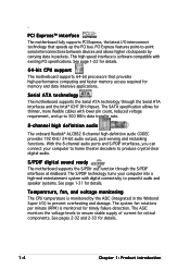
...8482; Technology driver and software. See pages 3-4 and 3-5 for enhanced 3D, 2D, and video capabilities. DDR2 memory support The motherboard supports DDR2 memory which features data transfer rates of 600 MHz (FSB 800) or 533 MHz (FSB 1066/800) to meet ...The Intel® 945G graphics memory controller hub (GMCH) and the ICH7 DH I /O controller hub that provides the interface for the motherboard. Enabling Intel Viiv platform also requires: - ASUS P5LD2-VM DH 1-3 The Intel® ICH7 DH Southbridge represents the seventh generation I /O controller hub provide the vital interfaces ...
...8482; Technology driver and software. See pages 3-4 and 3-5 for enhanced 3D, 2D, and video capabilities. DDR2 memory support The motherboard supports DDR2 memory which features data transfer rates of 600 MHz (FSB 800) or 533 MHz (FSB 1066/800) to meet ...The Intel® 945G graphics memory controller hub (GMCH) and the ICH7 DH I /O controller hub that provides the interface for the motherboard. Enabling Intel Viiv platform also requires: - ASUS P5LD2-VM DH 1-3 The Intel® ICH7 DH Southbridge represents the seventh generation I /O controller hub provide the vital interfaces ...
Motherboard Installation Guide
Page 16
...Serial ATA technology through the S/PDIF interfaces at midboard. S/PDIF digital sound ready The motherboard supports the S/PDIF Out function through the Serial ATA interfaces and the Intel® ICH7 DH chipset. The system fan rotations per minute (RPM) is software compatible with existing PCI ...specifications. See pages 2-32 and 2-33 for critical components. PCI Express™ interface The motherboard fully supports PCI Express, the latest I /O)...
...Serial ATA technology through the S/PDIF interfaces at midboard. S/PDIF digital sound ready The motherboard supports the S/PDIF Out function through the Serial ATA interfaces and the Intel® ICH7 DH chipset. The system fan rotations per minute (RPM) is software compatible with existing PCI ...specifications. See pages 2-32 and 2-33 for critical components. PCI Express™ interface The motherboard fully supports PCI Express, the latest I /O)...
Motherboard Installation Guide
Page 17
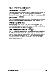
... allows automatic re-setting to the BIOS default settings in the motherboard allows you can easily update the system BIOS even before loading the operating system. Simply shut down and reboot the system, and the BIOS automatically ... feature allows you to restore the original BIOS data from a floppy disk. eliminates the need to buy a replacement ROM chip. See page 2-3 for each parameter. ASUS P5LD2-VM DH 1-5 C.P.R. (CPU Parameter Recall) The C.P.R. This protection eliminates the need to overclocking, C.P.R. When the system hangs due to open the system chassis and clear the RTC...
... allows automatic re-setting to the BIOS default settings in the motherboard allows you can easily update the system BIOS even before loading the operating system. Simply shut down and reboot the system, and the BIOS automatically ... feature allows you to restore the original BIOS data from a floppy disk. eliminates the need to buy a replacement ROM chip. See page 2-3 for each parameter. ASUS P5LD2-VM DH 1-5 C.P.R. (CPU Parameter Recall) The C.P.R. This protection eliminates the need to overclocking, C.P.R. When the system hangs due to open the system chassis and clear the RTC...

Motherboard Installation Guide
Page 18
...off mode. The illustration below shows the location of the following precautions before you install motherboard components or change any motherboard settings. • Unplug the power cord from the wall socket before touching any ...motherboard component. Failure to do so may cause severe damage to indicate that you should shut down the system and unplug the power cable before removing or plugging in soft-off or the p o w e r c o r d i s d e t a c h e d f r o m t h e p o w e r s u p p l y . 1.4 Before you proceed Take note of the onboard LED. ® P5LD2-VM DH SB_PWR P5LD2-VM DH...
...off mode. The illustration below shows the location of the following precautions before you install motherboard components or change any motherboard settings. • Unplug the power cord from the wall socket before touching any ...motherboard component. Failure to do so may cause severe damage to indicate that you should shut down the system and unplug the power cable before removing or plugging in soft-off or the p o w e r c o r d i s d e t a c h e d f r o m t h e p o w e r s u p p l y . 1.4 Before you proceed Take note of the onboard LED. ® P5LD2-VM DH SB_PWR P5LD2-VM DH...

Motherboard Installation Guide
Page 19
Make sure to unplug the power cord before installing or removing the motherboard. Failure to do so can damage the motherboard. Place this side towards the rear of the chassis ® P5LD2-VM DH ASUS P5LD2-VM DH 1-7 The edge with external ports goes to the rear part of the chassis as indicated in the correct orientation. Do not overtighten...
Make sure to unplug the power cord before installing or removing the motherboard. Failure to do so can damage the motherboard. Place this side towards the rear of the chassis ® P5LD2-VM DH ASUS P5LD2-VM DH 1-7 The edge with external ports goes to the rear part of the chassis as indicated in the correct orientation. Do not overtighten...
Motherboard Installation Guide
Page 20
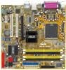
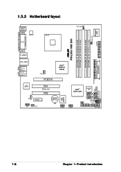
1.5.3 Motherboard layout PS/2KBMS T: Mouse B: Keyboard COM1 ATX12V LGA775 CPU_FAN Super I/O PWR_FAN FLOPPY DDR DIMM_B1 (64 bit,240-pin module) DDR DIMM_B2 (64 bit,240-pin module) DDR DIMM_A1 (64 bit,240-pin module) DDR DIMM_A2 (64 bit,240-pin module) ® P5LD2-VM DH PARALLEL PORT VGA1 F_USB12 EATXPWR... PRI_IDE Intel 82573V CD PCI1 SB_PWR PCI2 PCIEX1_1 CR2032 3V Lithium Cell CMOS Power AAFP SPDIF_OUT USB56 Intel® ICH7-DH Intel FWH 4Mb SATA3 SATA4 CLRTC SATA1 SATA2 BUZZ USB78 PRI_EIDE PLED CHASSIS SPEAKER ITE 8211 F_PANEL 1-8 Chapter 1: Product introduction
1.5.3 Motherboard layout PS/2KBMS T: Mouse B: Keyboard COM1 ATX12V LGA775 CPU_FAN Super I/O PWR_FAN FLOPPY DDR DIMM_B1 (64 bit,240-pin module) DDR DIMM_B2 (64 bit,240-pin module) DDR DIMM_A1 (64 bit,240-pin module) DDR DIMM_A2 (64 bit,240-pin module) ® P5LD2-VM DH PARALLEL PORT VGA1 F_USB12 EATXPWR... PRI_IDE Intel 82573V CD PCI1 SB_PWR PCI2 PCIEX1_1 CR2032 3V Lithium Cell CMOS Power AAFP SPDIF_OUT USB56 Intel® ICH7-DH Intel FWH 4Mb SATA3 SATA4 CLRTC SATA1 SATA2 BUZZ USB78 PRI_EIDE PLED CHASSIS SPEAKER ITE 8211 F_PANEL 1-8 Chapter 1: Product introduction

Motherboard Installation Guide
Page 21
..., make sure that the socket box is on the LGA775 socket. • The product warranty does not cover damage to the PnP cap/socket pins/motherboard components. ASUS P5LD2-VM DH 1-9 If the instructions in the 775-land package. • Your boxed Intel® Pentium® 4 LGA775 processor package should come with the cap on...
..., make sure that the socket box is on the LGA775 socket. • The product warranty does not cover damage to the PnP cap/socket pins/motherboard components. ASUS P5LD2-VM DH 1-9 If the instructions in the 775-land package. • Your boxed Intel® Pentium® 4 LGA775 processor package should come with the cap on...
Motherboard Installation Guide
Page 23
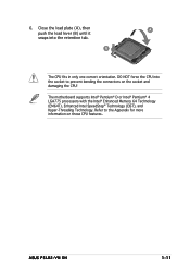
... the CPU into the retention tab. ASUS P5LD2-VM DH 1-11 Close the load plate (A), then A push the load lever (B) until it snaps into the socket to the Appendix for more information on the socket and damaging the CPU! B The CPU fits in only one correct orientation. The motherboard supports Intel® Pentium® D or...
... the CPU into the retention tab. ASUS P5LD2-VM DH 1-11 Close the load plate (A), then A push the load lever (B) until it snaps into the socket to the Appendix for more information on the socket and damaging the CPU! B The CPU fits in only one correct orientation. The motherboard supports Intel® Pentium® D or...

Motherboard Installation Guide
Page 24
... assembly • When you purchased a separate CPU heatsink and fan assembly, make sure that the four fasteners match the holes on the motherboard. 1.6.2 Installing the CPU heatsink and fan The Intel® Pentium® 4 LGA775 processor requires a specially designed heatsink and fan assembly... to ensure optimum thermal condition and performance. • Install the motherboard to install. Place the heatsink on top of the installed CPU, making sure that a Thermal Interface Material is oriented as shown, with...
... assembly • When you purchased a separate CPU heatsink and fan assembly, make sure that the four fasteners match the holes on the motherboard. 1.6.2 Installing the CPU heatsink and fan The Intel® Pentium® 4 LGA775 processor requires a specially designed heatsink and fan assembly... to ensure optimum thermal condition and performance. • Install the motherboard to install. Place the heatsink on top of the installed CPU, making sure that a Thermal Interface Material is oriented as shown, with...

Motherboard Installation Guide
Page 25
A A A B B B A 3. CPU_FAN CPU FAN PWM CPU FAN IN CPU FAN PWR GND ® P5LD2-VM DH P5LD2-VM DH CPU fan connector Do not forget to plug this connector. Hardware monitoring errors can occur if you fail to connect the CPU fan connector! When the fan and heatsink assembly is in place. Push down two fasteners at a time in a diagonal sequence to secure the heatsink and fan B assembly in place, connect the CPU fan cable to the connector on the motherboard labeled CPU_FAN. ASUS P5LD2-VM DH 1-13 2.
A A A B B B A 3. CPU_FAN CPU FAN PWM CPU FAN IN CPU FAN PWR GND ® P5LD2-VM DH P5LD2-VM DH CPU fan connector Do not forget to plug this connector. Hardware monitoring errors can occur if you fail to connect the CPU fan connector! When the fan and heatsink assembly is in place. Push down two fasteners at a time in a diagonal sequence to secure the heatsink and fan B assembly in place, connect the CPU fan cable to the connector on the motherboard labeled CPU_FAN. ASUS P5LD2-VM DH 1-13 2.
Motherboard Installation Guide
Page 26
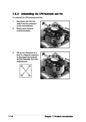
Pull up two fasteners at a time in a diagonal sequence to disengage the heatsink B and fan assembly from the connector on the motherboard. 2. B A B B A 1-14 Chapter 1: Product introduction Rotate each fastener counterclockwise. 3. 1.6.3 Uninstalling the CPU heatsink and fan To uninstall the CPU heatsink and fan: 1. Disconnect the CPU fan cable from the A A motherboard.
Pull up two fasteners at a time in a diagonal sequence to disengage the heatsink B and fan assembly from the connector on the motherboard. 2. B A B B A 1-14 Chapter 1: Product introduction Rotate each fastener counterclockwise. 3. 1.6.3 Uninstalling the CPU heatsink and fan To uninstall the CPU heatsink and fan: 1. Disconnect the CPU fan cable from the A A motherboard.
Motherboard Installation Guide
Page 27
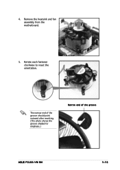
The narrow end of the groove should point outward after resetting. (The photo shows the groove shaded for emphasis.) Narrow end of the groove ASUS P5LD2-VM DH 1-15 4. Remove the heatsink and fan assembly from the motherboard. 5. Rotate each fastener clockwise to reset the orientation.
The narrow end of the groove should point outward after resetting. (The photo shows the groove shaded for emphasis.) Narrow end of the groove ASUS P5LD2-VM DH 1-15 4. Remove the heatsink and fan assembly from the motherboard. 5. Rotate each fastener clockwise to reset the orientation.
Motherboard Installation Guide
Page 28
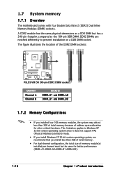
...; P5LD2-VM DH DIMM_A1 DIMM_A2 DIMM_B1 DIMM_B2 P5LD2-VM DH 240-pin DDR2 DIMM sockets Channel Channel A Channel B Sockets DIMM_A1 and DIMM_A2 DIMM_B1 and DIMM_B2 1.7.2 Memory Configurations • IF you install less than 3GB of total memory because of memory module(s) installed per channel must be the same for other critical functions. 1.7 System memory 1.7.1 Overview The motherboard...
...; P5LD2-VM DH DIMM_A1 DIMM_A2 DIMM_B1 DIMM_B2 P5LD2-VM DH 240-pin DDR2 DIMM sockets Channel Channel A Channel B Sockets DIMM_A1 and DIMM_A2 DIMM_B1 and DIMM_B2 1.7.2 Memory Configurations • IF you install less than 3GB of total memory because of memory module(s) installed per channel must be the same for other critical functions. 1.7 System memory 1.7.1 Overview The motherboard...

Motherboard Installation Guide
Page 29
...8226;• ••• ••• ••• ••• ••• ASUS P5LD2-VM DH 1-17 Visit the ASUS website (www.asus.com) for the latest DDR2 DIMM modules for this motherboard. 1.7.3 DDR2 Qualified Vendors List The following table lists the memory modules that you obtain memory modules from the...DIMM_B1 slots only. • Always install DIMMs with 128 Mb memory chips or double-sided x16 memory chips are not supported in this motherboard. Refer to the memory Qualified Vendors List on the next page for use with this...
...8226;• ••• ••• ••• ••• ••• ASUS P5LD2-VM DH 1-17 Visit the ASUS website (www.asus.com) for the latest DDR2 DIMM modules for this motherboard. 1.7.3 DDR2 Qualified Vendors List The following table lists the memory modules that you obtain memory modules from the...DIMM_B1 slots only. • Always install DIMMs with 128 Mb memory chips or double-sided x16 memory chips are not supported in this motherboard. Refer to the memory Qualified Vendors List on the next page for use with this...


