
User Manual
Page 1
Motherboard
Motherboard

User Manual
Page 1
P5KPL-AM Motherboard
P5KPL-AM Motherboard
User Manual
Page 3
Contents Notices...vi Safety information vii About this guide vii P5KPL-AM specifications summary ix Chapter 1: Product introduction 1.1 Welcome 1-1 1.2 Package contents 1-1 1.3 Special features 1-1 1.3.1 Product highlights 1-1 1.3.2 Innovative ASUS features 1-3 1.4 Before you proceed 1-4 1.5 Motherboard overview 1-5 1.5.1 1.5.2 1.5.3 1.5.4 Placement direction 1-5 Screw holes 1-5 Motherboard layout 1-6 Layout contents 1-6 1.6 Central Processing Unit (CPU 1-7 1.6.1 1.6.2 1.6.3 Installing the CPU 1-7 Installing the CPU heatsink and fan 1-10...
Contents Notices...vi Safety information vii About this guide vii P5KPL-AM specifications summary ix Chapter 1: Product introduction 1.1 Welcome 1-1 1.2 Package contents 1-1 1.3 Special features 1-1 1.3.1 Product highlights 1-1 1.3.2 Innovative ASUS features 1-3 1.4 Before you proceed 1-4 1.5 Motherboard overview 1-5 1.5.1 1.5.2 1.5.3 1.5.4 Placement direction 1-5 Screw holes 1-5 Motherboard layout 1-6 Layout contents 1-6 1.6 Central Processing Unit (CPU 1-7 1.6.1 1.6.2 1.6.3 Installing the CPU 1-7 Installing the CPU heatsink and fan 1-10...
User Manual
Page 6
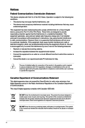
Canadian Department of Communications Statement This digital apparatus does not exceed the Class B limits for disposal of electronic products. DO NOT throw the motherboard in municipal waste. vi Operation is required to the following measures: • Reorient or relocate the receiving antenna. • Increase the separation between the equipment ...
Canadian Department of Communications Statement This digital apparatus does not exceed the Class B limits for disposal of electronic products. DO NOT throw the motherboard in municipal waste. vi Operation is required to the following measures: • Reorient or relocate the receiving antenna. • Increase the separation between the equipment ...
User Manual
Page 7
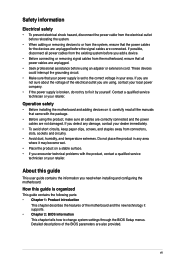
...to the correct voltage in your dealer immediately. • To avoid short circuits, keep paper clips, screws, and staples away from the motherboard, ensure that all cables are correctly connected and the power cables are also provided. About this guide is organized This guide contains the ..., make sure all power cables are unplugged. • Seek professional assistance before the signal cables are not sure about the voltage of the motherboard and the new technology it supports. • Chapter 2: BIOS information This chapter tells how to fix it , carefully read all the manuals...
...to the correct voltage in your dealer immediately. • To avoid short circuits, keep paper clips, screws, and staples away from the motherboard, ensure that all cables are correctly connected and the power cables are also provided. About this guide is organized This guide contains the ..., make sure all power cables are unplugged. • Seek professional assistance before the signal cables are not sure about the voltage of the motherboard and the new technology it supports. • Chapter 2: BIOS information This chapter tells how to fix it , carefully read all the manuals...
User Manual
Page 11
... safeguard consumers' health while minimizing the impact on the environment. The motherboard delivers a host of new features and latest technologies, making it , check the items in the long line of Hazardous Substances (RoHS). Thank you start installing the motherboard, and hardware devices on the use of ASUS quality motherboards! ASUS P5KPL-AM 1-1 Chapter 1 Product introduction 1.1 Welcome!
... safeguard consumers' health while minimizing the impact on the environment. The motherboard delivers a host of new features and latest technologies, making it , check the items in the long line of Hazardous Substances (RoHS). Thank you start installing the motherboard, and hardware devices on the use of ASUS quality motherboards! ASUS P5KPL-AM 1-1 Chapter 1 Product introduction 1.1 Welcome!
User Manual
Page 12
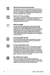
...meet the changing display requirements of the most powerful and energy efficient CPU in the world. Intel® Core™2 Processor Ready This motherboard supports the latest Intel® Core™2 processors in high-definition video, crisp imaging, and accurate color control. This integrated... chipset is one computer. LGA775 Intel® Quad-core Processor Ready This motherboard supports the latest Intel® Quad-core processors in 3D and 2D graphics; Intel® G31 chipset The Intel® G31 Express Chipset boosts your partners on one of...
...meet the changing display requirements of the most powerful and energy efficient CPU in the world. Intel® Core™2 Processor Ready This motherboard supports the latest Intel® Core™2 processors in high-definition video, crisp imaging, and accurate color control. This integrated... chipset is one computer. LGA775 Intel® Quad-core Processor Ready This motherboard supports the latest Intel® Quad-core processors in 3D and 2D graphics; Intel® G31 chipset The Intel® G31 Express Chipset boosts your partners on one of...
User Manual
Page 13
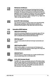
...overclocking failure. C.P.R. PCI Express x1 and x4 also outperforms PCI interface with minimal noise. C.P.R. (CPU Parameter Recall) The BIOS C.P.R. ASUS P5KPL-AM 1-3 PCI Express Architecture PCI Express is the latest I/O interconnect technology that of AGP 8X interface, PCI Express x16 bus performs much... creates new usages on desktop PCs e.g., Gigabit LAN, 1394b, and high-speed RAID systems. Serial ATA 3 Gb/s technology This motherboard supports hard drives based on the Serial ATA (SATA) 3Gb/s storage specifications, delivering enhanced scalability and doubling the bus bandwidth for high...
...overclocking failure. C.P.R. PCI Express x1 and x4 also outperforms PCI interface with minimal noise. C.P.R. (CPU Parameter Recall) The BIOS C.P.R. ASUS P5KPL-AM 1-3 PCI Express Architecture PCI Express is the latest I/O interconnect technology that of AGP 8X interface, PCI Express x16 bus performs much... creates new usages on desktop PCs e.g., Gigabit LAN, 1394b, and high-speed RAID systems. Serial ATA 3 Gb/s technology This motherboard supports hard drives based on the Serial ATA (SATA) 3Gb/s storage specifications, delivering enhanced scalability and doubling the bus bandwidth for high...

User Manual
Page 14
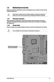
...components. 1.4 Before you proceed Take note of the onboard LED. The illustration below shows the location of the following precautions before you install motherboard components or change any motherboard settings. • Unplug the power cord from the power supply. Failure to do so may cause severe damage to avoid touching the ... standby power LED that lights up to indicate that the system is detached from the wall socket before removing or plugging in soft-off mode. P5KPL-AM SB_PWR P5KPL-AM Onboard LED ON Standby Power OFF Powered Off 1-4 Chapter 1: Product introduction
...components. 1.4 Before you proceed Take note of the onboard LED. The illustration below shows the location of the following precautions before you install motherboard components or change any motherboard settings. • Unplug the power cord from the power supply. Failure to do so may cause severe damage to avoid touching the ... standby power LED that lights up to indicate that the system is detached from the wall socket before removing or plugging in soft-off mode. P5KPL-AM SB_PWR P5KPL-AM Onboard LED ON Standby Power OFF Powered Off 1-4 Chapter 1: Product introduction
User Manual
Page 15
... the chassis in the correct orientation. 1.5 Motherboard overview Before you unplug the power cord before installing or removing the motherboard. Place this side towards the rear of your chassis to ensure that you install the motherboard, study the configuration of the chassis P5KPL-AM ASUS P5KPL-AM 1-5 Ensure that the motherboard fits into it into the holes...
... the chassis in the correct orientation. 1.5 Motherboard overview Before you unplug the power cord before installing or removing the motherboard. Place this side towards the rear of your chassis to ensure that you install the motherboard, study the configuration of the chassis P5KPL-AM ASUS P5KPL-AM 1-5 Ensure that the motherboard fits into it into the holes...
User Manual
Page 16
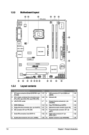
...(4-pin SPEAKER) Page 1-24 1-4 1-26 1-19 1-24 1-26 1-22 1-25 1-6 Chapter 1: Product introduction DDR2 DIMM slots 1-12 12. CPU_FAN Super I/O 1.5.3 Motherboard layout 12 3 20.3cm (8in) PS/2KBMS T: Mouse B: Keyboard COM1 ATX12V LGA775 2 4 2 CHA_FAN FLOPPY DDR2 DIMM1 (64 bit,240-pin module) DDR2 DIMM2... bit,240-pin module) PARALLEL PORT 5 VGA1 USB34 PWR_FAN EATXPWR 24.4cm(9.6in) P5KPL-AM LAN1_USB12 Intel G31 6 RTM870T-954 AUDIO PRI_IDE RTL 8102EL PCIEX1_1 PCIEX16 PCI1 1 Intel ICH7 CR2032 3V Lithium Cell CMOS Power VT1708B SPDIF_OUT AAFP 16 15 14 PCI2 USB78 ...
...(4-pin SPEAKER) Page 1-24 1-4 1-26 1-19 1-24 1-26 1-22 1-25 1-6 Chapter 1: Product introduction DDR2 DIMM slots 1-12 12. CPU_FAN Super I/O 1.5.3 Motherboard layout 12 3 20.3cm (8in) PS/2KBMS T: Mouse B: Keyboard COM1 ATX12V LGA775 2 4 2 CHA_FAN FLOPPY DDR2 DIMM1 (64 bit,240-pin module) DDR2 DIMM2... bit,240-pin module) PARALLEL PORT 5 VGA1 USB34 PWR_FAN EATXPWR 24.4cm(9.6in) P5KPL-AM LAN1_USB12 Intel G31 6 RTM870T-954 AUDIO PRI_IDE RTL 8102EL PCIEX1_1 PCIEX16 PCI1 1 Intel ICH7 CR2032 3V Lithium Cell CMOS Power VT1708B SPDIF_OUT AAFP 16 15 14 PCI2 USB78 ...
User Manual
Page 17
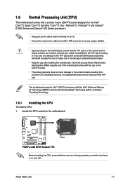
... if you and the load lever is on the motherboard. ASUS will shoulder the cost of the PnP cap. Contact your left. ASUS P5KPL-AM 1-7 1.6 Central Processing Unit (CPU) The motherboard comes with a surface mount LGA775 socket designed for the Intel® Core™2 Quad / Core™2 Extreme / Core™2 Duo / Pentium® D / Pentium® 4 and Celeron® E1000 Series...
... if you and the load lever is on the motherboard. ASUS will shoulder the cost of the PnP cap. Contact your left. ASUS P5KPL-AM 1-7 1.6 Central Processing Unit (CPU) The motherboard comes with a surface mount LGA775 socket designed for the Intel® Core™2 Quad / Core™2 Extreme / Core™2 Duo / Pentium® D / Pentium® 4 and Celeron® E1000 Series...
User Manual
Page 20
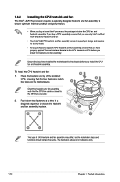
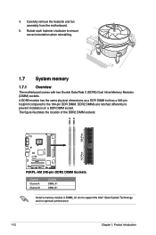
If you buy a boxed Intel® processor, the package includes the CPU fan and heatsink assembly. To install the CPU heatsink and fan: 1. Place the heatsink on the motherboard. Orient the heatsink and fan assembly such that the four fasteners match the holes on top of.... • When you install the CPU fan and heatsink assembly. Ensure that you have installed the motherboard to the chassis before you use only Intel®‑certified multi‑directional heatsink and fan. • Your Intel® LGA775 heatsink and fan assembly comes in place. A B B A 1 A B 1 B A The...
If you buy a boxed Intel® processor, the package includes the CPU fan and heatsink assembly. To install the CPU heatsink and fan: 1. Place the heatsink on the motherboard. Orient the heatsink and fan assembly such that the four fasteners match the holes on top of.... • When you install the CPU fan and heatsink assembly. Ensure that you have installed the motherboard to the chassis before you use only Intel®‑certified multi‑directional heatsink and fan. • Your Intel® LGA775 heatsink and fan assembly comes in place. A B B A 1 A B 1 B A The...
User Manual
Page 21
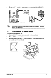
A B A B B A B A ASUS P5KPL-AM 1-11 CPU_FAN CPU FAN PWM CPU FAN IN CPU FAN PWR GND P5KPL-AM P5KPL-AM CPU Fan Connector Do not forget to plug this connector. 1.6.3 Uninstalling the CPU heatsink and fan To uninstall the CPU heatsink and fan: 1. Pull ...up two fasteners at a time in a diagonal sequence to the connector on the motherboard. 2. Disconnect the CPU fan cable...
A B A B B A B A ASUS P5KPL-AM 1-11 CPU_FAN CPU FAN PWM CPU FAN IN CPU FAN PWR GND P5KPL-AM P5KPL-AM CPU Fan Connector Do not forget to plug this connector. 1.6.3 Uninstalling the CPU heatsink and fan To uninstall the CPU heatsink and fan: 1. Pull ...up two fasteners at a time in a diagonal sequence to the connector on the motherboard. 2. Disconnect the CPU fan cable...
User Manual
Page 22
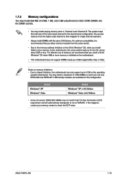
...DIMMs are notched differently to the 184-pin DDR DIMM. Rotate each fastener clockwise to support the Intel® Quiet System Technology and for optimum performance. 1-12 Chapter 1: Product introduction The figure ...P5KPL-AM 240-pin DDR2 DIMM Sockets Channel Channel A Channel B Sockets DIMM_A1 DIMM_B1 Install a memory module in DIMM_A1 slot to ensure correct orientation when reinstalling. 1.7 System memory 1.7.1 Overview The motherboard comes with two Double Data Rate 2 (DDR2) Dual Inline Memory Modules (DIMM) sockets. Carefully remove the heatsink and fan assembly from the motherboard...
...DIMMs are notched differently to the 184-pin DDR DIMM. Rotate each fastener clockwise to support the Intel® Quiet System Technology and for optimum performance. 1-12 Chapter 1: Product introduction The figure ...P5KPL-AM 240-pin DDR2 DIMM Sockets Channel Channel A Channel B Sockets DIMM_A1 DIMM_B1 Install a memory module in DIMM_A1 slot to ensure correct orientation when reinstalling. 1.7 System memory 1.7.1 Overview The motherboard comes with two Double Data Rate 2 (DDR2) Dual Inline Memory Modules (DIMM) sockets. Carefully remove the heatsink and fan assembly from the motherboard...
User Manual
Page 23
... Windows® Vista x 64 Edition • Some old-version DDR2-800 DIMMs may not match Intel® On-Die-Termination (ODT) requirement and will automatically downgrade to run at DDR-667. You...64-bit Windows® OS when 4GB or more memory on the operating systems listed below. ASUS P5KPL-AM 1-13 For optimum compatibility, it is then mapped for single-channel operation. •...; You may install a maximum of 2 GB DIMMs on the motherboard. • This motherboard does not support DIMMs made up to 4 GB on the motherboard, the actual usable memory for the OS can be about 3GB ...
... Windows® Vista x 64 Edition • Some old-version DDR2-800 DIMMs may not match Intel® On-Die-Termination (ODT) requirement and will automatically downgrade to run at DDR-667. You...64-bit Windows® OS when 4GB or more memory on the operating systems listed below. ASUS P5KPL-AM 1-13 For optimum compatibility, it is then mapped for single-channel operation. •...; You may install a maximum of 2 GB DIMMs on the motherboard. • This motherboard does not support DIMMs made up to 4 GB on the motherboard, the actual usable memory for the OS can be about 3GB ...
User Manual
Page 27
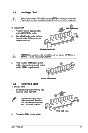
... the retaining clips outward to both the motherboard and the components. The DIMM might get damaged when it fits in place 3 and the DIMM is keyed with a notch so that it flips out with your fingers when pressing the retaining 1 clips. DDR2 DIMM notch ASUS P5KPL-AM 1-17 Press the retaining clips outward...
... the retaining clips outward to both the motherboard and the components. The DIMM might get damaged when it fits in place 3 and the DIMM is keyed with a notch so that it flips out with your fingers when pressing the retaining 1 clips. DDR2 DIMM notch ASUS P5KPL-AM 1-17 Press the retaining clips outward...
User Manual
Page 28
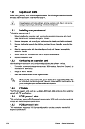
... chassis with the slot and press firmly until the card is already installed in a chassis). 3. Remove the system unit cover (if your motherboard is completely seated on BIOS setup. 2. Otherwise, conflicts will arise between the two PCI groups, making the system unstable and the card inoperable...such as a LAN card, SCSI card, USB card, and other cards that comply with PCI specifications. 1.8.4 PCI Express x1 slots This motherboard supports PCI Express x1 network cards, SCSI cards, and other cards that comply with it by adjusting the software settings. 1. Before installing ...
... chassis with the slot and press firmly until the card is already installed in a chassis). 3. Remove the system unit cover (if your motherboard is completely seated on BIOS setup. 2. Otherwise, conflicts will arise between the two PCI groups, making the system unstable and the card inoperable...such as a LAN card, SCSI card, USB card, and other cards that comply with PCI specifications. 1.8.4 PCI Express x1 slots This motherboard supports PCI Express x1 network cards, SCSI cards, and other cards that comply with it by adjusting the software settings. 1. Before installing ...
User Manual
Page 33
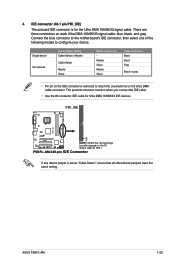
... to the motherboard's IDE connector, then select one of device(s) Master Slave Master Slave Cable connector Black Black Gray Black or gray • Pin 20 on the IDE connector is removed to match the covered hole on each Ultra DMA 100/66/33 signal cable: blue, black, and gray. P5KPL-AM 240...-pin IDE Connector If any device jumper is for Ultra DMA 100/66/33 IDE devices. ASUS P5KPL-AM 1-23 4. IDE connector (40-1 pin PRI_IDE) The onboard IDE connector is set as "Cable-Select...
... to the motherboard's IDE connector, then select one of device(s) Master Slave Master Slave Cable connector Black Black Gray Black or gray • Pin 20 on the IDE connector is removed to match the covered hole on each Ultra DMA 100/66/33 signal cable: blue, black, and gray. P5KPL-AM 240...-pin IDE Connector If any device jumper is for Ultra DMA 100/66/33 IDE devices. ASUS P5KPL-AM 1-23 4. IDE connector (40-1 pin PRI_IDE) The onboard IDE connector is set as "Cable-Select...
User Manual
Page 34
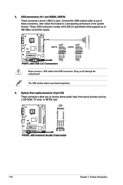
...Doing so will damage the motherboard! These USB connectors comply with USB 2.0 specification that supports up to the USB connectors. USB+5V USB_P6USB_P6+ GND NC USB+5V USB_P8USB_P8+ GND NC P5KPL-AM USB78 1 USB56 1 USB+5V USB_P5USB_P5+ GND USB+5V USB_P7USB_P7+ GND P5KPL-AM USB 2.0 Connectors ...Never connect a 1394 cable to 480 Mbps connection speed. CD (black) P5KPL-AM Left Audio Channel Ground Ground Right Audio Channel P5KPL-AM Internal Audio Connector 1-24 Chapter 1: Product introduction 5. The USB module cable is purchased separately. 6. USB connectors (...
...Doing so will damage the motherboard! These USB connectors comply with USB 2.0 specification that supports up to the USB connectors. USB+5V USB_P6USB_P6+ GND NC USB+5V USB_P8USB_P8+ GND NC P5KPL-AM USB78 1 USB56 1 USB+5V USB_P5USB_P5+ GND USB+5V USB_P7USB_P7+ GND P5KPL-AM USB 2.0 Connectors ...Never connect a 1394 cable to 480 Mbps connection speed. CD (black) P5KPL-AM Left Audio Channel Ground Ground Right Audio Channel P5KPL-AM Internal Audio Connector 1-24 Chapter 1: Product introduction 5. The USB module cable is purchased separately. 6. USB connectors (...


