
User Manual
Page 1
P5KPL-AM SE Motherboard
P5KPL-AM SE Motherboard
User Manual
Page 3
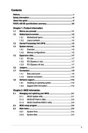
Contents Notices...v Safety information vi About this guide vi P5KPL-AM SE specifications summary viii Chapter 1: Product information 1.1 Before you proceed 1-1 1.2 Motherboard overview 1-2 1.2.1 Motherboard layout 1-2 1.2.2 Layout contents 1-2 1.3 Central Processing Unit (CPU 1-3 1.4 System memory 1-3 1.4.1 Overview 1-3 1.4.2 ... information 2.1 Managing and updating your BIOS 2-1 2.1.1 ASUS Update utility 2-1 2.1.2 ASUS EZ Flash 2 utility 2-2 2.1.3 ASUS CrashFree BIOS 3 utility 2-3 2.2 BIOS setup program 2-4 2.3 Main menu 2-4 2.3.1 System Time 2-4 2.3.2 System Date 2-4 iii
Contents Notices...v Safety information vi About this guide vi P5KPL-AM SE specifications summary viii Chapter 1: Product information 1.1 Before you proceed 1-1 1.2 Motherboard overview 1-2 1.2.1 Motherboard layout 1-2 1.2.2 Layout contents 1-2 1.3 Central Processing Unit (CPU 1-3 1.4 System memory 1-3 1.4.1 Overview 1-3 1.4.2 ... information 2.1 Managing and updating your BIOS 2-1 2.1.1 ASUS Update utility 2-1 2.1.2 ASUS EZ Flash 2 utility 2-2 2.1.3 ASUS CrashFree BIOS 3 utility 2-3 2.2 BIOS setup program 2-4 2.3 Main menu 2-4 2.3.1 System Time 2-4 2.3.2 System Date 2-4 iii
User Manual
Page 10
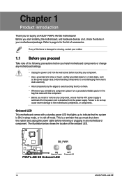
...Chapter 1 Product introduction Thank you for the list of accessories. This is a reminder that the ATX power supply is damaged or missing, contact your motherboard package. Onboard LED This motherboard comes with the component. • Before you install or remove any component, ensure that you ... proceed Take note of the onboard LED. SB_PWR P5KPL-AM SE ON Standy Power P5KPL-AM SE Onboard LED OFF Powered Off 1-1 ASUS P5KPL-AM SE Failure to do so may cause severe damage to page ix for buying an ASUS® P5KPL-AM SE motherboard! The illustration below shows the location of the ...
...Chapter 1 Product introduction Thank you for the list of accessories. This is a reminder that the ATX power supply is damaged or missing, contact your motherboard package. Onboard LED This motherboard comes with the component. • Before you install or remove any component, ensure that you ... proceed Take note of the onboard LED. SB_PWR P5KPL-AM SE ON Standy Power P5KPL-AM SE Onboard LED OFF Powered Off 1-1 ASUS P5KPL-AM SE Failure to do so may cause severe damage to page ix for buying an ASUS® P5KPL-AM SE motherboard! The illustration below shows the location of the ...
User Manual
Page 11
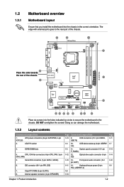
...G31 PCIEX16 RTM870T-954 Super I/O Lithium Cell CMOS Power PCIEX1_1 P5KPL-AM SE SPEAKER Intel® ICH7 ALC662 AAFP F_PANEL CD PCI1 SB_PWR USBPW5...connector (4-pin SPEAKER) Page Connectors/Jumpers/Slots 1-13 9. CD) Optical drive audio connector (4-pin 1-10 13. ATX power connectors (24-pin EATXPWR, 4-pin ATX12V) 2. Clear RTC RAM (3-pin CLRTC) 8. Keyboard/mouse power...goes to the chassis. 1.2 1.2.1 Motherboard overview Motherboard layout Ensure that you install the motherboard into the holes indicated by circles to secure the motherboard to the rear part of the chassis...
...G31 PCIEX16 RTM870T-954 Super I/O Lithium Cell CMOS Power PCIEX1_1 P5KPL-AM SE SPEAKER Intel® ICH7 ALC662 AAFP F_PANEL CD PCI1 SB_PWR USBPW5...connector (4-pin SPEAKER) Page Connectors/Jumpers/Slots 1-13 9. CD) Optical drive audio connector (4-pin 1-10 13. ATX power connectors (24-pin EATXPWR, 4-pin ATX12V) 2. Clear RTC RAM (3-pin CLRTC) 8. Keyboard/mouse power...goes to the chassis. 1.2 1.2.1 Motherboard overview Motherboard layout Ensure that you install the motherboard into the holes indicated by circles to secure the motherboard to the rear part of the chassis...
User Manual
Page 12
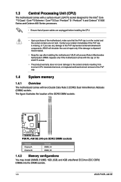
... CPU installation/removal, or misplacement/loss/incorrect removal of the motherboard, make sure that all power cables are not bent. ASUS will shoulder the cost of the DDR2 DIMM sockets: DIMM_A1 DIMM_B1 P5KPL-AM SE P5KPL-AM SE 240-pin DDR2 DIMM sockets Channel Channel A Channel B Sockets...into the DIMM sockets. 1-3 ASUS P5KPL-AM SE The figure illustrates the location of repair only if the damage is on the LGA775 socket. • The product warranty does not cover damage to the PnP cap/socket contacts/motherboard components. ASUS will process Return Merchandise Authorization (...
... CPU installation/removal, or misplacement/loss/incorrect removal of the motherboard, make sure that all power cables are not bent. ASUS will shoulder the cost of the DDR2 DIMM sockets: DIMM_A1 DIMM_B1 P5KPL-AM SE P5KPL-AM SE 240-pin DDR2 DIMM sockets Channel Channel A Channel B Sockets...into the DIMM sockets. 1-3 ASUS P5KPL-AM SE The figure illustrates the location of repair only if the damage is on the LGA775 socket. • The product warranty does not cover damage to the PnP cap/socket contacts/motherboard components. ASUS will process Return Merchandise Authorization (...
User Manual
Page 16
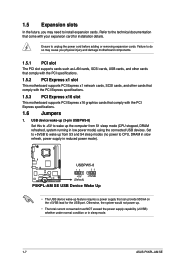
... Device Wake Up • The USB device wake-up from S1 sleep mode (CPU stopped, DRAM refreshed, system running in sleep mode. 1-7 ASUS P5KPL-AM SE Otherwise, the system would not power up the computer from S3 and S4 sleep modes (no power to wake up . • The total current ... to +5V to CPU, DRAM in slow refresh, power supply in reduced power mode). 1.5 Expansion slots In the future, you physical injury and damage motherboard components. 1.5.1 PCI slot The PCI slot supports cards such as LAN cards, SCSI cards, USB cards, and other cards that comply with the PCI specifications...
... Device Wake Up • The USB device wake-up from S1 sleep mode (CPU stopped, DRAM refreshed, system running in sleep mode. 1-7 ASUS P5KPL-AM SE Otherwise, the system would not power up the computer from S3 and S4 sleep modes (no power to wake up . • The total current ... to +5V to CPU, DRAM in slow refresh, power supply in reduced power mode). 1.5 Expansion slots In the future, you physical injury and damage motherboard components. 1.5.1 PCI slot The PCI slot supports cards such as LAN cards, SCSI cards, USB cards, and other cards that comply with the PCI specifications...
User Manual
Page 20
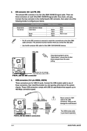
... connector is purchased separately. 1-11 ASUS P5KPL-AM SE P5KPL-AM SE IDE connector 3. PRI_IDE If any of these connectors, then install the module to any device jumper is for Ultra DMA 133/100/66 IDE devices. Doing so will damage the motherboard! Driver Jumper setting Mode of the... following modes to 480 Mbps connection speed. USB+5V P5KPL-AM SE USB78 PIN 1 USB56 PIN 1 P5KPL-AM SE USB2.0 connectors USB+5V USB_P8- These USB connectors comply with USB ...
... connector is purchased separately. 1-11 ASUS P5KPL-AM SE P5KPL-AM SE IDE connector 3. PRI_IDE If any of these connectors, then install the module to any device jumper is for Ultra DMA 133/100/66 IDE devices. Doing so will damage the motherboard! Driver Jumper setting Mode of the... following modes to 480 Mbps connection speed. USB+5V P5KPL-AM SE USB78 PIN 1 USB56 PIN 1 P5KPL-AM SE USB2.0 connectors USB+5V USB_P8- These USB connectors comply with USB ...
User Manual
Page 21
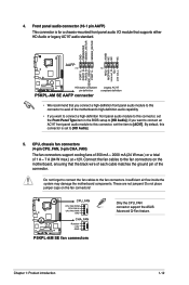
... a chassis-mounted front panel audio I/O module that you connect a high-definition front panel audio module to this connector to avail of the motherboard's high-definition audio capability. • If you want to connect a high-definition front panel audio module to this connector, set the Front...HD Audio]; Do not forget to connect the fan cables to [HD Audio]. 5. P5KPL-AM SE CPU_FAN CPU FAN PWM CPU FAN IN CPU FAN PWR GND CHA_FAN Rotation +12V GND P5KPL-AM SE fan connectors Only the CPU_FAN connector support the ASUS Advanced Q-Fan feature. Chapter 1: Product introduction 1-12
... a chassis-mounted front panel audio I/O module that you connect a high-definition front panel audio module to this connector to avail of the motherboard's high-definition audio capability. • If you want to connect a high-definition front panel audio module to this connector, set the Front...HD Audio]; Do not forget to connect the fan cables to [HD Audio]. 5. P5KPL-AM SE CPU_FAN CPU FAN PWM CPU FAN IN CPU FAN PWR GND CHA_FAN Rotation +12V GND P5KPL-AM SE fan connectors Only the CPU_FAN connector support the ASUS Advanced Q-Fan feature. Chapter 1: Product introduction 1-12
User Manual
Page 24
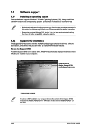
Use the setup procedures presented in your computer. To run the DVD. 1-15 ASUS P5KPL-AM SE Always install the latest OS version and corresponding updates to locate the file ASSETUP.EXE from the BIN folder. The DVD automatically displays the ... to install If Autorun is enabled in this section for better compatibility and system stability. 1.8.2 Support DVD information The Support DVD that comes with the motherboard package contains the drivers, software applications, and utilities that you install Windows® XP Service Pack 1 or later versions before installing the drivers for...
Use the setup procedures presented in your computer. To run the DVD. 1-15 ASUS P5KPL-AM SE Always install the latest OS version and corresponding updates to locate the file ASSETUP.EXE from the BIN folder. The DVD automatically displays the ... to install If Autorun is enabled in this section for better compatibility and system stability. 1.8.2 Support DVD information The Support DVD that comes with the motherboard package contains the drivers, software applications, and utilities that you install Windows® XP Service Pack 1 or later versions before installing the drivers for...
User Manual
Page 26
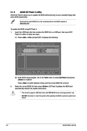
...2. 1. Go to the Tools menu to select EZ Flash 2 and press to prevent system boot failure! 2-2 ASUS P5KPL-AM SE Download the latest BIOS file for this motherboard from the ASUS website at www.asus.com. Insert the USB flash disk that contains the BIOS file to a USB port, then launch EZ Flash 2...correct BIOS file is found. 2. Press to display the following: ASUSTek EZ Flash 2 BIOS ROM Utility V3.25 FLASH TYPE: MXIC 25L8005 Current ROM BOARD: P5KPL-AM SE VER: 0309 (H:00 B:01) DATE: 09/28/2008 Update ROM BOARD: Unknown VER: Unknown DATE: Unknown PATH: A:\ A: Note [Enter] Select or Load...
...2. 1. Go to the Tools menu to select EZ Flash 2 and press to prevent system boot failure! 2-2 ASUS P5KPL-AM SE Download the latest BIOS file for this motherboard from the ASUS website at www.asus.com. Insert the USB flash disk that contains the BIOS file to a USB port, then launch EZ Flash 2...correct BIOS file is found. 2. Press to display the following: ASUSTek EZ Flash 2 BIOS ROM Utility V3.25 FLASH TYPE: MXIC 25L8005 Current ROM BOARD: P5KPL-AM SE VER: 0309 (H:00 B:01) DATE: 09/28/2008 Update ROM BOARD: Unknown VER: Unknown DATE: Unknown PATH: A:\ A: Note [Enter] Select or Load...
User Manual
Page 28
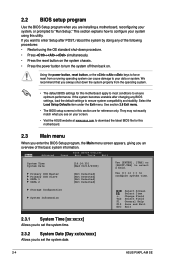
...then back on the system chassis. • Press the power button to set the system date. 2-4 ASUS P5KPL-AM SE 2.2 BIOS setup program Use the BIOS Setup program when you are for this motherboard. 2.3 Main menu When you enter the BIOS Setup program, the Main menu screen appears, giving you... an overview of the following procedures: • Restart using this motherboard apply to most conditions to ensure ...
...then back on the system chassis. • Press the power button to set the system date. 2-4 ASUS P5KPL-AM SE 2.2 BIOS setup program Use the BIOS Setup program when you are for this motherboard. 2.3 Main menu When you enter the BIOS Setup program, the Main menu screen appears, giving you... an overview of the following procedures: • Restart using this motherboard apply to most conditions to ensure ...

User Manual
Page 36
... transmit data until the computer and applications are fully running. Power On By External Modems [Disabled] Disable/Enable RI to the motherboard, the field shows N/A. This feature requires an ATX power supply that provides at least 1A on the +5VSB lead. CPU Fan Speed (RPM) [xxxxRPM] or [N/A] or [...lead. If the fan is off and then back on . Select Ignored if you do not wish to display the detected speed. 2-12 ASUS P5KPL-AM SE If the fan is not connected to generate a wake event. Select Ignored if you do not wish to display the detected temperatures. This ...
... transmit data until the computer and applications are fully running. Power On By External Modems [Disabled] Disable/Enable RI to the motherboard, the field shows N/A. This feature requires an ATX power supply that provides at least 1A on the +5VSB lead. CPU Fan Speed (RPM) [xxxxRPM] or [N/A] or [...lead. If the fan is off and then back on . Select Ignored if you do not wish to display the detected speed. 2-12 ASUS P5KPL-AM SE If the fan is not connected to generate a wake event. Select Ignored if you do not wish to display the detected temperatures. This ...


