
Motherboard Installation Guide
Page 8
These documents are also provided. • Chapter 3: Software support This chapter describes the contents of the jumpers and connectors on ASUS hardware and software products. How this guide This user guide contains the information you have been added by your dealer. This chapter also lists the ... product package may include optional documentation, such as warranty flyers, that comes with the motherboard package. Where to find more information Refer to change system settings through the BIOS Setup menus. It includes description of the support CD that may have to the...
These documents are also provided. • Chapter 3: Software support This chapter describes the contents of the jumpers and connectors on ASUS hardware and software products. How this guide This user guide contains the information you have been added by your dealer. This chapter also lists the ... product package may include optional documentation, such as warranty flyers, that comes with the motherboard package. Where to find more information Refer to change system settings through the BIOS Setup menus. It includes description of the support CD that may have to the...

Motherboard Installation Guide
Page 34
....02.49.04 V5.72.22.34.00 V009.004.001.032 V009.010.001.015 V133.A52001.102 • Set the XJ1-5 jumpers to x1 mode (pin 1-2) if your graphics card cannot run at x4 mode. • Visit the ASUS website for the latest VGA Qualified Vendors List. 1-22 Chapter 1: Product introduction
....02.49.04 V5.72.22.34.00 V009.004.001.032 V009.010.001.015 V133.A52001.102 • Set the XJ1-5 jumpers to x1 mode (pin 1-2) if your graphics card cannot run at x4 mode. • Visit the ASUS website for the latest VGA Qualified Vendors List. 1-22 Chapter 1: Product introduction

Motherboard Installation Guide
Page 35
... will cause system boot failure! ASUS P5GZ-MX 1-23 Except when clearing the RTC RAM, never remove the cap on pins 2-3 for about 5~10 seconds, then move the cap back to re-enter data. Keep the cap on CLRTC jumper default position. Hold down and ...install the battery. 5. You can automatically reset parameter settings to overclocking, use the C.P.R. (CPU Parameter Recall) feature. The onboard button cell battery powers the RAM data in CMOS. Move the jumper cap from pins 1-2 (default) to overclocking. P5GZ-MX R P5GZ-MX Clear RTC RAM CLRTC 12 23 Normal Clear CMOS...
... will cause system boot failure! ASUS P5GZ-MX 1-23 Except when clearing the RTC RAM, never remove the cap on pins 2-3 for about 5~10 seconds, then move the cap back to re-enter data. Keep the cap on CLRTC jumper default position. Hold down and ...install the battery. 5. You can automatically reset parameter settings to overclocking, use the C.P.R. (CPU Parameter Recall) feature. The onboard button cell battery powers the RAM data in CMOS. Move the jumper cap from pins 1-2 (default) to overclocking. P5GZ-MX R P5GZ-MX Clear RTC RAM CLRTC 12 23 Normal Clear CMOS...

Motherboard Installation Guide
Page 36
...-E mode slection (3-pin XJ1, XJ2, XJ3, XJ4, XJ5) These jumpers allow you set XJ1-5 to pins 2-3. 1-24 Chapter 1: Product introduction P5GZ-MX R P5GZ-MX XJ Setting XJ1-5 12 23 PCI-E x1, x1 PCI-Ex4, N/A (Default) XJ1-5 jumper setting configurations Graphics card mode Add-on card mode Integrated Graphics mode (default) Jumper Setting (XJ1~XJ5) 2-3 pin 1-2 pin PCIE x 16 slot Card type...
...-E mode slection (3-pin XJ1, XJ2, XJ3, XJ4, XJ5) These jumpers allow you set XJ1-5 to pins 2-3. 1-24 Chapter 1: Product introduction P5GZ-MX R P5GZ-MX XJ Setting XJ1-5 12 23 PCI-E x1, x1 PCI-Ex4, N/A (Default) XJ1-5 jumper setting configurations Graphics card mode Add-on card mode Integrated Graphics mode (default) Jumper Setting (XJ1~XJ5) 2-3 pin 1-2 pin PCIE x 16 slot Card type...

Motherboard Installation Guide
Page 37
... for the rear USB ports (USB port 1-4). ASUS P5GZ-MX 1-25 USB device wake-up (3-pin USBPW1-4, USBPW5-8) Set these jumpers to +5V to wake up from S1 sleep mode (CPU stopped, DRAM refreshed, system running in sleep mode. Set to +5VSB to wake up the computer from S3 and S4 sleep ...5-8) that can connect to CPU, DRAM in slow refresh, power supply in reduced power mode). USBPW1-4 12 23 +5V (Default) +5VSB USBPW5-8 P5GZ-MX 12 23 R P5GZ-MX USB Device Wake Up +5V (Default) +5VSB • The USB device wake-up . • The total current consumed must NOT exceed the ...
... for the rear USB ports (USB port 1-4). ASUS P5GZ-MX 1-25 USB device wake-up (3-pin USBPW1-4, USBPW5-8) Set these jumpers to +5V to wake up from S1 sleep mode (CPU stopped, DRAM refreshed, system running in sleep mode. Set to +5VSB to wake up the computer from S3 and S4 sleep ...5-8) that can connect to CPU, DRAM in slow refresh, power supply in reduced power mode). USBPW1-4 12 23 +5V (Default) +5VSB USBPW5-8 P5GZ-MX 12 23 R P5GZ-MX USB Device Wake Up +5V (Default) +5VSB • The USB device wake-up . • The total current consumed must NOT exceed the ...

Motherboard Installation Guide
Page 40
P5GZ-MX PRI_IDE R P5GZ-MX IDE Connector Single device Two devices Drive jumper setting Cable-Select or Master Cable-Select Master Slave Mode of the following modes to configure your device(s). 2. If any device jumper is removed to the motherboard's IDE connector, then select one of device(s) Master Slave... Cable connector Black Black Gray Black or gray • Pin 20 on the IDE connector is set as "Cable-Select," make sure all other device jumpers have the same setting. 1-28 Chapter 1: Product introduction This prevents incorrect insertion when you connect the IDE cable. &#...
P5GZ-MX PRI_IDE R P5GZ-MX IDE Connector Single device Two devices Drive jumper setting Cable-Select or Master Cable-Select Master Slave Mode of the following modes to configure your device(s). 2. If any device jumper is removed to the motherboard's IDE connector, then select one of device(s) Master Slave... Cable connector Black Black Gray Black or gray • Pin 20 on the IDE connector is set as "Cable-Select," make sure all other device jumpers have the same setting. 1-28 Chapter 1: Product introduction This prevents incorrect insertion when you connect the IDE cable. &#...
Motherboard Installation Guide
Page 45
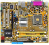
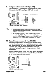
...intrusion connector (4-1 pin CHASSIS) This connector is set the Front Panel Support Type item in the BIOS to [HD Audio]. The signal is removed or replaced. P5GZ-MX +5VSB_MB Chassis Signal GND CHASSIS (Default) R P5GZ-MX Intrusion Connector ASUS P5GZ-MX 1-33 See section "2.4.6 Onboard Device Configuration"..." are shorted with a jumper cap. Azalia-compliant Legacy AC'97-compliant pin definition pin definition AGND PRESENSE# MIC2_JD HP_HD AGND NC NC NC P5GZ-MX MIC2_L MIC2_R Line out_R NC Line out_L MIC2_L MIC2_R HP_R Jack_Sense HP_L AAFP R P5GZ-MX Front Panel Audio Connector ...
...intrusion connector (4-1 pin CHASSIS) This connector is set the Front Panel Support Type item in the BIOS to [HD Audio]. The signal is removed or replaced. P5GZ-MX +5VSB_MB Chassis Signal GND CHASSIS (Default) R P5GZ-MX Intrusion Connector ASUS P5GZ-MX 1-33 See section "2.4.6 Onboard Device Configuration"..." are shorted with a jumper cap. Azalia-compliant Legacy AC'97-compliant pin definition pin definition AGND PRESENSE# MIC2_JD HP_HD AGND NC NC NC P5GZ-MX MIC2_L MIC2_R Line out_R NC Line out_L MIC2_L MIC2_R HP_R Jack_Sense HP_L AAFP R P5GZ-MX Front Panel Audio Connector ...

Motherboard Installation Guide
Page 80
...password, select the Change Supervisor Password then press . If you to change the supervisor password, follow the same steps as in setting a user password. Select an item then press to disabled password. Confirm the password when prompted. The message "Password Uninstalled" ...appears. Change Option F1 General Help Select this item to set or change password. To change the system security settings. See section "2.6 Jumpers" for information on top of at least six letters and/or numbers, then press . 3. ...
...password, select the Change Supervisor Password then press . If you to change the supervisor password, follow the same steps as in setting a user password. Select an item then press to disabled password. Confirm the password when prompted. The message "Password Uninstalled" ...appears. Change Option F1 General Help Select this item to set or change password. To change the system security settings. See section "2.6 Jumpers" for information on top of at least six letters and/or numbers, then press . 3. ...

P5GZ-MX User Manual 2nd edition for English Edition
Page 8
... This chapter describes the features of the jumpers and connectors on ASUS hardware and software products. Detailed descriptions of the BIOS parameters are not part of the support CD that comes with the motherboard package. Optional documentation Your product package may have to change system settings through the BIOS Setup menus. viii This...
... This chapter describes the features of the jumpers and connectors on ASUS hardware and software products. Detailed descriptions of the BIOS parameters are not part of the support CD that comes with the motherboard package. Optional documentation Your product package may have to change system settings through the BIOS Setup menus. viii This...

P5GZ-MX User Manual 2nd edition for English Edition
Page 34
... WinFast PX7800GTX TDH 256MB - Leadtek Quadro FX540 128M - Leadtek Quadro FX1400 128M - Powercolor Radeon X1800XT - • Set the XJ1-5 jumpers to x1 mode (pin 1-2) if your graphics card cannot run at x4 mode. • Visit the ASUS website for the latest VGA Qualified Vendors List. 1-22 Chapter 1: Product introduction Matrox Parhelia APVe 128M...
... WinFast PX7800GTX TDH 256MB - Leadtek Quadro FX540 128M - Leadtek Quadro FX1400 128M - Powercolor Radeon X1800XT - • Set the XJ1-5 jumpers to x1 mode (pin 1-2) if your graphics card cannot run at x4 mode. • Visit the ASUS website for the latest VGA Qualified Vendors List. 1-22 Chapter 1: Product introduction Matrox Parhelia APVe 128M...

P5GZ-MX User Manual 2nd edition for English Edition
Page 35
... 1. 2. 3. 4. 5. 6. ASUS P5GZ-MX 1-23 Remove the onboard battery. Re-install the battery. Except when clearing the RTC RAM, never remove the cap on pins 2-3 for about 5~10 seconds, then move the cap back to pins 1-2. You can automatically reset parameter settings to re-enter data. The onboard...the computer. Removing the cap will cause system boot failure! P5GZ-MX CLRTC 1 2 2 3 Clear CMOS R P5GZ-MX Clear RTC RAM Normal (Default) You do not need to clear the RTC when the system hangs due to pins 2-3. 1.9 Jumpers 1. For system failure due to clear the Real Time Clock...
... 1. 2. 3. 4. 5. 6. ASUS P5GZ-MX 1-23 Remove the onboard battery. Re-install the battery. Except when clearing the RTC RAM, never remove the cap on pins 2-3 for about 5~10 seconds, then move the cap back to pins 1-2. You can automatically reset parameter settings to re-enter data. The onboard...the computer. Removing the cap will cause system boot failure! P5GZ-MX CLRTC 1 2 2 3 Clear CMOS R P5GZ-MX Clear RTC RAM Normal (Default) You do not need to clear the RTC when the system hangs due to pins 2-3. 1.9 Jumpers 1. For system failure due to clear the Real Time Clock...

P5GZ-MX User Manual 2nd edition for English Edition
Page 36
... 2-3. 1-24 Chapter 1: Product introduction Refer to adjust the operating speed of PCIE x1 and PCIE x16 slots. P5GZ-MX XJ1-5 1 2 2 3 PCI-E x1, x1 PCI-Ex4, N/A (Default) R P5GZ-MX XJ Setting XJ1-5 jumper setting configurations Graphics card mode Add-on card mode Jumper Setting (XJ1~XJ5) 2-3 pin PCIE x 16 slot Card type PCIe graphics card or other PCIe x8/x4...
... 2-3. 1-24 Chapter 1: Product introduction Refer to adjust the operating speed of PCIE x1 and PCIE x16 slots. P5GZ-MX XJ1-5 1 2 2 3 PCI-E x1, x1 PCI-Ex4, N/A (Default) R P5GZ-MX XJ Setting XJ1-5 jumper setting configurations Graphics card mode Add-on card mode Jumper Setting (XJ1~XJ5) 2-3 pin PCIE x 16 slot Card type PCIe graphics card or other PCIe x8/x4...

P5GZ-MX User Manual 2nd edition for English Edition
Page 37
USB device wake-up (3-pin USBPW1-4, USBPW5-8) Set these jumpers to +5V to wake up from S1 sleep mode (CPU stopped, DRAM refreshed, system running in sleep mode. USBPW1-4 1 2 2 3 P5GZ-MX +5V (Default) +5VSB USBPW5-8 1 2 R P5GZ-MX USB Device Wake Up +5V (Default) • The USB...ASUS P5GZ-MX 2 3 +5VSB 1-25 The USBPW1-4 jumper is for the internal USB connectors (USB port 5-8) that can connect to wake up the computer from S3 and S4 sleep modes (no power to CPU, DRAM in slow refresh, power supply in reduced power mode). The USBPW5-8 jumper is for each USB port; Set...
USB device wake-up (3-pin USBPW1-4, USBPW5-8) Set these jumpers to +5V to wake up from S1 sleep mode (CPU stopped, DRAM refreshed, system running in sleep mode. USBPW1-4 1 2 2 3 P5GZ-MX +5V (Default) +5VSB USBPW5-8 1 2 R P5GZ-MX USB Device Wake Up +5V (Default) • The USB...ASUS P5GZ-MX 2 3 +5VSB 1-25 The USBPW1-4 jumper is for the internal USB connectors (USB port 5-8) that can connect to wake up the computer from S3 and S4 sleep modes (no power to CPU, DRAM in slow refresh, power supply in reduced power mode). The USBPW5-8 jumper is for each USB port; Set...
P5GZ-MX User Manual 2nd edition for English Edition
Page 45
... removed or replaced. By default, the pins labeled "Chassis Signal" and "Ground" are shorted with a jumper cap. P5GZ-MX CHASSIS (Default) R P5GZ-MX Intrusion Connector ASUS P5GZ-MX 1-33 Chassis Signal GND +5VSB_MB NC Chassis intrusion connector (4-1 pin CHASSIS) This connector is set the Front Panel Support Type item in the BIOS to this connector is for details. 10...
... removed or replaced. By default, the pins labeled "Chassis Signal" and "Ground" are shorted with a jumper cap. P5GZ-MX CHASSIS (Default) R P5GZ-MX Intrusion Connector ASUS P5GZ-MX 1-33 Chassis Signal GND +5VSB_MB NC Chassis intrusion connector (4-1 pin CHASSIS) This connector is set the Front Panel Support Type item in the BIOS to this connector is for details. 10...

P5GZ-MX User Manual 2nd edition for English Edition
Page 80
... Password User Password : Not Installed : Not Installed to display the configuration options. To set to [Enabled], this function allows the option ROMs to erase the RTC RAM. 2-34 Chapter 2: BIOS setup See section "2.6 Jumpers" for information on top of at least six letters and/or numbers, then press . Change Supervisor Password Change...
... Password User Password : Not Installed : Not Installed to display the configuration options. To set to [Enabled], this function allows the option ROMs to erase the RTC RAM. 2-34 Chapter 2: BIOS setup See section "2.6 Jumpers" for information on top of at least six letters and/or numbers, then press . Change Supervisor Password Change...


