
User Manual
Page 1
Motherboard P5G41T-M LX3
Motherboard P5G41T-M LX3
User Manual
Page 3
Contents Notices...vi Safety information vii About this guide vii P5G41T-M LX3 specifications summary ix Chapter 1: Product introduction 1.1 Welcome 1-1 1.2 Package contents 1-1 1.3 Special features 1-1 1.3.1 Product highlights 1-1 1.3.2 Innovative ASUS features 1-2 1.4 Before you proceed 1-4 1.5 Motherboard overview 1-5 1.5.1 Placement direction 1-5 1.5.2 Screw holes 1-5 1.5.3 Motherboard layout 1-6 1.5.4 Layout contents 1-6 1.6 Central Processing Unit (CPU 1-7 1.6.1 Installing the CPU 1-7 1.6.2 Installing the CPU heatsink and fan 1-10 1.6.3 Uninstalling...
Contents Notices...vi Safety information vii About this guide vii P5G41T-M LX3 specifications summary ix Chapter 1: Product introduction 1.1 Welcome 1-1 1.2 Package contents 1-1 1.3 Special features 1-1 1.3.1 Product highlights 1-1 1.3.2 Innovative ASUS features 1-2 1.4 Before you proceed 1-4 1.5 Motherboard overview 1-5 1.5.1 Placement direction 1-5 1.5.2 Screw holes 1-5 1.5.3 Motherboard layout 1-6 1.5.4 Layout contents 1-6 1.6 Central Processing Unit (CPU 1-7 1.6.1 Installing the CPU 1-7 1.6.2 Installing the CPU heatsink and fan 1-10 1.6.3 Uninstalling...
User Manual
Page 6
...should not be placed in a particular installation. The use of shielded cables for disposal of the FCC Rules. DO NOT throw the motherboard in a residential installation. This product has been designed to provide reasonable protection against harmful interference in municipal waste. This symbol of parts ...interference will not occur in municipal waste. DO NOT throw the mercury-containing button cell battery in our products at ASUS REACH website at http://csr.asus.com/english/REACH.htm. Operation is connected. • Consult the dealer or an experienced radio/TV technician for ...
...should not be placed in a particular installation. The use of shielded cables for disposal of the FCC Rules. DO NOT throw the motherboard in a residential installation. This product has been designed to provide reasonable protection against harmful interference in municipal waste. This symbol of parts ...interference will not occur in municipal waste. DO NOT throw the mercury-containing button cell battery in our products at ASUS REACH website at http://csr.asus.com/english/REACH.htm. Operation is connected. • Consult the dealer or an experienced radio/TV technician for ...
User Manual
Page 7
...; Chapter 1: Product introduction This chapter describes the features of the BIOS parameters are not damaged. vii Operation safety • Before installing the motherboard and adding devices on a stable surface. • If you encounter technical problems with the package. • Before using , contact your ... technician or your retailer. If you are using the product, ensure that all power cables are connected. Detailed descriptions of the motherboard and the new technology it supports. • Chapter 2: BIOS information This chapter tells how to fix it , carefully read all...
...; Chapter 1: Product introduction This chapter describes the features of the BIOS parameters are not damaged. vii Operation safety • Before installing the motherboard and adding devices on a stable surface. • If you encounter technical problems with the package. • Before using , contact your ... technician or your retailer. If you are using the product, ensure that all power cables are connected. Detailed descriptions of the motherboard and the new technology it supports. • Chapter 2: BIOS information This chapter tells how to fix it , carefully read all...
User Manual
Page 11
...® CPUs in your package with the list below. 1.2 Package contents Check your motherboard package for the following items. Motherboard Cables Accessories Application DVD Documentation ASUS P5G41T-M LX3 motherboard 2 x Serial ATA 3.0Gb/s cables 1 x I/O shield ASUS motherboard support DVD User Manual If any of ASUS quality motherboards! Before you for multitasking, multimedia, and enthusiastic gamers with 1333/1066 MHz FSB. Thank...
...® CPUs in your package with the list below. 1.2 Package contents Check your motherboard package for the following items. Motherboard Cables Accessories Application DVD Documentation ASUS P5G41T-M LX3 motherboard 2 x Serial ATA 3.0Gb/s cables 1 x I/O shield ASUS motherboard support DVD User Manual If any of ASUS quality motherboards! Before you for multitasking, multimedia, and enthusiastic gamers with 1333/1066 MHz FSB. Thank...

User Manual
Page 12
... according to system load and temperature, enabling users to provide efficient power management for advanced operating systems. Innovative ASUS features ASUS EPU ASUS EPU (Energy Processing Unit) provides total system power management by detecting the current PC loading and intelligently moderating ... provides the most appropriate power usage to convert your favorite photo into an overclocking button. Serial ATA 3Gb/s technology This motherboard supports hard drives based on your screen. 1-2 Chapter 1: Product introduction Gigabit LAN solution The onboard LAN controller is designed...
... according to system load and temperature, enabling users to provide efficient power management for advanced operating systems. Innovative ASUS features ASUS EPU ASUS EPU (Energy Processing Unit) provides total system power management by detecting the current PC loading and intelligently moderating ... provides the most appropriate power usage to convert your favorite photo into an overclocking button. Serial ATA 3Gb/s technology This motherboard supports hard drives based on your screen. 1-2 Chapter 1: Product introduction Gigabit LAN solution The onboard LAN controller is designed...
User Manual
Page 13
... to update the BIOS without using an OS-based utility. ASUS P5G41T-M LX3 1-3 Simply shut down and reboot the system, and the BIOS automatically restores the CPU parameters to energy consumptions. ErP ready The motherboard is a utility that contains the latest BIOS file. C.P.R. ...(CPU Parameter Recall) The BIOS C.P.R. ASUS EZ Flash 2 ASUS EZ Flash 2 is European Union´s Energy-related Products (ErP) ready,...
... to update the BIOS without using an OS-based utility. ASUS P5G41T-M LX3 1-3 Simply shut down and reboot the system, and the BIOS automatically restores the CPU parameters to energy consumptions. ErP ready The motherboard is a utility that contains the latest BIOS file. C.P.R. ...(CPU Parameter Recall) The BIOS C.P.R. ASUS EZ Flash 2 ASUS EZ Flash 2 is European Union´s Energy-related Products (ErP) ready,...
User Manual
Page 14
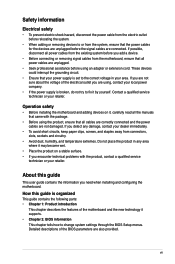
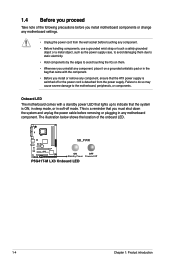
...LED that lights up to the motherboard, peripherals, or components. SB_PWR P5G41T-M LX3 ON OFF Standby Power Powered Off P5G41T-M LX3 Onboard LED 1-4 Chapter 1: Product introduction Onboard LED The motherboard comes with the component. • Before you install or remove any motherboard component. The illustration below shows ... to indicate that you must shut down the system and unplug the power cable before you install motherboard components or change any motherboard settings. • Unplug the power cord from the power supply. 1.4 Before you proceed Take note of the...
...LED that lights up to the motherboard, peripherals, or components. SB_PWR P5G41T-M LX3 ON OFF Standby Power Powered Off P5G41T-M LX3 Onboard LED 1-4 Chapter 1: Product introduction Onboard LED The motherboard comes with the component. • Before you install or remove any motherboard component. The illustration below shows ... to indicate that you must shut down the system and unplug the power cable before you install motherboard components or change any motherboard settings. • Unplug the power cord from the power supply. 1.4 Before you proceed Take note of the...
User Manual
Page 15
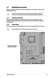
... holes Place six screws into the chassis in the correct orientation. 1.5 Motherboard overview Before you install the motherboard, study the configuration of your chassis to ensure that the motherboard fits into it into the holes indicated by circles to secure the motherboard to the chassis. Place this side towards the rear of the chassis P5G41T-M LX3 ASUS P5G41T-M LX3 1-5
... holes Place six screws into the chassis in the correct orientation. 1.5 Motherboard overview Before you install the motherboard, study the configuration of your chassis to ensure that the motherboard fits into it into the holes indicated by circles to secure the motherboard to the chassis. Place this side towards the rear of the chassis P5G41T-M LX3 ASUS P5G41T-M LX3 1-5
User Manual
Page 16
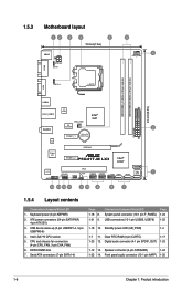
1.5.3 Motherboard layout 12 3 4 5 18.8cm(7.4in) KBMS ATX12V KBPWR 6 5 CPU_FAN COM1 USBPW1-4 LGA775 DDR3 DIMM_A1 (64bit, 240-pin module) DDR3 DIMM_B1 (64bit, 240-pin module) VGA USB34 24.4cm(9.6in) LAN1_USB12 RTL 8103EL CHA_FAN Intel® G41 ICS AUDIO 9LRS954 2 PCIEX1_1 Lithium Cell CMOS Power EATXPWR ATHEROS 8151 Super I/O PCIEX16 PCIEX1_2 P5G41T-M LX3 Intel...
1.5.3 Motherboard layout 12 3 4 5 18.8cm(7.4in) KBMS ATX12V KBPWR 6 5 CPU_FAN COM1 USBPW1-4 LGA775 DDR3 DIMM_A1 (64bit, 240-pin module) DDR3 DIMM_B1 (64bit, 240-pin module) VGA USB34 24.4cm(9.6in) LAN1_USB12 RTL 8103EL CHA_FAN Intel® G41 ICS AUDIO 9LRS954 2 PCIEX1_1 Lithium Cell CMOS Power EATXPWR ATHEROS 8151 Super I/O PCIEX16 PCIEX1_2 P5G41T-M LX3 Intel...
User Manual
Page 17
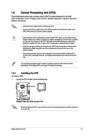
... the motherboard, ensure that the cam box is facing towards you and the load lever is on your retailer immediately if the PnP cap is missing, or if you see any damage to the socket contacts resulting from incorrect CPU installation/removal, or misplacement/loss/incorrect removal of the PnP cap. ASUS P5G41T-M LX3 1-7
... the motherboard, ensure that the cam box is facing towards you and the load lever is on your retailer immediately if the PnP cap is missing, or if you see any damage to the socket contacts resulting from incorrect CPU installation/removal, or misplacement/loss/incorrect removal of the PnP cap. ASUS P5G41T-M LX3 1-7
User Manual
Page 20
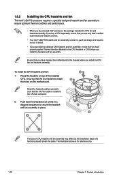
...design and requires no tool to install. • If you purchased a separate CPU heatsink and fan assembly, ensure that you have installed the motherboard to ensure optimum thermal condition and performance. • When you use only Intel®‑certified multi‑directional heatsink and fan. •...heatsink or CPU before you have properly applied Thermal Interface Material to the CPU fan connector. 2. Place the heatsink on the motherboard. Orient the heatsink and fan assembly such that you install the CPU fan and heatsink assembly. To install the CPU heatsink and fan...
...design and requires no tool to install. • If you purchased a separate CPU heatsink and fan assembly, ensure that you have installed the motherboard to ensure optimum thermal condition and performance. • When you use only Intel®‑certified multi‑directional heatsink and fan. •...heatsink or CPU before you have properly applied Thermal Interface Material to the CPU fan connector. 2. Place the heatsink on the motherboard. Orient the heatsink and fan assembly such that you install the CPU fan and heatsink assembly. To install the CPU heatsink and fan...

User Manual
Page 21
3. A A B B B A B A ASUS P5G41T-M LX3 1-11 Connect the CPU fan cable to disengage the heatsink and fan assembly from the connector on the motherboard labeled CPU_FAN. CPU_FAN CPU FAN PWM CPU FAN IN CPU FAN PWR GND P5G41T-M LX3 P5G41T-M LX3 CPU fan connector Do not forget to plug this connector. 1.6.3 Uninstalling the CPU heatsink and fan To uninstall the CPU...
3. A A B B B A B A ASUS P5G41T-M LX3 1-11 Connect the CPU fan cable to disengage the heatsink and fan assembly from the connector on the motherboard labeled CPU_FAN. CPU_FAN CPU FAN PWM CPU FAN IN CPU FAN PWR GND P5G41T-M LX3 P5G41T-M LX3 CPU fan connector Do not forget to plug this connector. 1.6.3 Uninstalling the CPU heatsink and fan To uninstall the CPU...

User Manual
Page 22
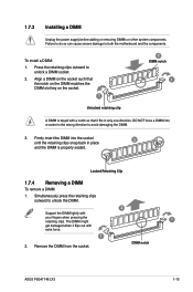
4. Rotate each fastener clockwise to ensure correct orientation when reinstalling. 1.7 System memory 1.7.1 Overview The motherboard comes with two Double Data Rate 3 (DDR3) Dual Inline Memory Modules (DIMM) sockets. The figure illustrates the location of the DDR3 DIMM sockets: DIMM_A1 DIMM_B1 P5G41T-M LX3 Channel Channel A Channel B P5G41T-M LX3 240-pin DDR3 DIMM sockets Sockets DIMM_A1 DIMM_B1 1-12 Chapter 1: Product introduction Carefully remove the heatsink and fan assembly from the motherboard. 5.
4. Rotate each fastener clockwise to ensure correct orientation when reinstalling. 1.7 System memory 1.7.1 Overview The motherboard comes with two Double Data Rate 3 (DDR3) Dual Inline Memory Modules (DIMM) sockets. The figure illustrates the location of the DDR3 DIMM sockets: DIMM_A1 DIMM_B1 P5G41T-M LX3 Channel Channel A Channel B P5G41T-M LX3 240-pin DDR3 DIMM sockets Sockets DIMM_A1 DIMM_B1 1-12 Chapter 1: Product introduction Carefully remove the heatsink and fan assembly from the motherboard. 5.
User Manual
Page 23
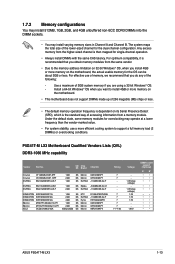
...8226; • • • • • • • • • • • • ASUS P5G41T-M LX3 1-13 For effective use a more memory on the motherboard. • This motherboard does not support DIMMs made up of 256 megabits (Mb) chips or less. • The default memory operation frequency is... dependent on the motherboard, the actual usable memory for the OS can be about 3GB or less. P5G41T-M LX3 Motherboard Qualified Vendors Lists (QVL) DDR3-1066 MHz capability Vendor Part No. Use ...
...8226; • • • • • • • • • • • • ASUS P5G41T-M LX3 1-13 For effective use a more memory on the motherboard. • This motherboard does not support DIMMs made up of 256 megabits (Mb) chips or less. • The default memory operation frequency is... dependent on the motherboard, the actual usable memory for the OS can be about 3GB or less. P5G41T-M LX3 Motherboard Qualified Vendors Lists (QVL) DDR3-1066 MHz capability Vendor Part No. Use ...
User Manual
Page 25
Press the retaining clips outward to both the motherboard and the components. Firmly insert the DIMM into a socket in the wrong direction to unlock the DIMM. 2 Support the DIMM lightly with a notch so that .... The DIMM might 1 get damaged when it fits in place 3 and the DIMM is keyed with your fingers when pressing the retaining clips. DIMM notch ASUS P5G41T-M LX3 1-15 Locked Retaining Clip 1.7.4 Removing a DIMM To remove a DIMM: 1. DO NOT force a DIMM into the socket until the retaining clips snap back in only one...
Press the retaining clips outward to both the motherboard and the components. Firmly insert the DIMM into a socket in the wrong direction to unlock the DIMM. 2 Support the DIMM lightly with a notch so that .... The DIMM might 1 get damaged when it fits in place 3 and the DIMM is keyed with your fingers when pressing the retaining clips. DIMM notch ASUS P5G41T-M LX3 1-15 Locked Retaining Clip 1.7.4 Removing a DIMM To remove a DIMM: 1. DO NOT force a DIMM into the socket until the retaining clips snap back in only one...
User Manual
Page 26
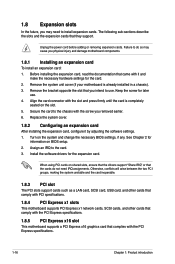
... "Share IRQ" or that came with the PCI Express specifications. 1-16 Chapter 1: Product introduction Remove the system unit cover (if your motherboard is completely seated on BIOS setup. 2. Secure the card to use . 4. Assign an IRQ to install expansion cards. Remove the bracket...Install the software drivers for information on the slot. 5. 1.8 Expansion slots In the future, you may cause you physical injury and damage motherboard components. 1.8.1 Installing an expansion card To install an expansion card: 1. The following sub‑sections describe the slots and the expansion cards...
... "Share IRQ" or that came with the PCI Express specifications. 1-16 Chapter 1: Product introduction Remove the system unit cover (if your motherboard is completely seated on BIOS setup. 2. Secure the card to use . 4. Assign an IRQ to install expansion cards. Remove the bracket...Install the software drivers for information on the slot. 5. 1.8 Expansion slots In the future, you may cause you physical injury and damage motherboard components. 1.8.1 Installing an expansion card To install an expansion card: 1. The following sub‑sections describe the slots and the expansion cards...
User Manual
Page 30
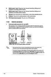
...of the front panel audio I /O module that you connect a high-definition front panel audio module to this connector to avail of the motherboard's high-definition audio capability. • If you want to connect a high-definition front panel audio module to [AC97]. These two 4-pin...PIN 1 PIN 1 MIC2 MICPWR Line out_R NC Line out_L PORT1 L PORT1 R PORT2 R SENSE_SEND PORT2 L P5G41T-M LX3 HD-audio-compliant Legacy AC'97 pin definition compliant definition P5G41T-M LX3 Front panel audio connector • We recommend that supports either HD Audio or legacy AC`97 audio standard. ...
...of the front panel audio I /O module that you connect a high-definition front panel audio module to this connector to avail of the motherboard's high-definition audio capability. • If you want to connect a high-definition front panel audio module to [AC97]. These two 4-pin...PIN 1 PIN 1 MIC2 MICPWR Line out_R NC Line out_L PORT1 L PORT1 R PORT2 R SENSE_SEND PORT2 L P5G41T-M LX3 HD-audio-compliant Legacy AC'97 pin definition compliant definition P5G41T-M LX3 Front panel audio connector • We recommend that supports either HD Audio or legacy AC`97 audio standard. ...
User Manual
Page 32
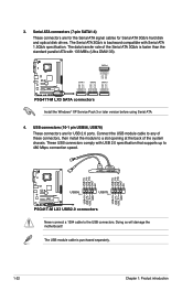
... GND GND RSATA_RXN2 RSATA_RXP2 GND RSATA_TXN2 RSATA_TXP2 GND GND RSATA_RXN3 RSATA_RXP3 GND RSATA_TXN3 RSATA_TXP3 GND P5G41T-M LX3 SATA1 SATA2 SATA3 P5G41T-M LX3 SATA connectors Install the Windows® XP Service Pack 3 or later version before using...motherboard! USB connectors (10-1 pin USB56, USB78) These connectors are for the Serial ATA signal cables for USB 2.0 ports. The Serial ATA 3Gb/s is purchased separately. 1-22 Chapter 1: Product introduction USB+5V USB_P8USB_P8+ GND NC USB+5V USB_P6USB_P6+ GND NC USB+5V USB_P7USB_P7+ GND USB+5V USB_P5USB_P5+ GND P5G41T-M LX3...
... GND GND RSATA_RXN2 RSATA_RXP2 GND RSATA_TXN2 RSATA_TXP2 GND GND RSATA_RXN3 RSATA_RXP3 GND RSATA_TXN3 RSATA_TXP3 GND P5G41T-M LX3 SATA1 SATA2 SATA3 P5G41T-M LX3 SATA connectors Install the Windows® XP Service Pack 3 or later version before using...motherboard! USB connectors (10-1 pin USB56, USB78) These connectors are for the Serial ATA signal cables for USB 2.0 ports. The Serial ATA 3Gb/s is purchased separately. 1-22 Chapter 1: Product introduction USB+5V USB_P8USB_P8+ GND NC USB+5V USB_P6USB_P6+ GND NC USB+5V USB_P7USB_P7+ GND USB+5V USB_P5USB_P5+ GND P5G41T-M LX3...
User Manual
Page 33
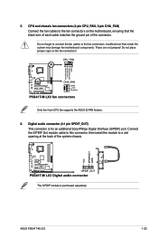
... the system may damage the motherboard components. These are not jumpers! Digital audio connector (4-1 pin SPDIF_OUT) This connector is purchased separately. CPU_FAN CPU FAN PWM CPU FAN IN CPU FAN PWR GND P5G41T-M LX3 CHA_FAN GND +12V Rotation P5G41T-M LX3 fan connectors Only the 4-pin CPU fan supports the ASUS Q-FAN feature. 6. ASUS P5G41T-M LX3 1-23 CPU and chassis...
... the system may damage the motherboard components. These are not jumpers! Digital audio connector (4-1 pin SPDIF_OUT) This connector is purchased separately. CPU_FAN CPU FAN PWM CPU FAN IN CPU FAN PWR GND P5G41T-M LX3 CHA_FAN GND +12V Rotation P5G41T-M LX3 fan connectors Only the 4-pin CPU fan supports the ASUS Q-FAN feature. 6. ASUS P5G41T-M LX3 1-23 CPU and chassis...


