User Manual
Page 3
Contents Notices...v Safety information vi About this guide vii P5G41-M LX specifications summary viii Chapter 1: Product introduction 1.1 Before you proceed 1-1 1.2 Motherboard overview 1-2 1.2.1 Motherboard layout 1-2 1.2.2 Layout contents 1-2 1.3 Central Processing... Internal connectors 1-12 1.8 Software support 1-16 1.8.1 Installing an operating system 1-16 1.8.2 Support DVD information 1-16 Chapter 2: BIOS information 2.1 Managing and updating your BIOS 2-1 2.1.1 ASUS Update utility 2-1 2.1.2 ASUS EZ Flash 2 2-2 2.1.3 ASUS CrashFree BIOS 2-3 2.2 BIOS setup program 2-3 iii
Contents Notices...v Safety information vi About this guide vii P5G41-M LX specifications summary viii Chapter 1: Product introduction 1.1 Before you proceed 1-1 1.2 Motherboard overview 1-2 1.2.1 Motherboard layout 1-2 1.2.2 Layout contents 1-2 1.3 Central Processing... Internal connectors 1-12 1.8 Software support 1-16 1.8.1 Installing an operating system 1-16 1.8.2 Support DVD information 1-16 Chapter 2: BIOS information 2.1 Managing and updating your BIOS 2-1 2.1.1 ASUS Update utility 2-1 2.1.2 ASUS EZ Flash 2 2-2 2.1.3 ASUS CrashFree BIOS 2-3 2.2 BIOS setup program 2-3 iii
User Manual
Page 7
...you MUST follow to complete a task. Example: means that you must press the Enter or Return key. ASUS websites The ASUS website provides updated information on ASUS hardware and software products. If you must press the enclosed key. CAUTION: Information to prevent damage to ...8226; Chapter 1: Product introduction This chapter describes the features of the motherboard and the new technology it supports. • Chapter 2: BIOS information This chapter tells how to emphasize a word or a phrase. How this guide is organized This guide contains the following sources for...
...you MUST follow to complete a task. Example: means that you must press the Enter or Return key. ASUS websites The ASUS website provides updated information on ASUS hardware and software products. If you must press the enclosed key. CAUTION: Information to prevent damage to ...8226; Chapter 1: Product introduction This chapter describes the features of the motherboard and the new technology it supports. • Chapter 2: BIOS information This chapter tells how to emphasize a word or a phrase. How this guide is organized This guide contains the following sources for...
User Manual
Page 8
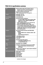
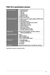
...PCIe 10/100Mbps ALC662-VC1 High Definition Audio 6-channel CODEC - Supports RGB with max. P5G41-M LX specifications summary CPU Chipset Front Side Bus Memory Graphics Expansion slots Storage LAN Audio USB ASUS special features LGA775 socket for Intel® Core™2 Quad / Core™2 Extreme ...multi-core CPU * Refer to 8 x USB 2.0/1.1 ports (4 ports at mid-board, 4 ports at back panel) ASUS CrashFree BIOS 3 ASUS Q-Fan ASUS EZ Flash 2 ASUS MyLogo 2 ASUS AI NET 2 ASUS Turbo Key (continued on the next page) viii resolution of 4GB capacity or more, Windows® 32-bit operating ...
...PCIe 10/100Mbps ALC662-VC1 High Definition Audio 6-channel CODEC - Supports RGB with max. P5G41-M LX specifications summary CPU Chipset Front Side Bus Memory Graphics Expansion slots Storage LAN Audio USB ASUS special features LGA775 socket for Intel® Core™2 Quad / Core™2 Extreme ...multi-core CPU * Refer to 8 x USB 2.0/1.1 ports (4 ports at mid-board, 4 ports at back panel) ASUS CrashFree BIOS 3 ASUS Q-Fan ASUS EZ Flash 2 ASUS MyLogo 2 ASUS AI NET 2 ASUS Turbo Key (continued on the next page) viii resolution of 4GB capacity or more, Windows® 32-bit operating ...
User Manual
Page 9
P5G41-M LX specifications summary Back panel I/O ports Internal I/O connectors BIOS features Support DVD contents Accessories Form factor 1 x PS/2 keyboard port 1 x PS/2 mouse port 1 x COM port 1 x VGA port 1 x LAN (RJ-45) port 4 x USB 2.0/1.1 ports 6-channel... connector 1 x Chassis fan connector 1 x 24-pin EATX power connector 1 x 4-pin ATX 12V power connector 8Mb Flash ROM, AMI BIOS, PnP, DMI 2.0, WfM 2.0, ACPI v2.0a, SM BIOS v2.5 Drivers ASUS PC Probe II ASUS LiveUpdate Utility Anti-virus software (OEM version) 2 x Serial ATA cables 1 x UltraDMA 100/66 cable 1 x I/O shield User Manual ...
P5G41-M LX specifications summary Back panel I/O ports Internal I/O connectors BIOS features Support DVD contents Accessories Form factor 1 x PS/2 keyboard port 1 x PS/2 mouse port 1 x COM port 1 x VGA port 1 x LAN (RJ-45) port 4 x USB 2.0/1.1 ports 6-channel... connector 1 x Chassis fan connector 1 x 24-pin EATX power connector 1 x 4-pin ATX 12V power connector 8Mb Flash ROM, AMI BIOS, PnP, DMI 2.0, WfM 2.0, ACPI v2.0a, SM BIOS v2.5 Drivers ASUS PC Probe II ASUS LiveUpdate Utility Anti-virus software (OEM version) 2 x Serial ATA cables 1 x UltraDMA 100/66 cable 1 x I/O shield User Manual ...
User Manual
Page 11
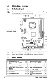
...® G41 24.4cm(9.6in) EATXPWR AUDIO 2 RTL 8103EL PCIEX16 ICS 9LRS954 7 Super I/O PCIEX1_1 Lithium Cell CMOS Power Intel® 8 ICH7 PCIEX1_2 P5G41-M LX SATA2 SATA4 CLRTC 8Mb 8 BIOS ALC PCI1 SATA1 SATA3 662-VC1 SB_PWR F_PANEL USBPW5-8 USB78 USB56 PRI_IDE AAFP SPEAKER 14 13 12 11 4 10 9 Place six screws into...
...® G41 24.4cm(9.6in) EATXPWR AUDIO 2 RTL 8103EL PCIEX16 ICS 9LRS954 7 Super I/O PCIEX1_1 Lithium Cell CMOS Power Intel® 8 ICH7 PCIEX1_2 P5G41-M LX SATA2 SATA4 CLRTC 8Mb 8 BIOS ALC PCI1 SATA1 SATA3 662-VC1 SB_PWR F_PANEL USBPW5-8 USB78 USB56 PRI_IDE AAFP SPEAKER 14 13 12 11 4 10 9 Place six screws into...
User Manual
Page 17
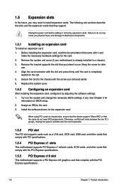
... the documentation that the cards do so may need IRQ assignments. Install the software drivers for information on the system and change the necessary BIOS settings, if any. Replace the system cover. 1.5.2 Configuring an expansion card After installing the expansion card, configure it and make the necessary... 1. Failure to do not need to the chassis with it by adjusting the software settings. 1. Keep the screw for the card. 2. Turn on BIOS setup. 2. See Chapter 2 for the expansion card. Assign an IRQ to use . 4. The following sub‑sections describe the slots and the ...
... the documentation that the cards do so may need IRQ assignments. Install the software drivers for information on the system and change the necessary BIOS settings, if any. Replace the system cover. 1.5.2 Configuring an expansion card After installing the expansion card, configure it and make the necessary... 1. Failure to do not need to the chassis with it by adjusting the software settings. 1. Keep the screw for the card. 2. Turn on BIOS setup. 2. See Chapter 2 for the expansion card. Assign an IRQ to use . 4. The following sub‑sections describe the slots and the ...
User Manual
Page 18
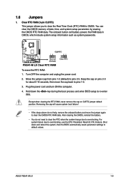
... and unplug the power cord. 2. The onboard button cell battery powers the RAM data in CMOS. Keep the cap on CLRTC jumper default position. ASUS P5G41-M LX 1-9 For system failure due to clear the CMOS RTC RAM data. Removing the cap will cause system boot failure! • If the ... • You do not help, remove the onboard battery and move the cap back to default values. Hold down and reboot the system, then the BIOS automatically resets parameter settings to pins 1-2. 3. To erase the RTC RAM: 1. Except when clearing the RTC RAM, never remove the cap on pins 2-3...
... and unplug the power cord. 2. The onboard button cell battery powers the RAM data in CMOS. Keep the cap on CLRTC jumper default position. ASUS P5G41-M LX 1-9 For system failure due to clear the CMOS RTC RAM data. Removing the cap will cause system boot failure! • If the ... • You do not help, remove the onboard battery and move the cap back to default values. Hold down and reboot the system, then the BIOS automatically resets parameter settings to pins 1-2. 3. To erase the RTC RAM: 1. Except when clearing the RTC RAM, never remove the cap on pins 2-3...
User Manual
Page 19
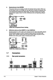
...the keyboard wake-up the computer from S3 and S4 sleep modes (no power to CPU, DRAM in slow refresh, power supply in the BIOS. Set to +5VSB to wake up feature. USB device wake-up (3-pin USBPW1-4, 3-pin USBPW5-8) Set these jumpers to +5V to ... by pressing a key on the +5VSB lead, and a corresponding setting in reduced power mode). USBPW1-4 12 23 +5V +5VSB (Default) USBPW5-8 12 23 P5G41-M LX +5V +5VSB (Default) P5G41-M LX USB Device Wake Up 1.7 Connectors 1.7.1 Rear panel connectors 1 2 34 10 9 1-10 8 7 6 5 Chapter 1: Product introduction KBPWR 12 23 +...
...the keyboard wake-up the computer from S3 and S4 sleep modes (no power to CPU, DRAM in slow refresh, power supply in the BIOS. Set to +5VSB to wake up feature. USB device wake-up (3-pin USBPW1-4, 3-pin USBPW5-8) Set these jumpers to +5V to ... by pressing a key on the +5VSB lead, and a corresponding setting in reduced power mode). USBPW1-4 12 23 +5V +5VSB (Default) USBPW5-8 12 23 P5G41-M LX +5V +5VSB (Default) P5G41-M LX USB Device Wake Up 1.7 Connectors 1.7.1 Rear panel connectors 1 2 34 10 9 1-10 8 7 6 5 Chapter 1: Product introduction KBPWR 12 23 +...
User Manual
Page 23
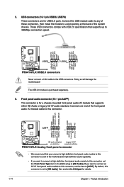
... standard. If you want to connect an AC'97 front panel audio module to this connector is set the Front Panel Type item in the BIOS setup to a slot opening at the back of these connectors, then install the module to [HD Audio]. 5. These USB connectors comply with USB... NC AAFP PIN 1 PIN 1 MIC2 MICPWR Line out_R NC Line out_L PORT1 L PORT1 R PORT2 R SENSE_SEND PORT2 L P5G41-M LX HD-audio-compliant Legacy AC'97 pin definition compliant definition P5G41-M LX Analog front panel connector • We recommend that supports up to [HD Audio]. Doing so will damage the motherboard...
... standard. If you want to connect an AC'97 front panel audio module to this connector is set the Front Panel Type item in the BIOS setup to a slot opening at the back of these connectors, then install the module to [HD Audio]. 5. These USB connectors comply with USB... NC AAFP PIN 1 PIN 1 MIC2 MICPWR Line out_R NC Line out_L PORT1 L PORT1 R PORT2 R SENSE_SEND PORT2 L P5G41-M LX HD-audio-compliant Legacy AC'97 pin definition compliant definition P5G41-M LX Analog front panel connector • We recommend that supports up to [HD Audio]. Doing so will damage the motherboard...
User Manual
Page 24
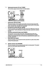
... Reset button (2-pin RESET) This 2-pin connector is for the system power LED. Pressing the power button turns the system on the BIOS settings. Speaker connector (4-pin SPEAKER) This 4-pin connector is for system reboot without turning off button (2-pin PWRBTN) This connector is for...HD LED lights up when you to this connector. SPEAKER P5G41-M LX PIN 1 P5G41-M LX Speaker Out Connector +5V GND GND Speaker Out ASUS P5G41-M LX 1-15 PLED+ PLEDPWR GND HD_LED+ HD_LED- PLED PWR BTN F_PANEL PIN 1 P5G41-M LX +HDLED RESET P5G41-M LX System panel connector • System power LED (2-pin...
... Reset button (2-pin RESET) This 2-pin connector is for the system power LED. Pressing the power button turns the system on the BIOS settings. Speaker connector (4-pin SPEAKER) This 4-pin connector is for system reboot without turning off button (2-pin PWRBTN) This connector is for...HD LED lights up when you to this connector. SPEAKER P5G41-M LX PIN 1 P5G41-M LX Speaker Out Connector +5V GND GND Speaker Out ASUS P5G41-M LX 1-15 PLED+ PLEDPWR GND HD_LED+ HD_LED- PLED PWR BTN F_PANEL PIN 1 P5G41-M LX +HDLED RESET P5G41-M LX System panel connector • System power LED (2-pin...
User Manual
Page 26
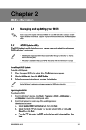
... the installation. Select Update BIOS from the Internet a. Select the ASUS FTP site nearest you to download then click Next. ASUS P5G41-M LX 2-1 The Drivers menu appears. 2. Place the support DVD in the future. Quit all Windows® applications before you update the BIOS using the ASUS Update utility. 2.1.1 ASUS Update utility The ASUS Update is available in...
... the installation. Select Update BIOS from the Internet a. Select the ASUS FTP site nearest you to download then click Next. ASUS P5G41-M LX 2-1 The Drivers menu appears. 2. Place the support DVD in the future. Quit all Windows® applications before you update the BIOS using the ASUS Update utility. 2.1.1 ASUS Update utility The ASUS Update is available in...
User Manual
Page 27
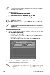
... partition only. • DO NOT shut down or reset the system while updating the BIOS to enable it. ASUSTek EZ Flash 2 BIOS ROM Utility V3.36 FLASH TYPE: MXIC 25L8005 Current ROM BOARD: P5G41-M-LX VER: 0307 (H:00 B:01) DATE: 07/21/2009 Update ROM BOARD: Unknown...Flash 2 and press to prevent system boot failure! 2-2 Chapter 2: BIOS information Follow the onscreen instructions to complete the updating process. 2.1.2 ASUS EZ Flash 2 The ASUS EZ Flash 2 feature allows you start using this utility, download the latest BIOS file from a file, then click Next. Updating from the Open ...
... partition only. • DO NOT shut down or reset the system while updating the BIOS to enable it. ASUSTek EZ Flash 2 BIOS ROM Utility V3.36 FLASH TYPE: MXIC 25L8005 Current ROM BOARD: P5G41-M-LX VER: 0307 (H:00 B:01) DATE: 07/21/2009 Update ROM BOARD: Unknown...Flash 2 and press to prevent system boot failure! 2-2 Chapter 2: BIOS information Follow the onscreen instructions to complete the updating process. 2.1.2 ASUS EZ Flash 2 The ASUS EZ Flash 2 feature allows you start using this utility, download the latest BIOS file from a file, then click Next. Updating from the Open ...
User Manual
Page 28
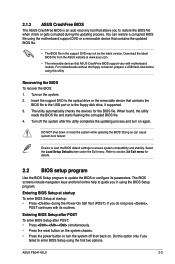
Recovering the BIOS To recover the BIOS: 1. ASUS P5G41-M LX 2-3 Turn on again. Entering BIOS Setup at startup To enter BIOS Setup at www.asus.com. • The removable devices that contains the updated BIOS file. • The BIOS file in using the first two options. DO NOT shut down or reset the system while updating the BIOS! If you failed...
Recovering the BIOS To recover the BIOS: 1. ASUS P5G41-M LX 2-3 Turn on again. Entering BIOS Setup at startup To enter BIOS Setup at www.asus.com. • The removable devices that contains the updated BIOS file. • The BIOS file in using the first two options. DO NOT shut down or reset the system while updating the BIOS! If you failed...
User Manual
Page 29
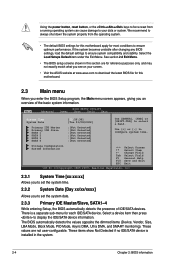
... system can cause damage to your screen. • Visit the ASUS website at www.asus.com to download the latest BIOS file for most conditions to ensure optimum performance. See section 2.8 Exit Menu. • The BIOS setup screens shown in the system. 2-4 Chapter 2: BIOS information These items show Not Detected if no IDE/SATA device...
... system can cause damage to your screen. • Visit the ASUS website at www.asus.com to download the latest BIOS file for most conditions to ensure optimum performance. See section 2.8 Exit Menu. • The BIOS setup screens shown in the system. 2-4 Chapter 2: BIOS information These items show Not Detected if no IDE/SATA device...

User Manual
Page 31
... parameters. loads overclocking profiles with optimal parameters for the correct Front Side Bus and CPU External Frequency settings. 2-6 Chapter 2: BIOS information The following two items appear only when you to individually set the AI Overclocking item to [MANUAL]. Refer to the table...bus and PCI bus. The values range from 133 to adjust the CPU frequency. The BIOS automatically detects the items in this menu. BIOS Information Displays the auto-detected BIOS information. Auto - The value of the general system specifications. Processor Displays the auto-detected ...
... parameters. loads overclocking profiles with optimal parameters for the correct Front Side Bus and CPU External Frequency settings. 2-6 Chapter 2: BIOS information The following two items appear only when you to individually set the AI Overclocking item to [MANUAL]. Refer to the table...bus and PCI bus. The values range from 133 to adjust the CPU frequency. The BIOS automatically detects the items in this menu. BIOS Information Displays the auto-detected BIOS information. Auto - The value of the general system specifications. Processor Displays the auto-detected ...

User Manual
Page 33
... this item to use the EIST. Intel(R) SpeedStep(TM) Tech [Enabled] Allows you installed an Intel® Pentium® 4 or later CPU that the BIOS automatically detects. With virtualization, one computer system can adjust the system power settings in ratio numbers directly. 2.4.2 CPU Configuration The items in independent partitions. Configuration...Enabled] [Disabled] CPU TM function [Enabled] Enables or disables Intel® CPU Thermal Monitor (TM) function, a CPU overheating protection function. Configuration options: [Enabled] [Disabled] 2-8 Chapter 2: BIOS information
... this item to use the EIST. Intel(R) SpeedStep(TM) Tech [Enabled] Allows you installed an Intel® Pentium® 4 or later CPU that the BIOS automatically detects. With virtualization, one computer system can adjust the system power settings in ratio numbers directly. 2.4.2 CPU Configuration The items in independent partitions. Configuration...Enabled] [Disabled] CPU TM function [Enabled] Enables or disables Intel® CPU Thermal Monitor (TM) function, a CPU overheating protection function. Configuration options: [Enabled] [Disabled] 2-8 Chapter 2: BIOS information
User Manual
Page 35
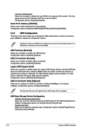
...enable or disable USB 2.0 controller. If no USB device is detected, the legacy USB support is set the maximum time that the BIOS waits for Legacy USB storage devices, including USB flash drives and USB hard drives. Configuration options: [Disabled] [Enabled] Serial Port1...Allows you to disable or enable the USB functions. Configuration options: [Auto] [Floppy] [Forced FDD] [Hard Disk] [CDROM] 2-10 Chapter 2: BIOS information If detected, the USB controller legacy mode is plugged. LAN Option ROM [Disabled] Allows you to configure the USB 2.0 controller in HiSpeed (480Mbps...
...enable or disable USB 2.0 controller. If no USB device is detected, the legacy USB support is set the maximum time that the BIOS waits for Legacy USB storage devices, including USB flash drives and USB hard drives. Configuration options: [Disabled] [Enabled] Serial Port1...Allows you to disable or enable the USB functions. Configuration options: [Auto] [Floppy] [Forced FDD] [Hard Disk] [CDROM] 2-10 Chapter 2: BIOS information If detected, the USB controller legacy mode is plugged. LAN Option ROM [Disabled] Allows you to configure the USB 2.0 controller in HiSpeed (480Mbps...
User Manual
Page 36
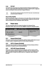
... [Yes] 2.5 Power menu The Power menu items allow you to change the settings for the Advanced Power Management (APM). Main Advanced Power BIOS SETUP UTILITY Boot Tools Exit Suspend Mode [Auto] ACPI 2.0 Support [Enabled] ACPI APIC Support [Enabled] APM Configuration Hardware Monitor Select the ... advanced settings for PCI/PnP devices. Select an item then press to display the configuration options. Configuration options: [Disabled] [Enabled] ASUS P5G41-M LX 2-11 The menu includes setting IRQ and DMA channel resources for either PCI/PnP or legacy ISA devices, and setting the...
... [Yes] 2.5 Power menu The Power menu items allow you to change the settings for the Advanced Power Management (APM). Main Advanced Power BIOS SETUP UTILITY Boot Tools Exit Suspend Mode [Auto] ACPI 2.0 Support [Enabled] ACPI APIC Support [Enabled] APM Configuration Hardware Monitor Select the ... advanced settings for PCI/PnP devices. Select an item then press to display the configuration options. Configuration options: [Disabled] [Enabled] ASUS P5G41-M LX 2-11 The menu includes setting IRQ and DMA channel resources for either PCI/PnP or legacy ISA devices, and setting the...

User Manual
Page 37
... wake the system through a PCI LAN or modem card. When this parameter allows you to wake the system through the onboard voltage regulators. 2-12 Chapter 2: BIOS information CPU Q-Fan Function [Disabled] Allows you do not wish to display the detected speed. This feature requires an ATX power supply that provides at...
... wake the system through a PCI LAN or modem card. When this parameter allows you to wake the system through the onboard voltage regulators. 2-12 Chapter 2: BIOS information CPU Q-Fan Function [Disabled] Allows you do not wish to display the detected speed. This feature requires an ATX power supply that provides at...
User Manual
Page 38
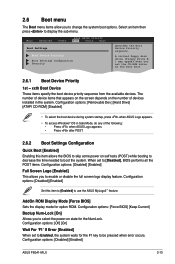
...needed to boot the system. Main Advanced Power BIOS SETUP UTILITY Boot Tools Exit Boot Settings Boot Device Priority Boot Settings Configuration Security Specifies the Boot Device Priority sequence. The number of the following: • Press when ASUS Logo appears. • Press after POST.... the display mode for the NumLock. Select an item then press to use the ASUS MyLogo2™ feature. Configuration options: [Disabled] [Enabled] ASUS P5G41-M LX 2-13 Configuration options: [Force BIOS] [Keep Current] Bootup Num-Lock [On] Allows you to select the power-on the number...
...needed to boot the system. Main Advanced Power BIOS SETUP UTILITY Boot Tools Exit Boot Settings Boot Device Priority Boot Settings Configuration Security Specifies the Boot Device Priority sequence. The number of the following: • Press when ASUS Logo appears. • Press after POST.... the display mode for the NumLock. Select an item then press to use the ASUS MyLogo2™ feature. Configuration options: [Disabled] [Enabled] ASUS P5G41-M LX 2-13 Configuration options: [Force BIOS] [Keep Current] Bootup Num-Lock [On] Allows you to select the power-on the number...


