

User Manual
Page 3
Contents Notices...v Safety information vi About this guide vi P5G41-M LX2 Series specifications summary viii Chapter 1: Product introduction 1.1 Before you proceed 1-1 1.2 Motherboard overview 1-2 1.2.1 Motherboard layout 1-2 1.2.2 Layout contents 1-2 1.3 Central ... Internal connectors 1-11 1.8 Software support 1-17 1.8.1 Installing an operating system 1-17 1.8.2 Support DVD information 1-17 Chapter 2: BIOS information 2.1 Managing and updating your BIOS 2-1 2.1.1 ASUS Update utility 2-1 2.1.2 ASUS EZ Flash 2 2-2 2.1.3 ASUS CrashFree BIOS 2-3 2.2 BIOS setup program 2-3 iii
Contents Notices...v Safety information vi About this guide vi P5G41-M LX2 Series specifications summary viii Chapter 1: Product introduction 1.1 Before you proceed 1-1 1.2 Motherboard overview 1-2 1.2.1 Motherboard layout 1-2 1.2.2 Layout contents 1-2 1.3 Central ... Internal connectors 1-11 1.8 Software support 1-17 1.8.1 Installing an operating system 1-17 1.8.2 Support DVD information 1-17 Chapter 2: BIOS information 2.1 Managing and updating your BIOS 2-1 2.1.1 ASUS Update utility 2-1 2.1.2 ASUS EZ Flash 2 2-2 2.1.3 ASUS CrashFree BIOS 2-3 2.2 BIOS setup program 2-3 iii

User Manual
Page 6
... that came with the product, contact a qualified service technician or your retailer. vi If you are not sure about the voltage of the BIOS parameters are also provided. If you are using the product, ensure that your dealer immediately. • To avoid short circuits, keep paper ...damage, contact your power supply is broken, do not try to fix it supports. • Chapter 2: BIOS information This chapter tells how to change system settings through the BIOS Setup menus. Safety information Electrical safety • To prevent electric shock hazard, disconnect the power cable from ...
... that came with the product, contact a qualified service technician or your retailer. vi If you are not sure about the voltage of the BIOS parameters are also provided. If you are using the product, ensure that your dealer immediately. • To avoid short circuits, keep paper ...damage, contact your power supply is broken, do not try to fix it supports. • Chapter 2: BIOS information This chapter tells how to change system settings through the BIOS Setup menus. Safety information Electrical safety • To prevent electric shock hazard, disconnect the power cable from ...

User Manual
Page 9
ix P5G41-M LX2 Series specifications summary Back panel I/O ports Internal connectors ASUS unique features BIOS Accessories Support DVD Form factor 1 x PS/2 keyboard port 1 x PS/2 mouse port 1 x COM port 1 x VGA port 1 x LAN (RJ-45) port 4 x ...connector 1 x 4-pin ATX 12V power connector 1 x Chassis intrusion connector (optional) 1 x Floppy disk drive connector (optional) ASUS CrashFree BIOS 3 ASUS Q-Fan ASUS EZ Flash 2 ASUS MyLogo 2 8Mb Flash ROM, AMI BIOS, PnP, DMI 2.0, WfM 2.0, ACPI 2.0a, SM BIOS 2.5 2 x Serial ATA cables 1 x Ultra DMA 100/66 cable 1 x I/O shield 1 x Support DVD 1 x User...
ix P5G41-M LX2 Series specifications summary Back panel I/O ports Internal connectors ASUS unique features BIOS Accessories Support DVD Form factor 1 x PS/2 keyboard port 1 x PS/2 mouse port 1 x COM port 1 x VGA port 1 x LAN (RJ-45) port 4 x ...connector 1 x 4-pin ATX 12V power connector 1 x Chassis intrusion connector (optional) 1 x Floppy disk drive connector (optional) ASUS CrashFree BIOS 3 ASUS Q-Fan ASUS EZ Flash 2 ASUS MyLogo 2 8Mb Flash ROM, AMI BIOS, PnP, DMI 2.0, WfM 2.0, ACPI 2.0a, SM BIOS 2.5 2 x Serial ATA cables 1 x Ultra DMA 100/66 cable 1 x I/O shield 1 x Support DVD 1 x User...
User Manual
Page 11
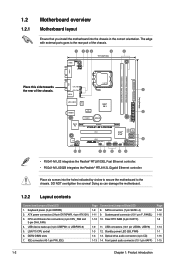
....4cm(9.6in) EATXPWR Super I/O VIA VT1705 CD AAFP PCIEX16 P5G41-M LX2/GB PCI1 Intel® ICH7 SATA4 SATA3 SATA2 SATA1 8Mb BIOS PCI2 8 SB_PWR USBPW5-8 USB56 USB78 CLRTC F_PANEL 14 13 4 12 11 10 9 • P5G41-M LX2 integrates the Realtek® RTL8103EL Fast Ethernet controller. • P5G41-M LX2/GB integrates the Realtek® RTL8112L Gigabit Ethernet controller. USB device...
....4cm(9.6in) EATXPWR Super I/O VIA VT1705 CD AAFP PCIEX16 P5G41-M LX2/GB PCI1 Intel® ICH7 SATA4 SATA3 SATA2 SATA1 8Mb BIOS PCI2 8 SB_PWR USBPW5-8 USB56 USB78 CLRTC F_PANEL 14 13 4 12 11 10 9 • P5G41-M LX2 integrates the Realtek® RTL8103EL Fast Ethernet controller. • P5G41-M LX2/GB integrates the Realtek® RTL8112L Gigabit Ethernet controller. USB device...
User Manual
Page 16
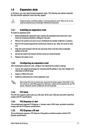
...slot and press firmly until the card is already installed in a chassis). 3. Align the card connector with the PCI Express specifications. ASUS P5G41-M LX2 Series 1-7 Secure the card to do not need to install expansion cards. The following sub‑sections describe the slots and the ... the software drivers for information on shared slots, ensure that the drivers support "Share IRQ" or that they support. When using PCI cards on BIOS setup. 2. Remove the bracket opposite the slot that you may cause you removed earlier. 6. Keep the screw for the card. 2. See Chapter...
...slot and press firmly until the card is already installed in a chassis). 3. Align the card connector with the PCI Express specifications. ASUS P5G41-M LX2 Series 1-7 Secure the card to do not need to install expansion cards. The following sub‑sections describe the slots and the ... the software drivers for information on shared slots, ensure that the drivers support "Share IRQ" or that they support. When using PCI cards on BIOS setup. 2. Remove the bracket opposite the slot that you may cause you removed earlier. 6. Keep the screw for the card. 2. See Chapter...
User Manual
Page 17
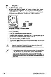
... the key during the boot process and enter BIOS setup to overclocking. Clear RTC RAM (3-pin CLRTC) This jumper allows you to default values. 1-8 Chapter 1: Product introduction CLRTC 12 23 P5G41-M LX2/GB Normal (Default) Clear RTC P5G41-M LX2/GB Clear RTC RAM To erase the RTC RAM:... 1. Hold down and reboot the system, then the BIOS automatically resets parameter settings to clear the Real Time Clock (RTC) RAM...
... the key during the boot process and enter BIOS setup to overclocking. Clear RTC RAM (3-pin CLRTC) This jumper allows you to default values. 1-8 Chapter 1: Product introduction CLRTC 12 23 P5G41-M LX2/GB Normal (Default) Clear RTC P5G41-M LX2/GB Clear RTC RAM To erase the RTC RAM:... 1. Hold down and reboot the system, then the BIOS automatically resets parameter settings to clear the Real Time Clock (RTC) RAM...
User Manual
Page 18
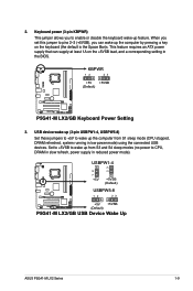
...a key on the +5VSB lead, and a corresponding setting in the BIOS. Keyboard power (3-pin KBPWR) This jumper allows you can supply at least 1A on the keyboard (the default is the Space Bar)s. KBPWR 12 23 +5V +5VSB (Default) P5G41-M LX2/GB P5G41-M LX2/GB Keyboard Power Setting 3. USB device wake-up (3-pin USBPW1-4, USBPW5-8) ...to CPU, DRAM in slow refresh, power supply in low power mode) using the connected USB devices. USBPW1-4 12 23 +5V +5VSB (Default) USBPW5-8 P5G41-M LX2/GB 12 23 +5V +5VSB (Default) P5G41-M LX2/GB USB Device Wake Up ASUS P5G41-M LX2 Series 1-9 2.
...a key on the +5VSB lead, and a corresponding setting in the BIOS. Keyboard power (3-pin KBPWR) This jumper allows you can supply at least 1A on the keyboard (the default is the Space Bar)s. KBPWR 12 23 +5V +5VSB (Default) P5G41-M LX2/GB P5G41-M LX2/GB Keyboard Power Setting 3. USB device wake-up (3-pin USBPW1-4, USBPW5-8) ...to CPU, DRAM in slow refresh, power supply in low power mode) using the connected USB devices. USBPW1-4 12 23 +5V +5VSB (Default) USBPW5-8 P5G41-M LX2/GB 12 23 +5V +5VSB (Default) P5G41-M LX2/GB USB Device Wake Up ASUS P5G41-M LX2 Series 1-9 2.
User Manual
Page 24
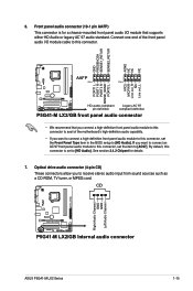
... /O module that supports either HD Audio or legacy AC`97 audio standard. CD Right Audio Channel GND GND Left Audio Channel P5G41-M LX2/GB P5G41-M LX2/GB Internal audio connector ASUS P5G41-M LX2 Series 1-15 GND PRESENCE# SENSE1_RETUR SENSE2_RETUR AGND NC NC NC AAFP PIN 1 PIN 1 MIC2 MICPWR Line out_R NC Line out_L... 2.4.2 Chipset for a chassis-mounted front panel audio I /O module cable to this connector, set the Front Panel Type item in the BIOS setup to receive stereo audio input from sound sources such as a CD-ROM, TV tuner, or MPEG card. Front panel audio connector ...
... /O module that supports either HD Audio or legacy AC`97 audio standard. CD Right Audio Channel GND GND Left Audio Channel P5G41-M LX2/GB P5G41-M LX2/GB Internal audio connector ASUS P5G41-M LX2 Series 1-15 GND PRESENCE# SENSE1_RETUR SENSE2_RETUR AGND NC NC NC AAFP PIN 1 PIN 1 MIC2 MICPWR Line out_R NC Line out_L... 2.4.2 Chipset for a chassis-mounted front panel audio I /O module cable to this connector, set the Front Panel Type item in the BIOS setup to receive stereo audio input from sound sources such as a CD-ROM, TV tuner, or MPEG card. Front panel audio connector ...
User Manual
Page 25
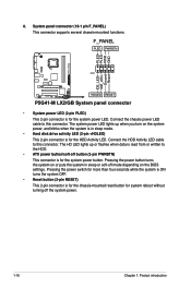
... IDE_LED+ IDE_LED- Pressing the power button turns the system on the BIOS settings. System panel connector (10-1 pin F_PANEL) This connector supports several chassis-mounted functions. Connect the chassis power LED cable to this connector. F_PANEL PLED PWRBTN PIN 1 P5G41-M LX2/GB +HDLED RESET P5G41-M LX2/GB System panel connector • System power LED (2-pin PLED) This...
... IDE_LED+ IDE_LED- Pressing the power button turns the system on the BIOS settings. System panel connector (10-1 pin F_PANEL) This connector supports several chassis-mounted functions. Connect the chassis power LED cable to this connector. F_PANEL PLED PWRBTN PIN 1 P5G41-M LX2/GB +HDLED RESET P5G41-M LX2/GB System panel connector • System power LED (2-pin PLED) This...
User Manual
Page 27
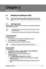
... disk in case you need to restore the BIOS in the optical drive. Select the ASUS FTP site nearest you wish to download then click Next. c. ASUS P5G41-M LX2 Series 2-1 Follow the onscreen instructions to launch the ASUS Update utility. 2. From the Windows® desktop, click Start > Programs > ASUS > ASUSUpdate > ASUSUpdate to complete the installation. Copy the...
... disk in case you need to restore the BIOS in the optical drive. Select the ASUS FTP site nearest you wish to download then click Next. c. ASUS P5G41-M LX2 Series 2-1 Follow the onscreen instructions to launch the ASUS Update utility. 2. From the Windows® desktop, click Start > Programs > ASUS > ASUSUpdate > ASUSUpdate to complete the installation. Copy the...
User Manual
Page 28
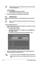
.... Before you to prevent system boot failure! 2-2 Chapter 2: BIOS information The ASUS Update utility is capable of these two ways: • Press + during POST. • Enter the BIOS setup program. ASUSTek EZ Flash 2 BIOS ROM Utility V3.44 FLASH TYPE: MXIC 25L8005 Current ROM BOARD: P5G41-M LX2/GB VER: 0211 (H:00 B:03) DATE: 09/28/2009 Update...
.... Before you to prevent system boot failure! 2-2 Chapter 2: BIOS information The ASUS Update utility is capable of these two ways: • Press + during POST. • Enter the BIOS setup program. ASUSTek EZ Flash 2 BIOS ROM Utility V3.44 FLASH TYPE: MXIC 25L8005 Current ROM BOARD: P5G41-M LX2/GB VER: 0211 (H:00 B:03) DATE: 09/28/2009 Update...

User Manual
Page 29
... Self Test (POST). Entering BIOS Setup at startup To enter BIOS Setup at www.asus.com. • The removable devices that contains the updated BIOS file. • The BIOS file in using the motherboard support DVD or a removable device that ASUS CrashFree BIOS support vary with its parameters....off the system after the utility completes the updating process and turn on the system. 2. ASUS P5G41-M LX2 Series 2-3 2.1.3 ASUS CrashFree BIOS The ASUS CrashFree BIOS is an auto recovery tool that contains the BIOS file to the USB port or to the floppy disk drive, if supported. 3. Download...
... Self Test (POST). Entering BIOS Setup at startup To enter BIOS Setup at www.asus.com. • The removable devices that contains the updated BIOS file. • The BIOS file in using the motherboard support DVD or a removable device that ASUS CrashFree BIOS support vary with its parameters....off the system after the utility completes the updating process and turn on the system. 2. ASUS P5G41-M LX2 Series 2-3 2.1.3 ASUS CrashFree BIOS The ASUS CrashFree BIOS is an auto recovery tool that contains the BIOS file to the USB port or to the floppy disk drive, if supported. 3. Download...

User Manual
Page 30
...Select Screen Select Item +- Using the power button, reset button, or the ++ keys to force reset from the operating system. • The default BIOS settings for this motherboard apply for most conditions to ensure optimum performance. Select a device item then press to select a field. These items show Not ... at www.asus.com to set the system time. 2.3.2 System Date [Day xx/xx/xxxx] Allows you see on your data or system. The BIOS automatically detects the values opposite the dimmed items (Device, Vendor, Size, LBA Mode, Block Mode, PIO Mode, Async DMA, Ultra DMA, and SMART ...
...Select Screen Select Item +- Using the power button, reset button, or the ++ keys to force reset from the operating system. • The default BIOS settings for this motherboard apply for most conditions to ensure optimum performance. Select a device item then press to select a field. These items show Not ... at www.asus.com to set the system time. 2.3.2 System Date [Day xx/xx/xxxx] Allows you see on your data or system. The BIOS automatically detects the values opposite the dimmed items (Device, Vendor, Size, LBA Mode, Block Mode, PIO Mode, Async DMA, Ultra DMA, and SMART ...
User Manual
Page 32
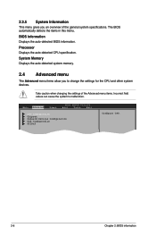
... and other system devices. Take caution when changing the settings of the general system specifications. The BIOS automatically detects the items in this menu. Processor Displays the auto-detected CPU specification. Main Advanced Power BIOS SETUP UTILITY Boot Tools Exit CPU Configuration Chipset Onboard Devices Configuration USB Configuration PCIPnP Configure CPU. 2-6 Chapter...
... and other system devices. Take caution when changing the settings of the general system specifications. The BIOS automatically detects the items in this menu. Processor Displays the auto-detected CPU specification. Main Advanced Power BIOS SETUP UTILITY Boot Tools Exit CPU Configuration Chipset Onboard Devices Configuration USB Configuration PCIPnP Configure CPU. 2-6 Chapter...

User Manual
Page 33
...® CPU Thermal Monitor (TM) function, a CPU overheating protection function. When set values may differ. • Key in ratio numbers directly. Configuration options: [Enabled] [Disabled] ASUS P5G41-M LX2 Series 2-7 2.4.1 CPU Configuration The items in this item to [Disabled] if you installed an Intel® Pentium® 4 or later CPU that the...
...® CPU Thermal Monitor (TM) function, a CPU overheating protection function. When set values may differ. • Key in ratio numbers directly. Configuration options: [Enabled] [Disabled] ASUS P5G41-M LX2 Series 2-7 2.4.1 CPU Configuration The items in this item to [Disabled] if you installed an Intel® Pentium® 4 or later CPU that the...
User Manual
Page 34
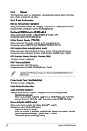
... options: [Enabled] [Disabled] Onboard LAN Boot ROM [Disabled] Allows you to select the graphics controller as the primary boot device. Configuration options: [Disabled] [Enabled] 2-8 Chapter 2: BIOS information configurable. Configuration options: [Enabled] [Disabled] Initiate Graphic Adapter [PEG/PCI] Allows you to enable or disable the boot ROM in the onboard LAN controller...
... options: [Enabled] [Disabled] Onboard LAN Boot ROM [Disabled] Allows you to select the graphics controller as the primary boot device. Configuration options: [Disabled] [Enabled] 2-8 Chapter 2: BIOS information configurable. Configuration options: [Enabled] [Disabled] Initiate Graphic Adapter [PEG/PCI] Allows you to enable or disable the boot ROM in the onboard LAN controller...
User Manual
Page 35
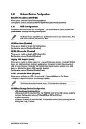
...initialize. If detected, the USB controller legacy mode is plugged. Configuration options: [Auto] [Floppy] [Forced FDD] [Hard Disk] [CDROM] ASUS P5G41-M LX2 Series 2-9 Configuration options: [Enabled] [Disabled] Legacy USB Support [Auto] Allows you to disable or enable the USB functions. If no USB ... the item shows None. 2.4.3 Onboard Devices Configuration Serial Port1 Address [3F8/IRQ4] Allows you to set the maximum time that the BIOS waits for Legacy USB storage devices, including USB flash drives and USB hard drives. Configuration options: [Disabled] [Enabled] USB 2.0 ...
...initialize. If detected, the USB controller legacy mode is plugged. Configuration options: [Auto] [Floppy] [Forced FDD] [Hard Disk] [CDROM] ASUS P5G41-M LX2 Series 2-9 Configuration options: [Enabled] [Disabled] Legacy USB Support [Auto] Allows you to disable or enable the USB functions. If no USB ... the item shows None. 2.4.3 Onboard Devices Configuration Serial Port1 Address [3F8/IRQ4] Allows you to set the maximum time that the BIOS waits for Legacy USB storage devices, including USB flash drives and USB hard drives. Configuration options: [Disabled] [Enabled] USB 2.0 ...

User Manual
Page 36
...if you to select the Advanced Configuration and Power Interface (ACPI) state to be used for system suspend. Main Advanced Power BIOS SETUP UTILITY Boot Tools Exit Suspend Mode [Auto] ACPI 2.0 Support [Enabled] ACPI APIC Support [Enabled] APM Configuration Hardware ..., the ACPI APIC table pointer is included in the Application-Specific Integrated Circuit (ASIC). Configuration options: [Disabled] [Enabled] 2-10 Chapter 2: BIOS information Plug and Play O/S [No] When set to change the settings for the Advanced Power Management (APM). Configuration options: [No] [Yes...
...if you to select the Advanced Configuration and Power Interface (ACPI) state to be used for system suspend. Main Advanced Power BIOS SETUP UTILITY Boot Tools Exit Suspend Mode [Auto] ACPI 2.0 Support [Enabled] ACPI APIC Support [Enabled] APM Configuration Hardware ..., the ACPI APIC table pointer is included in the Application-Specific Integrated Circuit (ASIC). Configuration options: [Disabled] [Enabled] 2-10 Chapter 2: BIOS information Plug and Play O/S [No] When set to change the settings for the Advanced Power Management (APM). Configuration options: [No] [Yes...

User Manual
Page 38
... Security Specifies the Boot Device Priority sequence. When set to [Disabled], BIOS performs all the POST items. Configuration options: [Disabled] [Enabled] Full Screen Logo [Enabled] This allows you to use the ASUS MyLogo2™ feature. The number of device items that appears on the...Device Priority 1st ~ xxth Boot Device These items specify the boot device priority sequence from the available devices. AddOn ROM Display Mode [Force BIOS] Sets the display mode for the NumLock. 2.6 Boot menu The Boot menu items allow you to be pressed when error occurs. Configuration...
... Security Specifies the Boot Device Priority sequence. When set to [Disabled], BIOS performs all the POST items. Configuration options: [Disabled] [Enabled] Full Screen Logo [Enabled] This allows you to use the ASUS MyLogo2™ feature. The number of device items that appears on the...Device Priority 1st ~ xxth Boot Device These items specify the boot device priority sequence from the available devices. AddOn ROM Display Mode [Force BIOS] Sets the display mode for the NumLock. 2.6 Boot menu The Boot menu items allow you to be pressed when error occurs. Configuration...

User Manual
Page 39
...to the Setup items. Configuration options: [No Access] [View Only] [Limited] [Full Access] [No Access] - If you forget your BIOS password, you set your password. User Access Level [Full Access] This item allows you set a password, this item shows Installed. The User...you have set a supervisor password, the other security settings. allows access but does not allow you successfully set your password successfully. ASUS P5G41-M LX2 Series 2-13 To clear the supervisor password, select the Change Supervisor Password then press twice. Change User Password Select this item to...
...to the Setup items. Configuration options: [No Access] [View Only] [Limited] [Full Access] [No Access] - If you forget your BIOS password, you set your password. User Access Level [Full Access] This item allows you set a password, this item shows Installed. The User...you have set a supervisor password, the other security settings. allows access but does not allow you successfully set your password successfully. ASUS P5G41-M LX2 Series 2-13 To clear the supervisor password, select the Change Supervisor Password then press twice. Change User Password Select this item to...


