User Manual
Page 5
This equipment has been tested and found to comply with FCC regulations. The use of shielded cables for connection of the monitor to the graphics card is subject to the following measures: • Reorient or relocate the receiving antenna. • ...with the REACH (Registration, Evaluation, Authorisation, and Restriction of Chemicals) regulatory framework, we published the chemical substances in our products at ASUS REACH website at http://green.asus.com/english/REACH.htm. This symbol of the crossed out wheeled bin indicates that interference will not occur in accordance with Part 15...
This equipment has been tested and found to comply with FCC regulations. The use of shielded cables for connection of the monitor to the graphics card is subject to the following measures: • Reorient or relocate the receiving antenna. • ...with the REACH (Registration, Evaluation, Authorisation, and Restriction of Chemicals) regulatory framework, we published the chemical substances in our products at ASUS REACH website at http://green.asus.com/english/REACH.htm. This symbol of the crossed out wheeled bin indicates that interference will not occur in accordance with Part 15...
User Manual
Page 6
... Setup menus. Detailed descriptions of the electrical outlet you add a device. • Before connecting or removing signal cables from the existing system before the signal cables are connected. Contact a qualified service technician or your area. Operation safety • Before installing the motherboard and ... stable surface. • If you encounter technical problems with the package. • Before using the product, ensure that all power cables are also provided. How this guide This user guide contains the information you detect any area where it may become wet. •...
... Setup menus. Detailed descriptions of the electrical outlet you add a device. • Before connecting or removing signal cables from the existing system before the signal cables are connected. Contact a qualified service technician or your area. Operation safety • Before installing the motherboard and ... stable surface. • If you encounter technical problems with the package. • Before using the product, ensure that all power cables are also provided. How this guide This user guide contains the information you detect any area where it may become wet. •...
User Manual
Page 9
... ASUS unique features BIOS Manageability Support DVD Accessories Form factor 1 x PS/2 keyboard port 1 x PS/2 mouse port 1 x COM port 1 x VGA port 1 x LAN (RJ-45) port 4 x USB 2.0/1.1 ports 1 x LPT port (optional for P5G41T-M LX2 and P5G41T-M LX2/GB)...LX2/GB) 1 x Floppy disk drive connector (optional for P5G41T-M LX2 and P5G41T-M LX2/GB) ASUS CrashFree BIOS 3 ASUS Q-Fan ASUS EZ Flash 2 ASUS MyLogo 2 8Mb Flash ROM, AMI BIOS, PnP, DMI 2.0, WfM 2.0, ACPI 2.0a, SM BIOS 2.5 WOL, PXE, PME Wake up, WOR by Ring Drivers ASUS PC Probe II ASUS Update Anti-Virus software (OEM version) 2 x Serial ATA cables...
... ASUS unique features BIOS Manageability Support DVD Accessories Form factor 1 x PS/2 keyboard port 1 x PS/2 mouse port 1 x COM port 1 x VGA port 1 x LAN (RJ-45) port 4 x USB 2.0/1.1 ports 1 x LPT port (optional for P5G41T-M LX2 and P5G41T-M LX2/GB)...LX2/GB) 1 x Floppy disk drive connector (optional for P5G41T-M LX2 and P5G41T-M LX2/GB) ASUS CrashFree BIOS 3 ASUS Q-Fan ASUS EZ Flash 2 ASUS MyLogo 2 8Mb Flash ROM, AMI BIOS, PnP, DMI 2.0, WfM 2.0, ACPI 2.0a, SM BIOS 2.5 WOL, PXE, PME Wake up, WOR by Ring Drivers ASUS PC Probe II ASUS Update Anti-Virus software (OEM version) 2 x Serial ATA cables...
User Manual
Page 10
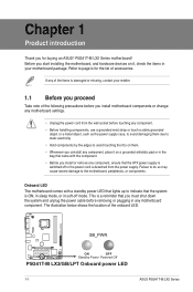
..., or in your retailer. 1.1 Before you uninstall any motherboard component. SB_PWR P5G41T-M LX2/GB/LPT ON OFF Standby Power Powered Off P5G41T-M LX2/GB/LPT Onboard power LED 1-1 ASUS P5G41T-M LX2 Series This is a reminder that you must shut down the system and unplug the power cable before touching any component. • Before handling components, use a grounded wrist strap...
..., or in your retailer. 1.1 Before you uninstall any motherboard component. SB_PWR P5G41T-M LX2/GB/LPT ON OFF Standby Power Powered Off P5G41T-M LX2/GB/LPT Onboard power LED 1-1 ASUS P5G41T-M LX2 Series This is a reminder that you must shut down the system and unplug the power cable before touching any component. • Before handling components, use a grounded wrist strap...
User Manual
Page 20
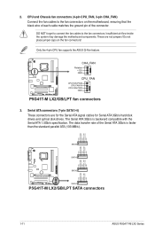
... RSATA_TXP2 GND GND RSATA_RXN1 RSATA_RXP1 GND RSATA_TXN1 RSATA_TXP1 GND P5G41T-M LX2/GB/LPT SATA2 SATA1 P5G41T-M LX2/GB/LPT SATA connectors 1-11 ASUS P5G41T-M LX2 Series 2. Insufficient air flow inside the system may damage the motherboard components. P5G41T-M LX2/GB/LPT CHA_FAN Rotation +12V GND CPU_FAN CPU FAN PWM CPU FAN... IN CPU FAN PWR GND P5G41T-M LX2/GB/LPT fan connectors 3. Only the 4-pin CPU fan supports the ASUS Q-Fan feature. These are for the Serial ATA signal cables for Serial ATA 3Gb/s hard disk drives and optical disk drives. ...
... RSATA_TXP2 GND GND RSATA_RXN1 RSATA_RXP1 GND RSATA_TXN1 RSATA_TXP1 GND P5G41T-M LX2/GB/LPT SATA2 SATA1 P5G41T-M LX2/GB/LPT SATA connectors 1-11 ASUS P5G41T-M LX2 Series 2. Insufficient air flow inside the system may damage the motherboard components. P5G41T-M LX2/GB/LPT CHA_FAN Rotation +12V GND CPU_FAN CPU FAN PWM CPU FAN... IN CPU FAN PWR GND P5G41T-M LX2/GB/LPT fan connectors 3. Only the 4-pin CPU fan supports the ASUS Q-Fan feature. These are for the Serial ATA signal cables for Serial ATA 3Gb/s hard disk drives and optical disk drives. ...
User Manual
Page 21
... Connect the blue connector to the motherboard's IDE connector, then select one of device(s) - P5G41T-M LX2/GB/LPT IDE connector Single device Two devices Drive jumper setting Cable-Select or Master Cable-Select Master Slave Mode of the following modes to match the covered hole on the IDE connector is removed... or gray • Pin 20 on the Ultra DMA cable connector. If any device jumper is for Ultra DMA 100/66 IDE devices. PIN1 PRI_IDE P5G41T-M LX2/GB/LPT NOTE:Orient the red markings on each Ultra DMA 100/66 signal cable: blue, black, and gray. Optical drive audio connector ...
... Connect the blue connector to the motherboard's IDE connector, then select one of device(s) - P5G41T-M LX2/GB/LPT IDE connector Single device Two devices Drive jumper setting Cable-Select or Master Cable-Select Master Slave Mode of the following modes to match the covered hole on the IDE connector is removed... or gray • Pin 20 on the Ultra DMA cable connector. If any device jumper is for Ultra DMA 100/66 IDE devices. PIN1 PRI_IDE P5G41T-M LX2/GB/LPT NOTE:Orient the red markings on each Ultra DMA 100/66 signal cable: blue, black, and gray. Optical drive audio connector ...
User Manual
Page 22
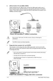
...USB_P8USB_P8+ GND NC USB+5V USB_P6USB_P6+ GND NC P5G41T-M LX2/GB/LPT USB56 PIN 1 USB78 PIN 1 USB+5V USB_P7USB_P7+ GND USB+5V USB_P5USB_P5+ GND P5G41T-M LX2/GB/LPT USB2.0 connectors Never connect a 1394 cable to PIN 1. USB connectors (10-1 pin USB56, USB78...) These connectors are for the floppy disk drive (FDD) signal cable. 6. Connect the USB module cable to any of these connectors, then install the module to a slot opening at the back of the system chassis. P5G41T-M LX2/GB/LPT Floppy disk drive connector 1-13 ASUS P5G41T-M LX2...
...USB_P8USB_P8+ GND NC USB+5V USB_P6USB_P6+ GND NC P5G41T-M LX2/GB/LPT USB56 PIN 1 USB78 PIN 1 USB+5V USB_P7USB_P7+ GND USB+5V USB_P5USB_P5+ GND P5G41T-M LX2/GB/LPT USB2.0 connectors Never connect a 1394 cable to PIN 1. USB connectors (10-1 pin USB56, USB78...) These connectors are for the floppy disk drive (FDD) signal cable. 6. Connect the USB module cable to any of these connectors, then install the module to a slot opening at the back of the system chassis. P5G41T-M LX2/GB/LPT Floppy disk drive connector 1-13 ASUS P5G41T-M LX2...
User Manual
Page 23
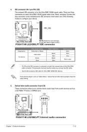
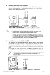
...connector (4-1 pin CHASSIS) This connector is for P5G41T-M LX2 and P5G41T-M LX2/GB. By default, the pins labeled "Chassis Signal" and "GND" are shorted with a jumper cap. CHASSIS +5VSB_MB Chassis Signal GND P5G41T-M LX2/GB/LPT P5G41T-M LX2/GB/LPT Chassis intrusion connector Chapter 1: Product introduction 1-14 8. ...that you connect a high-definition front panel audio module to this connector to avail of the chassis intrusion sensor or switch cable to this connector. See section 2.4.2 Chipset for a chassis-mounted intrusion detection sensor or switch. Remove the jumper caps ...
...connector (4-1 pin CHASSIS) This connector is for P5G41T-M LX2 and P5G41T-M LX2/GB. By default, the pins labeled "Chassis Signal" and "GND" are shorted with a jumper cap. CHASSIS +5VSB_MB Chassis Signal GND P5G41T-M LX2/GB/LPT P5G41T-M LX2/GB/LPT Chassis intrusion connector Chapter 1: Product introduction 1-14 8. ...that you connect a high-definition front panel audio module to this connector to avail of the chassis intrusion sensor or switch cable to this connector. See section 2.4.2 Chipset for a chassis-mounted intrusion detection sensor or switch. Remove the jumper caps ...
User Manual
Page 24
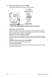
PLED+ PLEDPWR GND IDE_LED+ IDE_LED- Connect the HDD Activity LED cable to this connector. F_PANEL PWR LED PWR BTN PIN 1 P5G41T-M LX2/GB/LPT HD LED RESET P5G41T-M LX2/GB/LPT System panel connector • System power LED (2-pin PLED) This 2-pin connector is for the chassis-mounted reset...RESET) This 2-pin connector is for the HDD Activity LED. Connect the chassis power LED cable to the HDD. • ATX power button/soft-off the system power. 1-15 ASUS P5G41T-M LX2 Series System panel connector (10-1 pin F_PANEL) This connector supports several chassis-mounted functions. ...
PLED+ PLEDPWR GND IDE_LED+ IDE_LED- Connect the HDD Activity LED cable to this connector. F_PANEL PWR LED PWR BTN PIN 1 P5G41T-M LX2/GB/LPT HD LED RESET P5G41T-M LX2/GB/LPT System panel connector • System power LED (2-pin PLED) This 2-pin connector is for the chassis-mounted reset...RESET) This 2-pin connector is for the HDD Activity LED. Connect the chassis power LED cable to the HDD. • ATX power button/soft-off the system power. 1-15 ASUS P5G41T-M LX2 Series System panel connector (10-1 pin F_PANEL) This connector supports several chassis-mounted functions. ...


