User Guide
Page 15
... Documentation 2-in-1 disk drive cable (IDE and floppy disk drive cable) 4 x Serial ATA signal cables 4 x Serial ATA power cables I/O shield ASUS motherboard support CD User guide If any of ASUS quality motherboards! ASUS P5CR-VM 1-1 Thank you start installing the motherboard, and hardware devices on it another standout in your package with the list below... technologies, making it , check the items in the long line of the above items is damaged or missing, contact your motherboard package for buying an ASUS® P5CR-VM motherboard! 1.1 Welcome!
... Documentation 2-in-1 disk drive cable (IDE and floppy disk drive cable) 4 x Serial ATA signal cables 4 x Serial ATA power cables I/O shield ASUS motherboard support CD User guide If any of ASUS quality motherboards! ASUS P5CR-VM 1-1 Thank you start installing the motherboard, and hardware devices on it another standout in your package with the list below... technologies, making it , check the items in the long line of the above items is damaged or missing, contact your motherboard package for buying an ASUS® P5CR-VM motherboard! 1.1 Welcome!

User Guide
Page 17
... prevent overheating and damage. See pages 2-23 and 2-28 for timely failure detection. The system fan rotations per minute (RPM) is software compatible with USB 1.1. ASUS P5CR-VM 1-3 The ASIC monitors the voltage levels to provide a total solution for details. See page 2-17 for your networking needs. PCI Express features point-to Gigabit...
... prevent overheating and damage. See pages 2-23 and 2-28 for timely failure detection. The system fan rotations per minute (RPM) is software compatible with USB 1.1. ASUS P5CR-VM 1-3 The ASIC monitors the voltage levels to provide a total solution for details. See page 2-17 for your networking needs. PCI Express features point-to Gigabit...
User Guide
Page 20
Chapter summary 2 2.1 Before you proceed 2-1 2.2 Motherboard overview 2-2 2.3 Central Processing Unit (CPU 2-6 2.4 System memory 2-13 2.5 Expansion slots 2-15 2.6 Jumpers 2-18 2.7 Connectors 2-23 ASUS P5CR-VM
Chapter summary 2 2.1 Before you proceed 2-1 2.2 Motherboard overview 2-2 2.3 Central Processing Unit (CPU 2-6 2.4 System memory 2-13 2.5 Expansion slots 2-15 2.6 Jumpers 2-18 2.7 Connectors 2-23 ASUS P5CR-VM
User Guide
Page 21
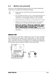
... pad or in soft-off or the power c o r d i s d e t a c h e d f r o m t h e p o w e r s u p p l y . The green LED lights up to the motherboard, peripherals, and/or components. P5CR-VM P5CR-VM Onboard LED SB_PWR1 ON Standby Power OFF Powered Off ASUS P5CR-VM 2-1 Failure to do so may cause severe damage to indicate that came with a standby power LED. Onboard LED The motherboard comes...
... pad or in soft-off or the power c o r d i s d e t a c h e d f r o m t h e p o w e r s u p p l y . The green LED lights up to the motherboard, peripherals, and/or components. P5CR-VM P5CR-VM Onboard LED SB_PWR1 ON Standby Power OFF Powered Off ASUS P5CR-VM 2-1 Failure to do so may cause severe damage to indicate that came with a standby power LED. Onboard LED The motherboard comes...

User Guide
Page 23
... CMOS Power CLRTC1 PCIE1 Intel ® ICH6R RECOVERY1 FRNT_FAN1 Broadcom BCM5721 REAR_FAN1 LAN_EN2 Super I/O REAR_FAN2 PCI1 PCI2 COM2 BPSMB1 USBPW56 USBPW78 USBPW34 8Mbit Flash BIOS P5CR-VM TRPWR1 FRNT_FAN2 BMCSOCKET1 FLOPPY1 USB34 USB56 USB78 HDLED1 BMCCONN1 PANEL1 AUX_PANEL1 SB_PWR1 SATA1 SATA2 SATA3 SATA4 ASUS P5CR-VM 2-3
... CMOS Power CLRTC1 PCIE1 Intel ® ICH6R RECOVERY1 FRNT_FAN1 Broadcom BCM5721 REAR_FAN1 LAN_EN2 Super I/O REAR_FAN2 PCI1 PCI2 COM2 BPSMB1 USBPW56 USBPW78 USBPW34 8Mbit Flash BIOS P5CR-VM TRPWR1 FRNT_FAN2 BMCSOCKET1 FLOPPY1 USB34 USB56 USB78 HDLED1 BMCCONN1 PANEL1 AUX_PANEL1 SB_PWR1 SATA1 SATA2 SATA3 SATA4 ASUS P5CR-VM 2-3
User Guide
Page 25
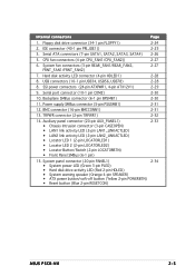
... HDLED) • System warning speaker (Orange 4-pin SPEAKER) • ATX power button/soft-off button (Yellow 2-pin POWERBTN) • Reset button (Blue 2-pin RESETCON) 2-34 ASUS P5CR-VM 2-5 Internal connectors Page 1. Floppy disk drive connector (34-1 pin FLOPPY1) 2-24 2. Hard disk activity LED connector (4-pin HDLED1) 2-28 8. Backplane SMBus connector (6-1 pin BPSMB1) 2-30...
... HDLED) • System warning speaker (Orange 4-pin SPEAKER) • ATX power button/soft-off button (Yellow 2-pin POWERBTN) • Reset button (Blue 2-pin RESETCON) 2-34 ASUS P5CR-VM 2-5 Internal connectors Page 1. Floppy disk drive connector (34-1 pin FLOPPY1) 2-24 2. Hard disk activity LED connector (4-pin HDLED1) 2-28 8. Backplane SMBus connector (6-1 pin BPSMB1) 2-30...
User Guide
Page 27
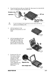
Gold triangle mark ASUS P5CR-VM A 2-7 Retention tab A Load lever PnP cap B This side of the socket box should fit into the CPU notch. Load plate 5. Position the CPU over the ...
Gold triangle mark ASUS P5CR-VM A 2-7 Retention tab A Load lever PnP cap B This side of the socket box should fit into the CPU notch. Load plate 5. Position the CPU over the ...

User Guide
Page 29
...) for the updated list of the groove pointing outward. (The photo shows the groove shaded for emphasis.) ASUS P5CR-VM 2-9 Orient the heatsink and fan assembly such that you use ASUS-certified multi-directional heatsink and fan. 2.3.2 Installing the CPU heatsink and fan The Intel® Pentium® 4 LGA775 processor requires a specially designed heatsink...
...) for the updated list of the groove pointing outward. (The photo shows the groove shaded for emphasis.) ASUS P5CR-VM 2-9 Orient the heatsink and fan assembly such that you use ASUS-certified multi-directional heatsink and fan. 2.3.2 Installing the CPU heatsink and fan The Intel® Pentium® 4 LGA775 processor requires a specially designed heatsink...

User Guide
Page 31
Rotate each fastener counterclockwise. 3. A B A B B A ASUS P5CR-VM 2-11 2.3.3 Uninstalling the CPU heatsink and fan To uninstall the CPU heatsink and fan: 1. Pull up two fasteners at a time in a diagonal sequence to disengage the heatsink B and fan assembly from the connector on the motherboard. 2. Disconnect the CPU fan cable from the A motherboard.
Rotate each fastener counterclockwise. 3. A B A B B A ASUS P5CR-VM 2-11 2.3.3 Uninstalling the CPU heatsink and fan To uninstall the CPU heatsink and fan: 1. Pull up two fasteners at a time in a diagonal sequence to disengage the heatsink B and fan assembly from the connector on the motherboard. 2. Disconnect the CPU fan cable from the A motherboard.
User Guide
Page 33
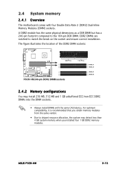
... is recommended that you installed four 1 GB DDR2 memory modules. The figure illustrates the location of the DDR2 DIMM sockets: 128 Pins P5CR-VM P5CR-VM 240-pin DDR2 DIMM sockets 112 Pins DIMM_A1 DIMM_A2 DIMM_B1 DIMM_B2 2.4.2 Memory configurations You may detect less than 4 GB system memory when ...DDR2 DIMMs into the DIMM sockets. • Always install DIMMs with four Double Data Rate 2 (DDR2) Dual Inline Memory Modules (DIMM) sockets. ASUS P5CR-VM 2-13 A DDR2 module has the same physical dimensions as a DDR DIMM but has a 240-pin footprint compared to match the break on the...
... is recommended that you installed four 1 GB DDR2 memory modules. The figure illustrates the location of the DDR2 DIMM sockets: 128 Pins P5CR-VM P5CR-VM 240-pin DDR2 DIMM sockets 112 Pins DIMM_A1 DIMM_A2 DIMM_B1 DIMM_B2 2.4.2 Memory configurations You may detect less than 4 GB system memory when ...DDR2 DIMMs into the DIMM sockets. • Always install DIMMs with four Double Data Rate 2 (DDR2) Dual Inline Memory Modules (DIMM) sockets. ASUS P5CR-VM 2-13 A DDR2 module has the same physical dimensions as a DDR DIMM but has a 240-pin footprint compared to match the break on the...

User Guide
Page 35
... settings. 1. Replace the system cover. 2.5.2 Configuring an expansion card After installing the expansion card, configure it and make the necessary hardware settings for later use . ASUS P5CR-VM 2-15 Make sure to use . 4. Align the card connector with the screw you removed earlier. 6. Turn on BIOS setup. 2. Otherwise, conflicts will arise between the...
... settings. 1. Replace the system cover. 2.5.2 Configuring an expansion card After installing the expansion card, configure it and make the necessary hardware settings for later use . ASUS P5CR-VM 2-15 Make sure to use . 4. Align the card connector with the screw you removed earlier. 6. Turn on BIOS setup. 2. Otherwise, conflicts will arise between the...
User Guide
Page 37
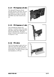
ASUS P5CR-VM 2-17 The figure shows a network card installed on the PCI Express x1 slot. 2.5.6 PCI slots The PCI slots support cards such as a LAN card, SCSI ...
ASUS P5CR-VM 2-17 The figure shows a network card installed on the PCI Express x1 slot. 2.5.6 PCI slots The PCI slots support cards such as a LAN card, SCSI ...

User Guide
Page 39
... current consumed must NOT exceed the power supply capability (+5VSB) whether under normal condition or in reduced power mode). USBPW12 21 32 +5V (Default) +5VSB P5CR-LS P5CR-VM USB device wake-up USBPW34 21 32 +5V (Default) +5VSB USBPW56 USBPW78 12 23 +5V (Default) +5VSB • The USB device wake-up the..., USBPW34, USBPW56, USBPW78) Set these jumpers to wake up feature requires a power supply that can provide 500mA on the +5VSB lead for each USB port; ASUS P5CR-VM 2-19 Set these jumpers to +5V to pins 1-2 if you are using the connected USB devices.
... current consumed must NOT exceed the power supply capability (+5VSB) whether under normal condition or in reduced power mode). USBPW12 21 32 +5V (Default) +5VSB P5CR-LS P5CR-VM USB device wake-up USBPW34 21 32 +5V (Default) +5VSB USBPW56 USBPW78 12 23 +5V (Default) +5VSB • The USB device wake-up the..., USBPW34, USBPW56, USBPW78) Set these jumpers to wake up feature requires a power supply that can provide 500mA on the +5VSB lead for each USB port; ASUS P5CR-VM 2-19 Set these jumpers to +5V to pins 1-2 if you are using the connected USB devices.
User Guide
Page 41
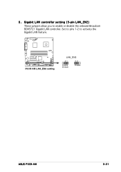
6 . Gigabit LAN controller setting (3-pin LAN_EN2) These jumpers allow you to activate the Gigabit LAN feature. P5CR-LS P5CR-VM LAN_EN2 setting LAN_EN2 21 32 Enable (Default) Disable ASUS P5CR-VM 2-21 Set to pins 1-2 to enable or disable the onboard Broadcom BCM5721 Gigabit LAN controller.
6 . Gigabit LAN controller setting (3-pin LAN_EN2) These jumpers allow you to activate the Gigabit LAN feature. P5CR-LS P5CR-VM LAN_EN2 setting LAN_EN2 21 32 Enable (Default) Disable ASUS P5CR-VM 2-21 Set to pins 1-2 to enable or disable the onboard Broadcom BCM5721 Gigabit LAN controller.

User Guide
Page 43
... No link Linked Data activity Status Description0 OFF 10 Mbps connection ORANGE 100 Mbps connection GREEN 1 Gbps connection ACT/LINK SPEED LED LED LAN port ASUS P5CR-VM 2-23 U S B 2 . 0 p o r t s 1 a n d 2 . Refer to a Local Area Network (LAN) through a network hub. P S / 2 m o u s e p o r t ( g r e e n ) . This port is for a PS/2 keyboard...
... No link Linked Data activity Status Description0 OFF 10 Mbps connection ORANGE 100 Mbps connection GREEN 1 Gbps connection ACT/LINK SPEED LED LED LAN port ASUS P5CR-VM 2-23 U S B 2 . 0 p o r t s 1 a n d 2 . Refer to a Local Area Network (LAN) through a network hub. P S / 2 m o u s e p o r t ( g r e e n ) . This port is for a PS/2 keyboard...

User Guide
Page 45
ASUS P5CR-VM 2-25 Refer to the hard disk documentation for the jumper settings. • Pin 20 on the IDE connector is for Ultra DMA 100/66 IDE ... install two hard disk drives, you connect the IDE cable. • Use the 80-conductor IDE cable for an Ultra DMA 100/66 signal cable. P5CR-VM P5CR-VM IDE connector PRI_IDE1 PIN 1 NOTE: Orient the red markings (usually zigzag) on the IDE ribbon cable to match the covered hole on the motherboard, a black...
ASUS P5CR-VM 2-25 Refer to the hard disk documentation for the jumper settings. • Pin 20 on the IDE connector is for Ultra DMA 100/66 IDE ... install two hard disk drives, you connect the IDE cable. • Use the 80-conductor IDE cable for an Ultra DMA 100/66 signal cable. P5CR-VM P5CR-VM IDE connector PRI_IDE1 PIN 1 NOTE: Orient the red markings (usually zigzag) on the IDE ribbon cable to match the covered hole on the motherboard, a black...

User Guide
Page 47
... the fan connectors! CPU_FAN1 CPU_FAN1 CPU_FAN2 FANOUT4 FANPWR2 GND GND FANPWR2 FANOUT4 CPU_FAN2 REAR_FAN1 REAR_FAN2 P5CR-VM FRNT_FAN1 FRNT_FAN2 REAR_FAN2 REAR_FAN1 Rotation +12V GND FRNT_FAN1 Rotation +12V GND FRNT_FAN2 P5CR-VM Fan connectors Rotation +12V GND Rotation +12V GND ASUS P5CR-VM 2-27 Insufficient air flow inside the system may damage the motherboard components. Do not place...
... the fan connectors! CPU_FAN1 CPU_FAN1 CPU_FAN2 FANOUT4 FANPWR2 GND GND FANPWR2 FANOUT4 CPU_FAN2 REAR_FAN1 REAR_FAN2 P5CR-VM FRNT_FAN1 FRNT_FAN2 REAR_FAN2 REAR_FAN1 Rotation +12V GND FRNT_FAN1 Rotation +12V GND FRNT_FAN2 P5CR-VM Fan connectors Rotation +12V GND Rotation +12V GND ASUS P5CR-VM 2-27 Insufficient air flow inside the system may damage the motherboard components. Do not place...
User Guide
Page 49
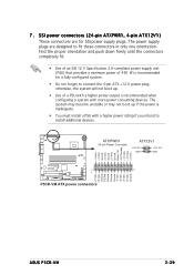
... Ground Power OK +5V Standby +12 Volts +12 Volts +3 Volts +3 Volts -12 Volts Ground PSON# Ground Ground Ground -5 Volts +5 Volts +5 Volts +5 Volts Ground 1 P5CR-VM P5CR-VM ATX power connectors ASUS P5CR-VM 2-29 S S I power connectors (24-pin ATXPWR1, 4- Find the proper orientation and push down firmly until the connectors completely fit. • Use of an SSI...
... Ground Power OK +5V Standby +12 Volts +12 Volts +3 Volts +3 Volts -12 Volts Ground PSON# Ground Ground Ground -5 Volts +5 Volts +5 Volts +5 Volts Ground 1 P5CR-VM P5CR-VM ATX power connectors ASUS P5CR-VM 2-29 S S I power connectors (24-pin ATXPWR1, 4- Find the proper orientation and push down firmly until the connectors completely fit. • Use of an SSI...
User Guide
Page 51
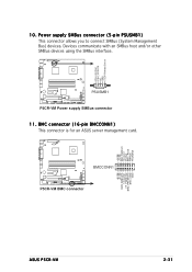
... you to connect SMBus (System Management Bus) devices. BMCCONN1 P5CR-VM P5CR-VM BMC connector +5VSB +5VSB BMC SMBCLK 12CCLK1 PSON# BMC_RST# PWROK PSONEN# +5VSB +5VSB BMC SMBDATA 12CDATA1 FP_PWRBTN# BMC_PRESENT# BMC_SMI# GND ASUS P5CR-VM 2-31 Devices communicate with an SMBus host and/or other ...SMBus devices using the SMBus interface. BMC connector (16-pin BMCCONN1) This connector is for an ASUS server management card. PSU_I2CCLK PSU_I2CDATA NC GND +3.3V ...
... you to connect SMBus (System Management Bus) devices. BMCCONN1 P5CR-VM P5CR-VM BMC connector +5VSB +5VSB BMC SMBCLK 12CCLK1 PSON# BMC_RST# PWROK PSONEN# +5VSB +5VSB BMC SMBDATA 12CDATA1 FP_PWRBTN# BMC_PRESENT# BMC_SMI# GND ASUS P5CR-VM 2-31 Devices communicate with an SMBus host and/or other ...SMBus devices using the SMBus interface. BMC connector (16-pin BMCCONN1) This connector is for an ASUS server management card. PSU_I2CCLK PSU_I2CDATA NC GND +3.3V ...
User Guide
Page 53
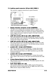
... event. • LAN1 link activity LED (2-pin LAN1_LINKACTLED) This 2-pin connector is for a chassis with an intrusion detection feature. ASUS P5CR-VM 2-33 13. AUX_PANEL1 P5CR-VM LAN2_LINKACTLEDLAN2_LINKACTLED+ LAN1_LINKACTLED+ LAN1_LINKACTLED- +5VSB I2CDATA_P0 GND I2CCLK_P0 NC P5CR-VM Auxiliary panel connector +5VSB AUX_BMCLOCLED# GND AUX_BMCLOCBNT# AUX_BMCLOCLED# AUX_LOCLED1 GND CASEOPEN +5VSB PIN1 • Chassis Intrusion connector (3-pin CASEOPEN) This...
... event. • LAN1 link activity LED (2-pin LAN1_LINKACTLED) This 2-pin connector is for a chassis with an intrusion detection feature. ASUS P5CR-VM 2-33 13. AUX_PANEL1 P5CR-VM LAN2_LINKACTLEDLAN2_LINKACTLED+ LAN1_LINKACTLED+ LAN1_LINKACTLED- +5VSB I2CDATA_P0 GND I2CCLK_P0 NC P5CR-VM Auxiliary panel connector +5VSB AUX_BMCLOCLED# GND AUX_BMCLOCBNT# AUX_BMCLOCLED# AUX_LOCLED1 GND CASEOPEN +5VSB PIN1 • Chassis Intrusion connector (3-pin CASEOPEN) This...


