
P4T User Manual
Page 1
® P4T Intel® 850 ATX Motherboard USER'S MANUAL
® P4T Intel® 850 ATX Motherboard USER'S MANUAL

P4T User Manual
Page 4
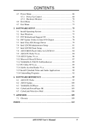
... 51 4.3.2 Keyboard Features 54 4.4 Advanced Menu 56 4.4.1 4.4.2 4.4.3 4.4.4 Chip Configuration 60 I/O Device Configuration 62 PCI Configuration 64 Shadow Configuration 65 4 ASUS P4T User's Manual HARDWARE SETUP 14 3.1 P4T Motherboard Layout 14 3.2 Layout Contents 15 3.3 Getting Started 16 3.4 Motherboard Settings 17 3.5 System Memory 22 3.5.1 Installing Memory 23 3.6 Central Processing Unit (CPU 24 3.6.1 CPU Installation 24 3.6.2 CPU Heatsink Retention...
... 51 4.3.2 Keyboard Features 54 4.4 Advanced Menu 56 4.4.1 4.4.2 4.4.3 4.4.4 Chip Configuration 60 I/O Device Configuration 62 PCI Configuration 64 Shadow Configuration 65 4 ASUS P4T User's Manual HARDWARE SETUP 14 3.1 P4T Motherboard Layout 14 3.2 Layout Contents 15 3.3 Getting Started 16 3.4 Motherboard Settings 17 3.5 System Memory 22 3.5.1 Installing Memory 23 3.6 Central Processing Unit (CPU 24 3.6.1 CPU Installation 24 3.6.2 CPU Heatsink Retention...
P4T User Manual
Page 5
... 71 4.7 Exit Menu 73 5. APPENDIX 109 7.1 Glossary 109 INDEX 113 ASUS P4T User's Manual 5 SOFTWARE REFERENCE 95 6.1 ASUS PC Probe 95 6.2 ASUS Update 100 6.3 YAMAHA XGPlayer 101 6.4 CyberLink PowerPlayer SE 105 6.5 CyberLink VideoLive Mail 106 7. SOFTWARE SETUP 75 5.1 Install Operating System 75 5.2 Start Windows 75 5.3 P4T Motherboard Support CD 76 5.4 INF Update Utility for Intel 850 Chipset...
... 71 4.7 Exit Menu 73 5. APPENDIX 109 7.1 Glossary 109 INDEX 113 ASUS P4T User's Manual 5 SOFTWARE REFERENCE 95 6.1 ASUS PC Probe 95 6.2 ASUS Update 100 6.3 YAMAHA XGPlayer 101 6.4 CyberLink PowerPlayer SE 105 6.5 CyberLink VideoLive Mail 106 7. SOFTWARE SETUP 75 5.1 Install Operating System 75 5.2 Start Windows 75 5.3 P4T Motherboard Support CD 76 5.4 INF Update Utility for Intel 850 Chipset...
P4T User Manual
Page 7
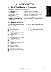
... USB connector set with bracket (1) I/O port bracket (1) Bag of spare jumpers (1) Support drivers and utilities (1) This Motherboard User's Manual (1) CPU Heatsink Retention Module Optional Items ASUS IrDA-compliant infrared module ASUS P4T User's Manual 7 FEATURES 3. HARDWARE SETUP 4. If you discover damaged or missing items, contact your package is divided into the following sections: 1. INTRODUCTION 2. BIOS SETUP...
... USB connector set with bracket (1) I/O port bracket (1) Bag of spare jumpers (1) Support drivers and utilities (1) This Motherboard User's Manual (1) CPU Heatsink Retention Module Optional Items ASUS IrDA-compliant infrared module ASUS P4T User's Manual 7 FEATURES 3. HARDWARE SETUP 4. If you discover damaged or missing items, contact your package is divided into the following sections: 1. INTRODUCTION 2. BIOS SETUP...
P4T User Manual
Page 8
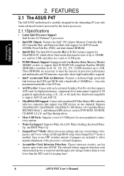
...96, 128, 192, 256, 512MB densities) up to allow manual adjustment of 266MB/sec - These RDRAMs are included to 100MB/ sec; and two USB controllers for keeping time! 8 ASUS P4T User's Manual The onboard battery supports detection even when normal power is removed and...external frequency. • Around-the-Clock Intrusion Detection: Chassis intrusion circuitry can log chassis open events into LDCM. FEATURES 2.1 The ASUS P4T The ASUS P4T motherboard is required. • Intel® Accelerated Hub Architecture: Features a dedicated high speed hub link between the ICH2 and MCH with...
...96, 128, 192, 256, 512MB densities) up to allow manual adjustment of 266MB/sec - These RDRAMs are included to 100MB/ sec; and two USB controllers for keeping time! 8 ASUS P4T User's Manual The onboard battery supports detection even when normal power is removed and...external frequency. • Around-the-Clock Intrusion Detection: Chassis intrusion circuitry can log chassis open events into LDCM. FEATURES 2.1 The ASUS P4T The ASUS P4T motherboard is required. • Intel® Accelerated Hub Architecture: Features a dedicated high speed hub link between the ICH2 and MCH with...
P4T User Manual
Page 9
... a reminder to the user to turn OFF the power before plugging and unplugging devices so as not to damage the motherboard, peripherals, and/or components. • Integrated LAN Capability (optional): Features the Intel ICH2 integrated LAN controller, which ...; Concurrent PCI: Concurrent PCI allows multiple PCI transfers from COM2 to the motherboard. FEATURES • SMBus: Features the System Management Bus interface, which provides more control and protection over the motherboard. ASUS P4T User's Manual 9 Provides Vcore and CPU/ RDRAM frequency adjustments, boot block write protection,...
... a reminder to the user to turn OFF the power before plugging and unplugging devices so as not to damage the motherboard, peripherals, and/or components. • Integrated LAN Capability (optional): Features the Intel ICH2 integrated LAN controller, which ...; Concurrent PCI: Concurrent PCI allows multiple PCI transfers from COM2 to the motherboard. FEATURES • SMBus: Features the System Management Bus interface, which provides more control and protection over the motherboard. ASUS P4T User's Manual 9 Provides Vcore and CPU/ RDRAM frequency adjustments, boot block write protection,...
P4T User Manual
Page 10
...Concurrent PCI: Concurrent PCI allows multiple PCI transfers from PCI master buses to memory and processor. • RDRAM Optimized Performance: This motherboard supports the new generation memory, Rambus Dynamic Random Access Memory (RDRAM). FEATURES 2.1.2 Performance • High-Speed Data Transfer Interface: Onboard...all ASUS smart series motherboards. ACPI provides more Energy Saving Features for Windows 95/NT and later. Supports UltraDMA/100/66, UltraDMA/33 (IDE DMA Mode 2), PIO Modes 3 & 4, and supports Enhanced IDE devices, such as required by PC 99. 10 ASUS P4T User's Manual ...
...Concurrent PCI: Concurrent PCI allows multiple PCI transfers from PCI master buses to memory and processor. • RDRAM Optimized Performance: This motherboard supports the new generation memory, Rambus Dynamic Random Access Memory (RDRAM). FEATURES 2.1.2 Performance • High-Speed Data Transfer Interface: Onboard...all ASUS smart series motherboards. ACPI provides more Energy Saving Features for Windows 95/NT and later. Supports UltraDMA/100/66, UltraDMA/33 (IDE DMA Mode 2), PIO Modes 3 & 4, and supports Enhanced IDE devices, such as required by PC 99. 10 ASUS P4T User's Manual ...
P4T User Manual
Page 11
...• System Resources Alert: Today's operating systems, such as the "Stand by" (a.k.a. ASUS P4T User's Manual 11 FEATURES 2.1.3 Intelligence • Auto CPU Throttling Function: Incorporated into this motherboard supports processor thermal sensing and auto-protection. • Voltage Monitoring and Alert: System voltage levels...alarm thresholds. • Temperature Monitoring andAlert: To prevent system overheat and system damage, this motherboard is enabled, the CPU with either the bundled ASUS PC Probe or Intel LDCM will warn the user before the system resources are used up ...
...• System Resources Alert: Today's operating systems, such as the "Stand by" (a.k.a. ASUS P4T User's Manual 11 FEATURES 2.1.3 Intelligence • Auto CPU Throttling Function: Incorporated into this motherboard supports processor thermal sensing and auto-protection. • Voltage Monitoring and Alert: System voltage levels...alarm thresholds. • Temperature Monitoring andAlert: To prevent system overheat and system damage, this motherboard is enabled, the CPU with either the bundled ASUS PC Probe or Intel LDCM will warn the user before the system resources are used up ...
P4T User Manual
Page 12
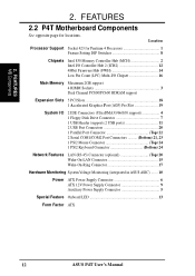
FEATURES MB Components 2. Location Processor Support Socket 423 for locations. 2. FEATURES 2.2 P4T Motherboard Components See opposite page for Pentium 4 Processors 1 Feature Setting DIP Switches 8 Chipsets Intel 850 Memory Controller Hub (MCH 2 Intel I/O...) 20 Wake-On-LAN Connector 15 Wake-On-Ring Connector 17 Hardware Monitoring System Voltage Monitoring (integrated in ASUS ASIC) ....... 10 Power ATX Power Supply Connector 6 ATX 12V Power Supply Connector 9 Auxiliary Power Supply Connector 5 Special Feature Onboard LED 13 Form Factor ATX 12 ASUS P4T User's Manual
FEATURES MB Components 2. Location Processor Support Socket 423 for locations. 2. FEATURES 2.2 P4T Motherboard Components See opposite page for Pentium 4 Processors 1 Feature Setting DIP Switches 8 Chipsets Intel 850 Memory Controller Hub (MCH 2 Intel I/O...) 20 Wake-On-LAN Connector 15 Wake-On-Ring Connector 17 Hardware Monitoring System Voltage Monitoring (integrated in ASUS ASIC) ....... 10 Power ATX Power Supply Connector 6 ATX 12V Power Supply Connector 9 Auxiliary Power Supply Connector 5 Special Feature Onboard LED 13 Form Factor ATX 12 ASUS P4T User's Manual
P4T User Manual
Page 14
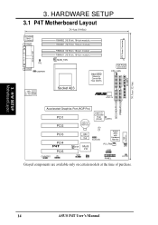
HARDWARE SETUP 3.1 P4T Motherboard Layout 24.4cm (9.60in) PS/2KBMS T: Mouse B: Keyboard COM1 PARALLEL PORT COM2 TR2 USBPWR RIMMB2 (16/18 bit, 184-pin module) RIMMB1 (16/18 bit, ... Hub (ICH2) CLRTC LED PCI3 PCI4 P4T PCI5 DIP Switches 4Mbit Firmware Hub SCSILED ASUS ASIC with Hardware Monitor WOR Multi I/O PCI_FAN JEN USB2 CHASSIS IR SMB WOL PANEL HDDLED Grayed components are available only on certain models at the time of purchase. 14 ASUS P4T User's Manual H/W SETUP Motherboard Layout 3. SECONDARY IDE PRIMARY IDE FLOPPY...
HARDWARE SETUP 3.1 P4T Motherboard Layout 24.4cm (9.60in) PS/2KBMS T: Mouse B: Keyboard COM1 PARALLEL PORT COM2 TR2 USBPWR RIMMB2 (16/18 bit, 184-pin module) RIMMB1 (16/18 bit, ... Hub (ICH2) CLRTC LED PCI3 PCI4 P4T PCI5 DIP Switches 4Mbit Firmware Hub SCSILED ASUS ASIC with Hardware Monitor WOR Multi I/O PCI_FAN JEN USB2 CHASSIS IR SMB WOL PANEL HDDLED Grayed components are available only on certain models at the time of purchase. 14 ASUS P4T User's Manual H/W SETUP Motherboard Layout 3. SECONDARY IDE PRIMARY IDE FLOPPY...
P4T User Manual
Page 15
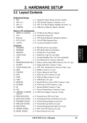
H/W SETUP Layout Contents 3. HARDWARE SETUP 3.2 Layout Contents Motherboard Settings 1) JEN 2) SW1 6-10 3) SW1 1-4 4) USBPWR p. 17 JumperFree Mode Setting (Disable / Enable) p. 18 CPU External Frequency (Switches 6-10) p. 20 CPU Core: Bus Frequency Multiple (Switches 1-4) p. ... (PANEL) p. 39 System Management Interrupt Lead (2 pin) 25) PWRSW (PANEL) p. 39 ATX / Soft-Off Switch Lead (2 pin) 26) RESET (PANEL) p. 39 Reset Switch Lead (2 pin) ASUS P4T User's Manual 15 3.
H/W SETUP Layout Contents 3. HARDWARE SETUP 3.2 Layout Contents Motherboard Settings 1) JEN 2) SW1 6-10 3) SW1 1-4 4) USBPWR p. 17 JumperFree Mode Setting (Disable / Enable) p. 18 CPU External Frequency (Switches 6-10) p. 20 CPU Core: Bus Frequency Multiple (Switches 1-4) p. ... (PANEL) p. 39 System Management Interrupt Lead (2 pin) 25) PWRSW (PANEL) p. 39 ATX / Soft-Off Switch Lead (2 pin) 26) RESET (PANEL) p. 39 Reset Switch Lead (2 pin) ASUS P4T User's Manual 15 3.
P4T User Manual
Page 16
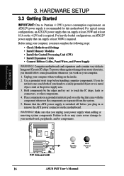
...Ensure that can supply at least 230W and at least 300W is recommended for this motherboard. H/W SETUP Motherboard Settings ® P4T P4T Onboard LED ON Standby Power OFF Powered Off 16 ASUS P4T User's Manual HARDWARE SETUP 3.3 Getting Started IMPORTANT: Due to touch the IC chips, leads or ... components are separated from static electricity, you should follow some precautions whenever you must complete the following steps: • Check Motherboard Settings • Install Memory Modules • Install the Central Processing Unit (CPU) • Install Expansion Cards • ...
...Ensure that can supply at least 230W and at least 300W is recommended for this motherboard. H/W SETUP Motherboard Settings ® P4T P4T Onboard LED ON Standby Power OFF Powered Off 16 ASUS P4T User's Manual HARDWARE SETUP 3.3 Getting Started IMPORTANT: Due to touch the IC chips, leads or ... components are separated from static electricity, you should follow some precautions whenever you must complete the following steps: • Check Motherboard Settings • Install Memory Modules • Install the Central Processing Unit (CPU) • Install Expansion Cards • ...
P4T User Manual
Page 17
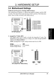
H/W SETUP Motherboard Settings 3. Frequency Multiple 3. Frequency Selection 10. Frequency Multiple 5. Frequency Selection 9. The illustration below shows all dip ... 5 6 7 8 9 10 ® P4T P4T JumperFree™ Mode Setting Jumper JumperFree 12 23 JEN ASUS P4T User's Manual 17 ON 1 2 3 4 5 6 7 8 9 10 3. NOTE: In JumperFree™ mode, all the switches in the OFF position. ® P4T P4T DIP Switches SW1 ON OFF 1. HARDWARE SETUP 3.4 Motherboard Settings Motherboard Frequency Settings (DIP Switches) The motherboard frequency is adjusted through the BIOS...
H/W SETUP Motherboard Settings 3. Frequency Multiple 3. Frequency Selection 10. Frequency Multiple 5. Frequency Selection 9. The illustration below shows all dip ... 5 6 7 8 9 10 ® P4T P4T JumperFree™ Mode Setting Jumper JumperFree 12 23 JEN ASUS P4T User's Manual 17 ON 1 2 3 4 5 6 7 8 9 10 3. NOTE: In JumperFree™ mode, all the switches in the OFF position. ® P4T P4T DIP Switches SW1 ON OFF 1. HARDWARE SETUP 3.4 Motherboard Settings Motherboard Frequency Settings (DIP Switches) The motherboard frequency is adjusted through the BIOS...
P4T User Manual
Page 18
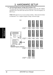
... 41.7MHz 128.0MHz 42.7MHz ON 1 2 3 4 5 6 7 8 9 10 ON 1 2 3 4 5 6 7 8 9 10 CPU/DRAM → 130.0MHz 133.0MHz PCI BUS → 43.30MHz 44.3MHz 18 ASUS P4T User's Manual For a complete frequency listing, see the next page. H/W SETUP Motherboard Settings 3. Only selected switches are illustrated.
... 41.7MHz 128.0MHz 42.7MHz ON 1 2 3 4 5 6 7 8 9 10 ON 1 2 3 4 5 6 7 8 9 10 CPU/DRAM → 130.0MHz 133.0MHz PCI BUS → 43.30MHz 44.3MHz 18 ASUS P4T User's Manual For a complete frequency listing, see the next page. H/W SETUP Motherboard Settings 3. Only selected switches are illustrated.
P4T User Manual
Page 19
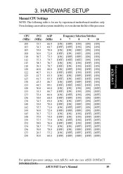
Overclocking can result in system instability or even shorten the life of the processor. HARDWARE SETUP Manual CPU Settings NOTE: The following table is for use by experienced motherboard installers only. CPU (MHz) 100 103 105 108 110 112 115 118 120 122 125 125 130 133 120 133 133 136 138 140...] [ON] [ON] [ON] [ON] [OFF] [OFF] [OFF] [OFF] [OFF] [OFF] [OFF] [OFF] [OFF] [OFF] [OFF] [OFF] [OFF] [OFF] [OFF] [OFF] For updated processor settings, visit ASUS's web site (see ASUS CONTACT INFORMATION) ASUS P4T User's Manual 19 3. H/W SETUP Motherboard Settings 3.
Overclocking can result in system instability or even shorten the life of the processor. HARDWARE SETUP Manual CPU Settings NOTE: The following table is for use by experienced motherboard installers only. CPU (MHz) 100 103 105 108 110 112 115 118 120 122 125 125 130 133 120 133 133 136 138 140...] [ON] [ON] [ON] [ON] [OFF] [OFF] [OFF] [OFF] [OFF] [OFF] [OFF] [OFF] [OFF] [OFF] [OFF] [OFF] [OFF] [OFF] [OFF] [OFF] For updated processor settings, visit ASUS's web site (see ASUS CONTACT INFORMATION) ASUS P4T User's Manual 19 3. H/W SETUP Motherboard Settings 3.
P4T User Manual
Page 20
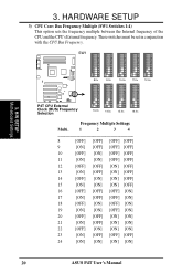
H/W SETUP Motherboard Settings ® 8.0x 9.0x 10.0x 11.0x 12.0x ON 1 2 3 4 5 6 7 8 9 10 ON 1 2 3 4 5 6 7 8 9 10 ON 1 2 3 4 5 6 7 8 9 10 ON 1 2 3 4 5 6 7 8 9 10 P4T P4T CPU External Clock (BUS) Frequency Selection 13.0x 14.0x 15.0x 16.0x Frequency Multiple Settings Multi. 1 2 3 4 8 [OFF] [OFF...[ON] [ON] 22 [OFF] [ON] [ON] [ON] 23 [ON] [OFF] [OFF] [OFF] 24 [ON] [ON] [ON] [ON] 20 ASUS P4T User's Manual HARDWARE SETUP 3) CPU Core: Bus Frequency Multiple (SW1 Switches 1-4) This option sets the frequency multiple between the Internal frequency of the CPU and the CPU...
H/W SETUP Motherboard Settings ® 8.0x 9.0x 10.0x 11.0x 12.0x ON 1 2 3 4 5 6 7 8 9 10 ON 1 2 3 4 5 6 7 8 9 10 ON 1 2 3 4 5 6 7 8 9 10 ON 1 2 3 4 5 6 7 8 9 10 P4T P4T CPU External Clock (BUS) Frequency Selection 13.0x 14.0x 15.0x 16.0x Frequency Multiple Settings Multi. 1 2 3 4 8 [OFF] [OFF...[ON] [ON] 22 [OFF] [ON] [ON] [ON] 23 [ON] [OFF] [OFF] [OFF] 24 [ON] [ON] [ON] [ON] 20 ASUS P4T User's Manual HARDWARE SETUP 3) CPU Core: Bus Frequency Multiple (SW1 Switches 1-4) This option sets the frequency multiple between the Internal frequency of the CPU and the CPU...
P4T User Manual
Page 21
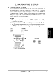
NOTES: 1. H/W SETUP Motherboard Settings ASUS P4T User's Manual 21 Setting Disable Enable USBPWR [2-3] (default) [1-2] ® P4T P4T USB Device Wake Up USBPWR 12 23 Enable Disable (Default) 3. Set this jumper must NOT exceed the power supply capability (+5VSB) whether under normal working ...
NOTES: 1. H/W SETUP Motherboard Settings ASUS P4T User's Manual 21 Setting Disable Enable USBPWR [2-3] (default) [1-2] ® P4T P4T USB Device Wake Up USBPWR 12 23 Enable Disable (Default) 3. Set this jumper must NOT exceed the power supply capability (+5VSB) whether under normal working ...
P4T User Manual
Page 22
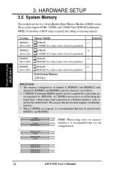
...) must be populated) Total System Memory (2GB Max) IMPORTANT 1. a. This assures that are required, it is recommended that you use 128MB RDRAM RIMMA1 configuration a. H/W SETUP Motherboard Settings 3. Location RIMMA1 (Rows 0&1) Memory Module RDRAM C-RIMM (Use when socket will not be populated) Subtotal x 1 RIMMA2 (Rows 2&3) RIMMB1 (Rows 4&5) RDRAM x1 C-RIMM (... Rambus interface. 3. b. 128MB RDRAM RIMMB2 C-RIMM RIMMB1 128MB RDRAM C-RIMM RIMMA2 RIMMA1 c. 128MB RDRAM RIMMB2 128MB RDRAM RIMMB1 128MB RDRAM 128MB RDRAM RIMMA2 RIMMA1 22 ASUS P4T User's Manual
...) must be populated) Total System Memory (2GB Max) IMPORTANT 1. a. This assures that are required, it is recommended that you use 128MB RDRAM RIMMA1 configuration a. H/W SETUP Motherboard Settings 3. Location RIMMA1 (Rows 0&1) Memory Module RDRAM C-RIMM (Use when socket will not be populated) Subtotal x 1 RIMMA2 (Rows 2&3) RIMMB1 (Rows 4&5) RDRAM x1 C-RIMM (... Rambus interface. 3. b. 128MB RDRAM RIMMB2 C-RIMM RIMMB1 128MB RDRAM C-RIMM RIMMA2 RIMMA1 c. 128MB RDRAM RIMMB2 128MB RDRAM RIMMB1 128MB RDRAM 128MB RDRAM RIMMA2 RIMMA1 22 ASUS P4T User's Manual
P4T User Manual
Page 23
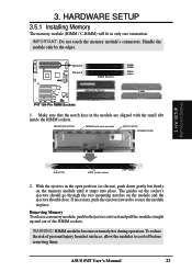
Channel B Channel A ® RIMM Sockets RIMMB2 RIMMB1 RIMMA2 RIMMA1 P4T P4T 184-Pin RIMM Sockets RIMM with heat spreader) NOTCH KEYS CONNECTORS 3. MOUNTING NOTCH RDRAM (with Heat Spreader C-RIMM 1. The guides on the socket's ejectors ... H/W SETUP Motherboard Settings EJECTOR RIBS (inside the RIMM sockets. To reduce the risk of the RIMM sockets. HARDWARE SETUP 3.5.1 Installing Memory The memory module (RIMM / C-RIMM) will fit in the module are aligned with the small ribs inside socket) (TOP VIEW) 2. Handle the module only by the edges. ASUS P4T User's Manual 23 3. Make...
Channel B Channel A ® RIMM Sockets RIMMB2 RIMMB1 RIMMA2 RIMMA1 P4T P4T 184-Pin RIMM Sockets RIMM with heat spreader) NOTCH KEYS CONNECTORS 3. MOUNTING NOTCH RDRAM (with Heat Spreader C-RIMM 1. The guides on the socket's ejectors ... H/W SETUP Motherboard Settings EJECTOR RIBS (inside the RIMM sockets. To reduce the risk of the RIMM sockets. HARDWARE SETUP 3.5.1 Installing Memory The memory module (RIMM / C-RIMM) will fit in the module are aligned with the small ribs inside socket) (TOP VIEW) 2. Handle the module only by the edges. ASUS P4T User's Manual 23 3. Make...

P4T User Manual
Page 24
HARDWARE SETUP 3.6 Central Processing Unit (CPU) The motherboard provides a ZIF Socket for bent pins. 24 ASUS P4T User's Manual Locate the P4 Socket 423 and open it snaps into the socket to prevent overheating. The gold arrow of the CPU must be oriented toward ... base nearest to 100 degrees). 2. The socket lever must be fully opened (90 to the tip of the lever handle. 3. Insert the CPU with the motherboard should drop easily into place. Do not force the CPU into its alignment and look for the P4 Socket 423 CPU. If not, then purchase...
HARDWARE SETUP 3.6 Central Processing Unit (CPU) The motherboard provides a ZIF Socket for bent pins. 24 ASUS P4T User's Manual Locate the P4 Socket 423 and open it snaps into the socket to prevent overheating. The gold arrow of the CPU must be oriented toward ... base nearest to 100 degrees). 2. The socket lever must be fully opened (90 to the tip of the lever handle. 3. Insert the CPU with the motherboard should drop easily into place. Do not force the CPU into its alignment and look for the P4 Socket 423 CPU. If not, then purchase...


