

Motherboard DIY Troubleshooting Guide
Page 20
Rubber Pad Metal Baseboard 9=IDAH Motherboard Copper captive nut ® Motherboard Washer 20
Rubber Pad Metal Baseboard 9=IDAH Motherboard Copper captive nut ® Motherboard Washer 20

Motherboard DIY Troubleshooting Guide
Page 87
LEDs RJ45 LAN Activity Output Signal Intel Chipset Wake on LAN Output Signal ASUS Motherboard type Other 87
LEDs RJ45 LAN Activity Output Signal Intel Chipset Wake on LAN Output Signal ASUS Motherboard type Other 87

P4T-M User Manual
Page 1
® P4T-M Intel® 850 Micro-ATX Motherboard USER'S MANUAL ASUS P4T-M User's Manual 1
® P4T-M Intel® 850 Micro-ATX Motherboard USER'S MANUAL ASUS P4T-M User's Manual 1

P4T-M User Manual
Page 4
FEATURES 8 2.1 The ASUS P4T-M 8 2.2 P4T-M Motherboard Components 12 3. BIOS SETUP 39 4.1 Managing and Updating Your BIOS 39 4.1.1 Upon First Use of the Computer System 39 ... Configuration 56 4.4.3 PCI Configuration 58 4.4.4 Shadow Configuration 60 4.5 Power Menu 61 4.5.1 Power Up Control 63 4 ASUS P4T-M User's Manual CONTENTS 1. INTRODUCTION 7 1.1 How This Manual Is Organized 7 1.2 Item Checklist 7 2. HARDWARE SETUP 14 3.1 P4T-M Motherboard Layout 14 3.2 Layout Contents 15 3.3 Getting Started 16 3.4 System Memory 17 3.5.1 CPU Installation 19 3.5 Central Processing...
FEATURES 8 2.1 The ASUS P4T-M 8 2.2 P4T-M Motherboard Components 12 3. BIOS SETUP 39 4.1 Managing and Updating Your BIOS 39 4.1.1 Upon First Use of the Computer System 39 ... Configuration 56 4.4.3 PCI Configuration 58 4.4.4 Shadow Configuration 60 4.5 Power Menu 61 4.5.1 Power Up Control 63 4 ASUS P4T-M User's Manual CONTENTS 1. INTRODUCTION 7 1.1 How This Manual Is Organized 7 1.2 Item Checklist 7 2. HARDWARE SETUP 14 3.1 P4T-M Motherboard Layout 14 3.2 Layout Contents 15 3.3 Getting Started 16 3.4 System Memory 17 3.5.1 CPU Installation 19 3.5 Central Processing...

P4T-M User Manual
Page 5
CONTENTS 4.5.2 Hardware Monitor 64 4.6 Boot Menu 65 4.7 Exit Menu 67 5. APPENDIX 81 7.1 Glossary 81 INDEX 85 ASUS P4T-M User's Manual 5 SOFTWARE REFERENCE 73 6.2 ASUS PC Probe 73 6.3 CyberLink PowerPlayer SE 78 6.4 CyberLink VideoLive Mail 79 7. SOFTWARE SETUP 69 5.1 Install Operating System 69 5.2 Start Windows 69 5.3 P4T-M Motherboard Support CD 70 6.1 ASUS Live Update 72 6.
CONTENTS 4.5.2 Hardware Monitor 64 4.6 Boot Menu 65 4.7 Exit Menu 67 5. APPENDIX 81 7.1 Glossary 81 INDEX 85 ASUS P4T-M User's Manual 5 SOFTWARE REFERENCE 73 6.2 ASUS PC Probe 73 6.3 CyberLink PowerPlayer SE 78 6.4 CyberLink VideoLive Mail 79 7. SOFTWARE SETUP 69 5.1 Install Operating System 69 5.2 Start Windows 69 5.3 P4T-M Motherboard Support CD 70 6.1 ASUS Live Update 72 6.
P4T-M User Manual
Page 7
... USB connector set with bracket (1) I/O port bracket (1) Bag of spare jumpers (1) Support drivers and utilities (1) This Motherboard User's Manual (1) CPU Heatsink Retention Module (1) Quick Setup Manual (1) Reference Card Optional Items ASUS IrDA-compliant infrared module ASUS P4T-M User's Manual 7 FEATURES 3. BIOS SETUP 5. SOFTWARE REFERENCE 7. APPENDIX Manual information and checklist Production information and specifications Intructions...
... USB connector set with bracket (1) I/O port bracket (1) Bag of spare jumpers (1) Support drivers and utilities (1) This Motherboard User's Manual (1) CPU Heatsink Retention Module (1) Quick Setup Manual (1) Reference Card Optional Items ASUS IrDA-compliant infrared module ASUS P4T-M User's Manual 7 FEATURES 3. BIOS SETUP 5. SOFTWARE REFERENCE 7. APPENDIX Manual information and checklist Production information and specifications Intructions...

P4T-M User Manual
Page 8
... /O Controller Hub, and Firmware Hub) with an Accelerated Graphics Port 4X slot that support four IDE devices on two channels. FEATURES 2.1 The ASUS P4T-M The ASUS P4T-M motherboard is required. • Intel® Accelerated Hub Architecture: Features a dedicated high speed hub link between the ICH2 and MCH with a bandwidth ... slot is keyed to meet the increase in 64, 96, 128, 192, 256, 512MB densities) up to 133MB/s maximum throughput.) 8 ASUS P4T-M User's Manual twice the maximum bandwidth of 266MB/sec - These RDRAMs are necessary to support only the latest 1.5 volt AGP cards...
... /O Controller Hub, and Firmware Hub) with an Accelerated Graphics Port 4X slot that support four IDE devices on two channels. FEATURES 2.1 The ASUS P4T-M The ASUS P4T-M motherboard is required. • Intel® Accelerated Hub Architecture: Features a dedicated high speed hub link between the ICH2 and MCH with a bandwidth ... slot is keyed to meet the increase in 64, 96, 128, 192, 256, 512MB densities) up to 133MB/s maximum throughput.) 8 ASUS P4T-M User's Manual twice the maximum bandwidth of 266MB/sec - These RDRAMs are necessary to support only the latest 1.5 volt AGP cards...

P4T-M User Manual
Page 9
... available interface for virtually automatic setup. • Smart BIOS: 4Mbit firmware gives a new easy-to-use interface which provides more control and protection over the motherboard. ASUS P4T-M User's Manual 9 Provides Vcore and CPU/ RDRAM frequency adjustments, boot block write protection, and HD/SCSI/MO/ ZIP/CD/Floppy boot selection. • IrDA: Supports...
... available interface for virtually automatic setup. • Smart BIOS: 4Mbit firmware gives a new easy-to-use interface which provides more control and protection over the motherboard. ASUS P4T-M User's Manual 9 Provides Vcore and CPU/ RDRAM frequency adjustments, boot block write protection, and HD/SCSI/MO/ ZIP/CD/Floppy boot selection. • IrDA: Supports...
P4T-M User Manual
Page 10
... following high-level goals: support for Plug and Play compatibility and power management for systems and components are based on all ASUS smart series motherboards. UltraDMA/100 is backward compatible with DMA/66, DMA/33, and DMA and with a peak bandwidth of 0.8GB/s, ...be enabled.) • RDRAM Optimized Performance: This motherboard supports the new generation memory, Rambus Dynamic Random Access Memory (RDRAM). 2. Supports UltraDMA/100/66, UltraDMA/33 (IDE DMA Mode 2), PIO Modes 3 & 4, and supports Enhanced IDE devices, such as required by PC 99. 10 ASUS P4T-M User's Manual
... following high-level goals: support for Plug and Play compatibility and power management for systems and components are based on all ASUS smart series motherboards. UltraDMA/100 is backward compatible with DMA/66, DMA/33, and DMA and with a peak bandwidth of 0.8GB/s, ...be enabled.) • RDRAM Optimized Performance: This motherboard supports the new generation memory, Rambus Dynamic Random Access Memory (RDRAM). 2. Supports UltraDMA/100/66, UltraDMA/33 (IDE DMA Mode 2), PIO Modes 3 & 4, and supports Enhanced IDE devices, such as required by PC 99. 10 ASUS P4T-M User's Manual
P4T-M User Manual
Page 11
... LDCM will enter the Soft-Off mode. • Peripheral Power Up: Keyboard or Mouse power up to critical motherboard components. The onboard hardware ASUS ASIC in 3.8 Connectors for more than 4 seconds will warn the user before the system resources are monitored to ...100% of the setting, pushing the power button for more critical for RPM and failure. ASUS P4T-M User's Manual 11 FEATURES 2.1.4 Intelligence • Auto CPU Throttling Function: Incorporated into this motherboard supports processor thermal sensing and auto-protection. • Voltage Monitoring and Alert: System voltage...
... LDCM will enter the Soft-Off mode. • Peripheral Power Up: Keyboard or Mouse power up to critical motherboard components. The onboard hardware ASUS ASIC in 3.8 Connectors for more than 4 seconds will warn the user before the system resources are monitored to ...100% of the setting, pushing the power button for more critical for RPM and failure. ASUS P4T-M User's Manual 11 FEATURES 2.1.4 Intelligence • Auto CPU Throttling Function: Incorporated into this motherboard supports processor thermal sensing and auto-protection. • Voltage Monitoring and Alert: System voltage...

P4T-M User Manual
Page 12
Location Processor Support Socket 423 for locations. FEATURES 2.2 P4T-M Motherboard Components See opposite page for Pentium 4 Processors 1 Chipsets Intel 850 Memory Controller Hub (MCH 2 Intel I/O Controller Hub 2 (ICH2 11 4Mbit Firmware Hub (FWH 9 Yamaha Audio ... Pin Count (LPC) Winbond Multi-I/O Chipset 4 Power ATX Power Supply Connector 6 ATX 12V Power Supply Connector 6 Special Feature 1 iPanel AFPANEL Header 8 Form Factor MicroATX 12 ASUS P4T-M User's Manual FEATURES MB Components 2. 2.
Location Processor Support Socket 423 for locations. FEATURES 2.2 P4T-M Motherboard Components See opposite page for Pentium 4 Processors 1 Chipsets Intel 850 Memory Controller Hub (MCH 2 Intel I/O Controller Hub 2 (ICH2 11 4Mbit Firmware Hub (FWH 9 Yamaha Audio ... Pin Count (LPC) Winbond Multi-I/O Chipset 4 Power ATX Power Supply Connector 6 ATX 12V Power Supply Connector 6 Special Feature 1 iPanel AFPANEL Header 8 Form Factor MicroATX 12 ASUS P4T-M User's Manual FEATURES MB Components 2. 2.

P4T-M User Manual
Page 14
...module) RIMMA2 (16/18 bit, 184-pin module) RIMMA1 (16/18 bit, 184-pin module) 3. PRIMARY IDE FLOPPY 24.4cm (9.6in) 14 ASUS P4T-M User's Manual HARDWARE SETUP 3.1 P4T-M Motherboard Layout PS/2KBMS T: Mouse B: Keyboard Bottom: Top: USB1 RJ-45 USB2 COM1 24.4cm (9.60in) CPU_FAN Multi I/O ATX12V ATX Power Connector PARALLEL ... 1394 Link Layer Chip CR2032 3V Lithium Cell CMOS Power Intel I/O Controller Hub (ICH2) 4Mbit Firmware Hub CHA_FAN IR BUZZER CLRTC USB2 AFPANEL P4T-M COM2 IDELED PANEL Grayed components are available only on certain models at the time of purchase.
...module) RIMMA2 (16/18 bit, 184-pin module) RIMMA1 (16/18 bit, 184-pin module) 3. PRIMARY IDE FLOPPY 24.4cm (9.6in) 14 ASUS P4T-M User's Manual HARDWARE SETUP 3.1 P4T-M Motherboard Layout PS/2KBMS T: Mouse B: Keyboard Bottom: Top: USB1 RJ-45 USB2 COM1 24.4cm (9.60in) CPU_FAN Multi I/O ATX12V ATX Power Connector PARALLEL ... 1394 Link Layer Chip CR2032 3V Lithium Cell CMOS Power Intel I/O Controller Hub (ICH2) 4Mbit Firmware Hub CHA_FAN IR BUZZER CLRTC USB2 AFPANEL P4T-M COM2 IDELED PANEL Grayed components are available only on certain models at the time of purchase.

P4T-M User Manual
Page 16
... cause severe damage to your hands to a safely grounded object or to do not have one, touch both of your motherboard, peripherals, and/or components. 16 ASUS P4T-M User's Manual Failure to a metal object, such as the power supply case. 3. For typical system configurations, an ...connector on your power supply when adding or removing system components. WARNING! To protect them against damage from the system. 5. Computer motherboards and expansion cards contain very delicate Integrated Circuit (IC) chips. Make sure that came with the component whenever the components are ...
... cause severe damage to your hands to a safely grounded object or to do not have one, touch both of your motherboard, peripherals, and/or components. 16 ASUS P4T-M User's Manual Failure to a metal object, such as the power supply case. 3. For typical system configurations, an ...connector on your power supply when adding or removing system components. WARNING! To protect them against damage from the system. 5. Computer motherboards and expansion cards contain very delicate Integrated Circuit (IC) chips. Make sure that came with the component whenever the components are ...
P4T-M User Manual
Page 17
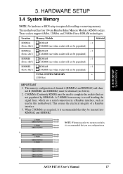
...RDRAM 128MB RDRAM RIMMA2 RIMMA1 ASUS P4T-M User's Manual 17 The memory configuration of a Rambus interface. 3. nel B (RIMMB1 and RIMMB2) must be used to complete the sockets that are a serial connection in a Rambus interface, such as used in this motherboard. This assures the electrical integrity...Memory NOTE: No hardware or BIOS setup is recommended that you use when socket will not be identical (see below). 2. This motherboard has four 184-pin Rambus Inline Memory Modules (RIMM) sockets. These sockets support 64Mbit, 128Mbit, and 256Mbit Direct RDRAM technologies. ...
...RDRAM 128MB RDRAM RIMMA2 RIMMA1 ASUS P4T-M User's Manual 17 The memory configuration of a Rambus interface. 3. nel B (RIMMB1 and RIMMB2) must be used to complete the sockets that are a serial connection in a Rambus interface, such as used in this motherboard. This assures the electrical integrity...Memory NOTE: No hardware or BIOS setup is recommended that you use when socket will not be identical (see below). 2. This motherboard has four 184-pin Rambus Inline Memory Modules (RIMM) sockets. These sockets support 64Mbit, 128Mbit, and 256Mbit Direct RDRAM technologies. ...

P4T-M User Manual
Page 19
...If the CPU does not fit, check its locked position. HARDWARE SETUP 3.5 Central Processing Unit (CPU) The motherboard provides a ZIF Socket for bent pins. The CPU that came with the correct orientation. Do not force the ...CPU must be oriented toward the outer corner of the lever handle. 3. Insert the CPU with the motherboard should drop easily into the socket to the tip of the socket base nearest to avoid bending the ...the socket. Socket 423 Pentium 4 Gold Arrow ® P4T P4T-M Socket 423 Gold Arrow 3.5.1 CPU Installation 1. ASUS P4T-M User's Manual 19 H/W SETUP CPU 3.
...If the CPU does not fit, check its locked position. HARDWARE SETUP 3.5 Central Processing Unit (CPU) The motherboard provides a ZIF Socket for bent pins. The CPU that came with the correct orientation. Do not force the ...CPU must be oriented toward the outer corner of the lever handle. 3. Insert the CPU with the motherboard should drop easily into the socket to the tip of the socket base nearest to avoid bending the ...the socket. Socket 423 Pentium 4 Gold Arrow ® P4T P4T-M Socket 423 Gold Arrow 3.5.1 CPU Installation 1. ASUS P4T-M User's Manual 19 H/W SETUP CPU 3.

P4T-M User Manual
Page 20
An alternate heatsink support brace with two separate retaining clips may be included with this package, below left. Both types of supports may be affixed to the motherboard using the plastic plugs and shown in #2 below. 3. Four black plastic collars and four white plastic plugs. Two black plastic heatsink support braces have built-in retaining clips 2. H/W SETUP Heatskink Built-in retaining clips, below right. 3. HARDWARE SETUP 3.5.2 CPU Heatsink Retention Module Installation Parts Inventory: 1. Separate retaining clips 20 ASUS P4T-M User's Manual
An alternate heatsink support brace with two separate retaining clips may be included with this package, below left. Both types of supports may be affixed to the motherboard using the plastic plugs and shown in #2 below. 3. Four black plastic collars and four white plastic plugs. Two black plastic heatsink support braces have built-in retaining clips 2. H/W SETUP Heatskink Built-in retaining clips, below right. 3. HARDWARE SETUP 3.5.2 CPU Heatsink Retention Module Installation Parts Inventory: 1. Separate retaining clips 20 ASUS P4T-M User's Manual

P4T-M User Manual
Page 21
... working. ASUS P4T-M User's Manual 21 This instruction applies to keep the CPU in retaining clips, right. Place the heatsink on the CPU. Close and snap the clips into the middle of the black plastic collars and pop them firmly out the bottom of the motherboard. CAUTION!... heatsink support braces have built-in place. 2. Connect the CPU fan cable to heatsink/CPU documentation. Refer to the fan connector. (See 3.1 Motherboard Layout / 3.8 Connectors). The heatsink should entirely cover the CPU. With the added weight of heatsink support clips in Retaining Clips: 1. Be sure...
... working. ASUS P4T-M User's Manual 21 This instruction applies to keep the CPU in retaining clips, right. Place the heatsink on the CPU. Close and snap the clips into the middle of the black plastic collars and pop them firmly out the bottom of the motherboard. CAUTION!... heatsink support braces have built-in place. 2. Connect the CPU fan cable to heatsink/CPU documentation. Refer to the fan connector. (See 3.1 Motherboard Layout / 3.8 Connectors). The heatsink should entirely cover the CPU. With the added weight of heatsink support clips in Retaining Clips: 1. Be sure...

P4T-M User Manual
Page 22
... the central black tab on the plastic heatsink support base. 3. Latch the large middle clip on the metal heatsink retainer to the fan connector. (See 3.1 Motherboard Layout / 3.8 Connectors). 22 ASUS P4T-M User's Manual H/W SETUP Heatskink 2.
... the central black tab on the plastic heatsink support base. 3. Latch the large middle clip on the metal heatsink retainer to the fan connector. (See 3.1 Motherboard Layout / 3.8 Connectors). 22 ASUS P4T-M User's Manual H/W SETUP Heatskink 2.
P4T-M User Manual
Page 23
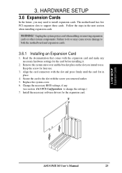
Secure the card to the slot with the screw you may cause severe damage to both the motherboard and expansion cards. 3.6.1 Installing an Expansion Card 1. H/W SETUP Expansion Cards ASUS P4T-M User's Manual 23 HARDWARE SETUP 3.6 Expansion Cards In the future, you removed earlier. 5. Unplug ... . (see section 4.4.3 PCI Configuration to install expansion cards. WARNING! Failure to do so may need to change the settings.) 7. The motherboard has five PCI expansion slots to use . 3. Keep the screw for the expansion card. 3. Replace the system cover. 6. Change the necessary...
Secure the card to the slot with the screw you may cause severe damage to both the motherboard and expansion cards. 3.6.1 Installing an Expansion Card 1. H/W SETUP Expansion Cards ASUS P4T-M User's Manual 23 HARDWARE SETUP 3.6 Expansion Cards In the future, you removed earlier. 5. Unplug ... . (see section 4.4.3 PCI Configuration to install expansion cards. WARNING! Failure to do so may need to change the settings.) 7. The motherboard has five PCI expansion slots to use . 3. Keep the screw for the expansion card. 3. Replace the system cover. 6. Change the necessary...

P4T-M User Manual
Page 24
If your motherboard also has MIDI enabled, another IRQ will make the system unstable or cards inoperable. 24 ASUS P4T-M User's Manual shared - shared -- -- - Interrupt Request Table for ISA or PCI devices. INT-C INT-D INT-E INT-F - - - shared used shared used - - IMPORTANT... IDE Channel *These IRQs are already in use . In a standard design, there are 16 IRQs available but most of them are usually available for this Motherboard PCI slot 1 PCI slot 2 PCI slot 3 AGP slot USB HC0 USB HC1 SMB AC'97 LAN IEEE 1394 INT-A INT-B -- -- -- H/W SETUP Expansion Cards 3. ...
If your motherboard also has MIDI enabled, another IRQ will make the system unstable or cards inoperable. 24 ASUS P4T-M User's Manual shared - shared -- -- - Interrupt Request Table for ISA or PCI devices. INT-C INT-D INT-E INT-F - - - shared used shared used - - IMPORTANT... IDE Channel *These IRQs are already in use . In a standard design, there are 16 IRQs available but most of them are usually available for this Motherboard PCI slot 1 PCI slot 2 PCI slot 3 AGP slot USB HC0 USB HC1 SMB AC'97 LAN IEEE 1394 INT-A INT-B -- -- -- H/W SETUP Expansion Cards 3. ...


