
Motherboard DIY Troubleshooting Guide
Page 1
® P4T-EM Intel® 850 ATX Motherboard USER'S MANUAL
® P4T-EM Intel® 850 ATX Motherboard USER'S MANUAL

Motherboard DIY Troubleshooting Guide
Page 2
... FOR ANY ERRORS OR INACCURACIES THAT MAY APPEAR IN THIS MANUAL, INCLUDING THE PRODUCTS AND SOFTWARE DESCRIBED IN IT. Product Name: ASUS P4T-EM Manual Revision: 1.00 E903 Release Date: November 2001 2 ASUS P4T-EM User's Manual or (2) the serial number of ASUSTeK COMPUTER INC. ("ASUS"). IN NO EVENT SHALL ASUS, ITS DIRECTORS, OFFICERS, EMPLOYEES OR AGENTS BE LIABLE FOR ANY...
... FOR ANY ERRORS OR INACCURACIES THAT MAY APPEAR IN THIS MANUAL, INCLUDING THE PRODUCTS AND SOFTWARE DESCRIBED IN IT. Product Name: ASUS P4T-EM Manual Revision: 1.00 E903 Release Date: November 2001 2 ASUS P4T-EM User's Manual or (2) the serial number of ASUSTeK COMPUTER INC. ("ASUS"). IN NO EVENT SHALL ASUS, ITS DIRECTORS, OFFICERS, EMPLOYEES OR AGENTS BE LIABLE FOR ANY...

Motherboard DIY Troubleshooting Guide
Page 3
...): +886-2-2890-7122 (English) Desktop/Server (Tel):+886-2-2890-7123 (English) Fax: +886-2-2980-7698 Email: tsd@asus.com.tw WWW: www.asus.com.tw FTP: ftp.asus.com.tw/pub/ASUS Newsgroup: csnews.asus.com.tw ASUS COMPUTER INTERNATIONAL (America) Marketing Address: 6737 Mowry Avenue, Mowry Business Center, Building 2 Newark, CA 94560, USA Fax: +1-510... Fax: +49-2102-9599-11 Support (Email): www.asuscom.de/de/support (for online support) WWW: www.asuscom.de FTP: ftp.asuscom.de/pub/ASUSCOM ASUS P4T-EM User's Manual 3
...): +886-2-2890-7122 (English) Desktop/Server (Tel):+886-2-2890-7123 (English) Fax: +886-2-2980-7698 Email: tsd@asus.com.tw WWW: www.asus.com.tw FTP: ftp.asus.com.tw/pub/ASUS Newsgroup: csnews.asus.com.tw ASUS COMPUTER INTERNATIONAL (America) Marketing Address: 6737 Mowry Avenue, Mowry Business Center, Building 2 Newark, CA 94560, USA Fax: +1-510... Fax: +49-2102-9599-11 Support (Email): www.asuscom.de/de/support (for online support) WWW: www.asuscom.de FTP: ftp.asuscom.de/pub/ASUSCOM ASUS P4T-EM User's Manual 3
Motherboard DIY Troubleshooting Guide
Page 4
HARDWARE SETUP 14 3.1 P4T-EM Motherboard Layout 14 3.2 Layout Contents 15 3.3 Hardware Setup Procedure 16 3.4 Motherboard Settings 16 3.5 System Memory 21 3.6 Central... Menu 56 4.4.1 Chip Configuration 59 4.4.2 I/O Device Configuration 61 4.4.3 PCI Configuration 63 4.4.4 Shadow Configuration 65 4.5 Power Menu 66 4 ASUS P4T-EM User's Manual FEATURES 8 2.1 The ASUS P4T-EM 8 2.1.1 Core Specifications 8 2.1.2 Connections 9 2.1.3 Optional Components 10 2.1.4 Performance and Intelligence 10 2.2 P4T-EM Motherboard Components 12 3. CONTENTS 1. INTRODUCTION 7 1.1 How This...
HARDWARE SETUP 14 3.1 P4T-EM Motherboard Layout 14 3.2 Layout Contents 15 3.3 Hardware Setup Procedure 16 3.4 Motherboard Settings 16 3.5 System Memory 21 3.6 Central... Menu 56 4.4.1 Chip Configuration 59 4.4.2 I/O Device Configuration 61 4.4.3 PCI Configuration 63 4.4.4 Shadow Configuration 65 4.5 Power Menu 66 4 ASUS P4T-EM User's Manual FEATURES 8 2.1 The ASUS P4T-EM 8 2.1.1 Core Specifications 8 2.1.2 Connections 9 2.1.3 Optional Components 10 2.1.4 Performance and Intelligence 10 2.2 P4T-EM Motherboard Components 12 3. CONTENTS 1. INTRODUCTION 7 1.1 How This...

Motherboard DIY Troubleshooting Guide
Page 5
APPENDIX 91 7.1 Glossary 91 INDEX 95 ASUS P4T-EM User's Manual 5 SOFTWARE REFERENCE 77 6.1 Winbond Smart Manager 77 6.2 ASUS PC Probe 81 6.3 ASUS Live Update 86 6.4 CyberLink PowerPlayer SE 87 6.5 CyberLink VideoLive Mail 88 7. CONTENTS 4.5.1 Power Up Control 68 4.5.2 Hardware Monitor 69 4.6 Boot Menu 70 4.7 Exit Menu 72 5.1 Install Operating System 74 5.2 Start Windows 74 5. SOFTWARE SETUP 75 5.3 P4T-EM Motherboard Support CD 75 6.
APPENDIX 91 7.1 Glossary 91 INDEX 95 ASUS P4T-EM User's Manual 5 SOFTWARE REFERENCE 77 6.1 Winbond Smart Manager 77 6.2 ASUS PC Probe 81 6.3 ASUS Live Update 86 6.4 CyberLink PowerPlayer SE 87 6.5 CyberLink VideoLive Mail 88 7. CONTENTS 4.5.1 Power Up Control 68 4.5.2 Hardware Monitor 69 4.6 Boot Menu 70 4.7 Exit Menu 72 5.1 Install Operating System 74 5.2 Start Windows 74 5. SOFTWARE SETUP 75 5.3 P4T-EM Motherboard Support CD 75 6.

Motherboard DIY Troubleshooting Guide
Page 6
... the Federal Register, National Archives and Records Administration, U.S. Cet appareil numérique de la classe B est conforme à la norme NMB-003 du Canada. 6 ASUS P4T-EM User's Manual FCC & DOC COMPLIANCE This device complies with Canadian ICES-003.
... the Federal Register, National Archives and Records Administration, U.S. Cet appareil numérique de la classe B est conforme à la norme NMB-003 du Canada. 6 ASUS P4T-EM User's Manual FCC & DOC COMPLIANCE This device complies with Canadian ICES-003.
Motherboard DIY Troubleshooting Guide
Page 7
...checklist Production information and specifications Intructions on motherboard) (2) ASUS C-RIMM Continuity RIMM Optional Items ASUS IrDA-compliant infrared module Two Rambus Memory Modules LAN Card: PCI-L3C920 1394 Card: PCI-1394E ASUS P4T-EM User's Manual 7 Intructions on setting up the BIOS Intructions on ...setting up the included software Reference material for (1) 5.25" and (2) 3.5" floppy disk drives (1) ASUS 2-port USB connector set with bracket (1) Bag...
...checklist Production information and specifications Intructions on motherboard) (2) ASUS C-RIMM Continuity RIMM Optional Items ASUS IrDA-compliant infrared module Two Rambus Memory Modules LAN Card: PCI-L3C920 1394 Card: PCI-1394E ASUS P4T-EM User's Manual 7 Intructions on setting up the BIOS Intructions on ...setting up the included software Reference material for (1) 5.25" and (2) 3.5" floppy disk drives (1) ASUS 2-port USB connector set with bracket (1) Bag...

Motherboard DIY Troubleshooting Guide
Page 8
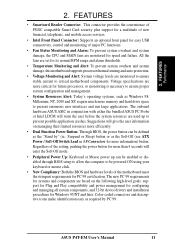
... controller with EPP and ECP capabilities. and two USB controllers for a total of up to 100MB/ sec; FEATURES 2.1 The ASUS P4T-EM The ASUS P4T-EM motherboard is required. • Intel® Accelerated Hub Architecture: Features a dedicated high speed hub link between the ICH2 and ...RDRAM. • Intel ICH2: The Intel I /O Controller and Firmware Hub) with a bandwidth of the processor's external frequency. 8 ASUS P4T-EM User's Manual UART2 can also be directed from COM2 to the Infrared Module for wireless connections. • PC800 Memory Support: Equipped with four Rambus Inline...
... controller with EPP and ECP capabilities. and two USB controllers for a total of up to 100MB/ sec; FEATURES 2.1 The ASUS P4T-EM The ASUS P4T-EM motherboard is required. • Intel® Accelerated Hub Architecture: Features a dedicated high speed hub link between the ICH2 and ...RDRAM. • Intel ICH2: The Intel I /O Controller and Firmware Hub) with a bandwidth of the processor's external frequency. 8 ASUS P4T-EM User's Manual UART2 can also be directed from COM2 to the Infrared Module for wireless connections. • PC800 Memory Support: Equipped with four Rambus Inline...

Motherboard DIY Troubleshooting Guide
Page 9
... component level interconnect targeted at 3D graphical applications using a 4X mode bus. The slot is okay. • ATX power connector. ASUS P4T-EM User's Manual 9 FEATURES Connections 2. One side of the connector is slotted to prevent incorrect insertion of the floppy disk cable. • Smartcard ... module for a PS/2 keyboard. • Onboard LED: Signals AC power is keyed to support only the latest 1.5 volt AGP cards: ASUS V3800 and newer versions. • CNR Support: A Communication and Networking Riser (CNR) slot provides an interface to support very affordable multichannel audio...
... component level interconnect targeted at 3D graphical applications using a 4X mode bus. The slot is okay. • ATX power connector. ASUS P4T-EM User's Manual 9 FEATURES Connections 2. One side of the connector is slotted to prevent incorrect insertion of the floppy disk cable. • Smartcard ... module for a PS/2 keyboard. • Onboard LED: Signals AC power is keyed to support only the latest 1.5 volt AGP cards: ASUS V3800 and newer versions. • CNR Support: A Communication and Networking Riser (CNR) slot provides an interface to support very affordable multichannel audio...

Motherboard DIY Troubleshooting Guide
Page 10
...operating systems (OS) supporting OS Direct Power Management (OSPM) functionality. This function ensures the best performance and reliability. 10 ASUS P4T-EM User's Manual When auto throttling is a new technology to -use interface for more Energy Saving Features for virtually automatic setup. ACPI ... manage system status information, such as CPU and systerm voltages, temperatures, and fan status through the onboard hardware and the bundled ASUS PC Probe or Intel LDCM software. • Desktop Management Interface (DMI): Supports DMI through BIOS, which allows hardware to communicate...
...operating systems (OS) supporting OS Direct Power Management (OSPM) functionality. This function ensures the best performance and reliability. 10 ASUS P4T-EM User's Manual When auto throttling is a new technology to -use interface for more Energy Saving Features for virtually automatic setup. ACPI ... manage system status information, such as CPU and systerm voltages, temperatures, and fan status through the onboard hardware and the bundled ASUS PC Probe or Intel LDCM software. • Desktop Management Interface (DMI): Supports DMI through BIOS, which allows hardware to communicate...
Motherboard DIY Troubleshooting Guide
Page 11
...descriptive icons make identification easy as the Soft-Off (see ATX Power / Soft-Off Switch Lead in conjunction with either the bundled ASUS PC Probe or Intel LDCM will give the user information on the following high-level goals: support for Plug and Play compatibility ... and installation procedures for more information) button. Regardless of the setting, pushing the power button for Windows 95/NT and later. ASUS P4T-EM User's Manual 11 FEATURES Performance 2. Voltage specifications are used up can be enabled or disabled through BIOS setup to allow the computer to prevent ...
...descriptive icons make identification easy as the Soft-Off (see ATX Power / Soft-Off Switch Lead in conjunction with either the bundled ASUS PC Probe or Intel LDCM will give the user information on the following high-level goals: support for Plug and Play compatibility ... and installation procedures for more information) button. Regardless of the setting, pushing the power button for Windows 95/NT and later. ASUS P4T-EM User's Manual 11 FEATURES Performance 2. Voltage specifications are used up can be enabled or disabled through BIOS setup to allow the computer to prevent ...

Motherboard DIY Troubleshooting Guide
Page 12
FEATURES 2.2 P4T-EM Motherboard Components See opposite page for Pentium 4 Processors 3 Chipsets Intel 850 Memory Controller Hub (MCH 5 Intel I/O Controller Hub 2 (ICH2 11 2Mbit Firmware Hub (...Line Out Connector Bottom) 22 1 Line In Connector Bottom) 22 1 Line Microphone Connector Bottom) 22 Hardware Monitoring ASUS onboard chipset 10 Power ATX Power Supply Connector 2 ATX 12V Power Supply Connector 4 Special Feature Onboard LED 14 Form Factor MicroATX 12 ASUS P4T-EM User's Manual 2. FEATURES MB Components 2. Location Processor Support Socket 478 for locations.
FEATURES 2.2 P4T-EM Motherboard Components See opposite page for Pentium 4 Processors 3 Chipsets Intel 850 Memory Controller Hub (MCH 5 Intel I/O Controller Hub 2 (ICH2 11 2Mbit Firmware Hub (...Line Out Connector Bottom) 22 1 Line In Connector Bottom) 22 1 Line Microphone Connector Bottom) 22 Hardware Monitoring ASUS onboard chipset 10 Power ATX Power Supply Connector 2 ATX 12V Power Supply Connector 4 Special Feature Onboard LED 14 Form Factor MicroATX 12 ASUS P4T-EM User's Manual 2. FEATURES MB Components 2. Location Processor Support Socket 478 for locations.

Motherboard DIY Troubleshooting Guide
Page 14
...478 COM2 Line Out Intel 850 Memory Controller Hub (MCH) GAME_AUDIO Line In Mic In AUX MODEM CD1 J11 J12 INTEL_FPANEL1 Audio Codec P4T-EM ATX12V CPU_FAN Accelerated Graphics Port (AGP) PCI1 OC3 J3J3+ Intel I/O HDDLED Controller Hub (ICH2) CLCMOS ADN SPDIFOUT Super I/O PCI2... SMB CNR_SLOT ® LED1 IR SMARTCON CHASSIS CR2032 3V Lithium Cell CMOS Power PANEL 2Mbit Firmware Hub FLOPPY ASUS ASIC USB2 Grayed components are available only on certain models at the time of purchase. 14 ASUS P4T-EM User's Manual H/W SETUP Motherboard Layout PRIMARY IDE 24.4cm (9.6in) 3. 3.
...478 COM2 Line Out Intel 850 Memory Controller Hub (MCH) GAME_AUDIO Line In Mic In AUX MODEM CD1 J11 J12 INTEL_FPANEL1 Audio Codec P4T-EM ATX12V CPU_FAN Accelerated Graphics Port (AGP) PCI1 OC3 J3J3+ Intel I/O HDDLED Controller Hub (ICH2) CLCMOS ADN SPDIFOUT Super I/O PCI2... SMB CNR_SLOT ® LED1 IR SMARTCON CHASSIS CR2032 3V Lithium Cell CMOS Power PANEL 2Mbit Firmware Hub FLOPPY ASUS ASIC USB2 Grayed components are available only on certain models at the time of purchase. 14 ASUS P4T-EM User's Manual H/W SETUP Motherboard Layout PRIMARY IDE 24.4cm (9.6in) 3. 3.
Motherboard DIY Troubleshooting Guide
Page 15
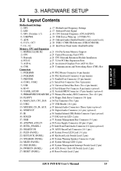
... (5-1 pin) 18) ATXPWR, ATX12V p.38 Power Supply Connector (20 pin) (4 pin) 19) INTEL_FPANEL1 p.39 Intel Front Panel Audio Connector (10-1 pin) (optional) 20) SMARTCON p.39 ASUS SmartCard Connector (14-1 pin ) 21) PLED (PANEL) p.40 System Power LED Lead (3-1 pin) 22) KEYLOCK (PANEL) p.40 Keyboard Lock Switch Lead (2 pin) 23) SPEAKER (PANEL... System Management Interrupt Switch Lead (2 pin) 26) PWRBTN (PANEL) p.40 ATX Power / Soft-Off Switch Lead (2 pin) 27) RESET (PANEL) p.40 Reset Switch Lead (2 pin) ASUS P4T-EM User's Manual 15
... (5-1 pin) 18) ATXPWR, ATX12V p.38 Power Supply Connector (20 pin) (4 pin) 19) INTEL_FPANEL1 p.39 Intel Front Panel Audio Connector (10-1 pin) (optional) 20) SMARTCON p.39 ASUS SmartCard Connector (14-1 pin ) 21) PLED (PANEL) p.40 System Power LED Lead (3-1 pin) 22) KEYLOCK (PANEL) p.40 Keyboard Lock Switch Lead (2 pin) 23) SPEAKER (PANEL... System Management Interrupt Switch Lead (2 pin) 26) PWRBTN (PANEL) p.40 ATX Power / Soft-Off Switch Lead (2 pin) 27) RESET (PANEL) p.40 Reset Switch Lead (2 pin) ASUS P4T-EM User's Manual 15

Motherboard DIY Troubleshooting Guide
Page 16
... to touch the IC chips, leads or connectors, or other components. 4. Place components on a grounded antistatic pad or on the inside. 2. H/W SETUP Getting Started 16 ASUS P4T-EM User's Manual
... to touch the IC chips, leads or connectors, or other components. 4. Place components on a grounded antistatic pad or on the inside. 2. H/W SETUP Getting Started 16 ASUS P4T-EM User's Manual

Motherboard DIY Troubleshooting Guide
Page 17
...motherboard frequency is lit, since the user risks electrical shock and/or disabling system configuration. The white block represents the switch's position. SW1 P4T-EM ® P4T-EM DIP Switches ON OFF 1. Frequency Selection 2. Frequency Selection 4. H/W SETUP Motherboard Settings 2) Onboard Power Signal (LED) The board LED ...3. Frequency Selection 5. Adding or removing devices is not advisable when the LED is adjusted through the DIP switches. P4T-EM ® P4T-EM Onboard LED ON Standby Power OFF Powered Off ASUS P4T-EM User's Manual 17 3. Frequency Selection 3.
...motherboard frequency is lit, since the user risks electrical shock and/or disabling system configuration. The white block represents the switch's position. SW1 P4T-EM ® P4T-EM DIP Switches ON OFF 1. Frequency Selection 2. Frequency Selection 4. H/W SETUP Motherboard Settings 2) Onboard Power Signal (LED) The board LED ...3. Frequency Selection 5. Adding or removing devices is not advisable when the LED is adjusted through the DIP switches. P4T-EM ® P4T-EM Onboard LED ON Standby Power OFF Powered Off ASUS P4T-EM User's Manual 17 3. Frequency Selection 3.

Motherboard DIY Troubleshooting Guide
Page 18
... Setting CPU 100.0MHz AGP 66.0MHz PCI 33.0MHz ON 12345 ON 12345 103.0MHz 68.0MHz 34.0MHz ON 12345 ON 12345 ® P4T-EM CPU External Frequency Selection CPU 105.0MHz AGP 70.0MHz PCI 35.0MHz 110.0MHz 73.0MHz 36.0MHz Frequency Table DSW CPU AGP PCI... send to the CPU, DRAM, and the PCI bus. This allows the selection of the CPU's External frequency (or BUS Clock). H/W SETUP Motherboard Settings 18 ASUS P4T-EM User's Manual 3.
... Setting CPU 100.0MHz AGP 66.0MHz PCI 33.0MHz ON 12345 ON 12345 103.0MHz 68.0MHz 34.0MHz ON 12345 ON 12345 ® P4T-EM CPU External Frequency Selection CPU 105.0MHz AGP 70.0MHz PCI 35.0MHz 110.0MHz 73.0MHz 36.0MHz Frequency Table DSW CPU AGP PCI... send to the CPU, DRAM, and the PCI bus. This allows the selection of the CPU's External frequency (or BUS Clock). H/W SETUP Motherboard Settings 18 ASUS P4T-EM User's Manual 3.

Motherboard DIY Troubleshooting Guide
Page 19
... Set the jumpers to +5VSB to allow wake up (USBPWR) The jumpers are set to support the other mode). P4T-EM USBPWR 2 1 +5VSB 3 2 +5V (Default) ® P4T-EM USB Device Wake Up 5) Onboard Audio Setting (ADN) (audio models only) The onboard Audio Codec may be enabled...up from the S1 sleep state (CPU stopped; NOTES: 1. Setting Enable Disable ADN [1-2] (default) [2-3] P4T-EM ® P4T-EM AUDIO Setting ADN 3 2 2 1 ENABLE AUDIO (Default) DISABLE AUDIO ASUS P4T-EM User's Manual 19 This feature requires an ATX power supply that can supply at least 2A on a CNR slot (...
... Set the jumpers to +5VSB to allow wake up (USBPWR) The jumpers are set to support the other mode). P4T-EM USBPWR 2 1 +5VSB 3 2 +5V (Default) ® P4T-EM USB Device Wake Up 5) Onboard Audio Setting (ADN) (audio models only) The onboard Audio Codec may be enabled...up from the S1 sleep state (CPU stopped; NOTES: 1. Setting Enable Disable ADN [1-2] (default) [2-3] P4T-EM ® P4T-EM AUDIO Setting ADN 3 2 2 1 ENABLE AUDIO (Default) DISABLE AUDIO ASUS P4T-EM User's Manual 19 This feature requires an ATX power supply that can supply at least 2A on a CNR slot (...

Motherboard DIY Troubleshooting Guide
Page 20
... USB hub CNR card is used. (See page 39 for the INTEL_FPANEL1 connector.) J11 J12 P4T-EM ® P4T-EM Internal Line Out Connectors LAP_LT LAP_LTT LAP_RT LAP_RTT 20 ASUS P4T-EM User's Manual The caps-on both J11 and J12, adjacent to control selection of regular audio external connectors, .... Do not remove the jumper caps unless the INTEL_FPANEL1 cable connector is used to the INTEL_FPANEL1 connector. 3. H/W SETUP Motherboard Settings P4T-EM ® P4T-EM CNR/USB Selection 2 1 USB2 (Default) 3 2 CNRUSB 7) Intel Front Panel Audio Selection (J11, J12) The motherboard ships...
... USB hub CNR card is used. (See page 39 for the INTEL_FPANEL1 connector.) J11 J12 P4T-EM ® P4T-EM Internal Line Out Connectors LAP_LT LAP_LTT LAP_RT LAP_RTT 20 ASUS P4T-EM User's Manual The caps-on both J11 and J12, adjacent to control selection of regular audio external connectors, .... Do not remove the jumper caps unless the INTEL_FPANEL1 cable connector is used to the INTEL_FPANEL1 connector. 3. H/W SETUP Motherboard Settings P4T-EM ® P4T-EM CNR/USB Selection 2 1 USB2 (Default) 3 2 CNRUSB 7) Intel Front Panel Audio Selection (J11, J12) The motherboard ships...
Motherboard DIY Troubleshooting Guide
Page 21
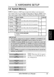
... identical (see below). 2. b. 128MB RDRAM RIMMB2 C-RIMM RIMMB1 128MB RDRAM C-RIMM RIMMA2 RIMMA1 c. 128MB RDRAM RIMMB2 128MB RDRAM RIMMB1 128MB RDRAM 128MB RDRAM RIMMA2 RIMMA1 ASUS P4T-EM User's Manual 21 a. When C-RIMMs are a serial connection in this motherboard. C-RIMMs (Continuity RIMM) must be used in a Rambus interface, such as used to complete the...
... identical (see below). 2. b. 128MB RDRAM RIMMB2 C-RIMM RIMMB1 128MB RDRAM C-RIMM RIMMA2 RIMMA1 c. 128MB RDRAM RIMMB2 128MB RDRAM RIMMB1 128MB RDRAM 128MB RDRAM RIMMA2 RIMMA1 ASUS P4T-EM User's Manual 21 a. When C-RIMMs are a serial connection in this motherboard. C-RIMMs (Continuity RIMM) must be used in a Rambus interface, such as used to complete the...


