
Motherboard DIY Troubleshooting Guide
Page 1
® P4T-EM Intel® 850 ATX Motherboard USER'S MANUAL
® P4T-EM Intel® 850 ATX Motherboard USER'S MANUAL
Motherboard DIY Troubleshooting Guide
Page 4
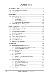
... 3.8 External Connectors 30 3.9 Starting Up the First Time 41 4. INTRODUCTION 7 1.1 How This Manual Is Organized 7 1.2 Item Checklist 7 2. CONTENTS 1. FEATURES 8 2.1 The ASUS P4T-EM 8 2.1.1 Core Specifications 8 2.1.2 Connections 9 2.1.3 Optional Components 10 2.1.4 Performance and Intelligence 10 2.2 P4T-EM Motherboard Components 12 3. BIOS SETUP 43 4.1 Managing and Updating Your BIOS 43 4.1.1 Upon First Use of the Computer System 43 4.1.2 Updating...
... 3.8 External Connectors 30 3.9 Starting Up the First Time 41 4. INTRODUCTION 7 1.1 How This Manual Is Organized 7 1.2 Item Checklist 7 2. CONTENTS 1. FEATURES 8 2.1 The ASUS P4T-EM 8 2.1.1 Core Specifications 8 2.1.2 Connections 9 2.1.3 Optional Components 10 2.1.4 Performance and Intelligence 10 2.2 P4T-EM Motherboard Components 12 3. BIOS SETUP 43 4.1 Managing and Updating Your BIOS 43 4.1.1 Upon First Use of the Computer System 43 4.1.2 Updating...

Motherboard DIY Troubleshooting Guide
Page 5
SOFTWARE REFERENCE 77 6.1 Winbond Smart Manager 77 6.2 ASUS PC Probe 81 6.3 ASUS Live Update 86 6.4 CyberLink PowerPlayer SE 87 6.5 CyberLink VideoLive Mail 88 7. APPENDIX 91 7.1 Glossary 91 INDEX 95 ASUS P4T-EM User's Manual 5 SOFTWARE SETUP 75 5.3 P4T-EM Motherboard Support CD 75 6. CONTENTS 4.5.1 Power Up Control 68 4.5.2 Hardware Monitor 69 4.6 Boot Menu 70 4.7 Exit Menu 72 5.1 Install Operating System 74 5.2 Start Windows 74 5.
SOFTWARE REFERENCE 77 6.1 Winbond Smart Manager 77 6.2 ASUS PC Probe 81 6.3 ASUS Live Update 86 6.4 CyberLink PowerPlayer SE 87 6.5 CyberLink VideoLive Mail 88 7. APPENDIX 91 7.1 Glossary 91 INDEX 95 ASUS P4T-EM User's Manual 5 SOFTWARE SETUP 75 5.3 P4T-EM Motherboard Support CD 75 6. CONTENTS 4.5.1 Power Up Control 68 4.5.2 Hardware Monitor 69 4.6 Boot Menu 70 4.7 Exit Menu 72 5.1 Install Operating System 74 5.2 Start Windows 74 5.
Motherboard DIY Troubleshooting Guide
Page 7
... Check that your retailer. APPENDIX Manual information and checklist Production information and specifications Intructions on motherboard) (2) ASUS C-RIMM Continuity RIMM Optional Items ASUS IrDA-compliant infrared module Two Rambus Memory Modules LAN Card: PCI-L3C920 1394 Card: PCI-1394E ASUS P4T-EM User's Manual 7 BIOS SETUP 5. INTRODUCTION 1.1 How This Manual Is Organized This manual is complete...
... Check that your retailer. APPENDIX Manual information and checklist Production information and specifications Intructions on motherboard) (2) ASUS C-RIMM Continuity RIMM Optional Items ASUS IrDA-compliant infrared module Two Rambus Memory Modules LAN Card: PCI-L3C920 1394 Card: PCI-1394E ASUS P4T-EM User's Manual 7 BIOS SETUP 5. INTRODUCTION 1.1 How This Manual Is Organized This manual is complete...

Motherboard DIY Troubleshooting Guide
Page 8
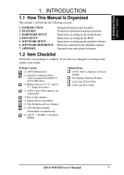
FEATURES 2.1 The ASUS P4T-EM The ASUS P4T-EM motherboard is required. • Intel® Accelerated Hub Architecture: Features a dedicated high speed hub link between the ICH2 and MCH with two connectors that support four ... manual adjustment of 4 USB ports. • Low Pin Count (LPC) Super Multi-I /O Controller Hub 2 (82801 ICH2) features support for a total of the processor's external frequency. 8 ASUS P4T-EM User's Manual and dual channel RDRAM. • Intel ICH2: The Intel I /O: Provides two high-speed UART ompatible serial ports and one parallel port with EPP...
FEATURES 2.1 The ASUS P4T-EM The ASUS P4T-EM motherboard is required. • Intel® Accelerated Hub Architecture: Features a dedicated high speed hub link between the ICH2 and MCH with two connectors that support four ... manual adjustment of 4 USB ports. • Low Pin Count (LPC) Super Multi-I /O Controller Hub 2 (82801 ICH2) features support for a total of the processor's external frequency. 8 ASUS P4T-EM User's Manual and dual channel RDRAM. • Intel ICH2: The Intel I /O: Provides two high-speed UART ompatible serial ports and one parallel port with EPP...

Motherboard DIY Troubleshooting Guide
Page 10
... operating systems (OS) supporting OS Direct Power Management (OSPM) functionality. This function ensures the best performance and reliability. 10 ASUS P4T-EM User's Manual FEATURES Options / Performance 2. With these features implemented in firmware-based virus protection, and autodetection of compatibility. (...Requires DMI-enabled components.) • Auto CPU Throttling Function: Incorporated into this motherboard is enabled, the CPU with a peak bandwidth of its duty cycle when temperature lowers to wait for a long time for...
... operating systems (OS) supporting OS Direct Power Management (OSPM) functionality. This function ensures the best performance and reliability. 10 ASUS P4T-EM User's Manual FEATURES Options / Performance 2. With these features implemented in firmware-based virus protection, and autodetection of compatibility. (...Requires DMI-enabled components.) • Auto CPU Throttling Function: Incorporated into this motherboard is enabled, the CPU with a peak bandwidth of its duty cycle when temperature lowers to wait for a long time for...
Motherboard DIY Troubleshooting Guide
Page 11
...Off (see ATX Power / Soft-Off Switch Lead in conjunction with either the bundled ASUS PC Probe or Intel LDCM will give the user information on the following high-level ... • Temperature Monitoring and Alert: To prevent system overheat and system damage, this motherboard supports processor thermal sensing and auto-protection. • Voltage Monitoring and Alert: System ... Connector: Supports an optional front panel for easy USB connectivity, control and monitoring of the motherboard meet the stringent requirements for more efficiently. • Dual Function Power Button: Through BIOS...
...Off (see ATX Power / Soft-Off Switch Lead in conjunction with either the bundled ASUS PC Probe or Intel LDCM will give the user information on the following high-level ... • Temperature Monitoring and Alert: To prevent system overheat and system damage, this motherboard supports processor thermal sensing and auto-protection. • Voltage Monitoring and Alert: System ... Connector: Supports an optional front panel for easy USB connectivity, control and monitoring of the motherboard meet the stringent requirements for more efficiently. • Dual Function Power Button: Through BIOS...

Motherboard DIY Troubleshooting Guide
Page 12
2. Location Processor Support Socket 478 for locations. FEATURES 2.2 P4T-EM Motherboard Components See opposite page for Pentium 4 Processors 3 Chipsets Intel 850 Memory Controller Hub (MCH 5 Intel I/O Controller Hub 2 (ICH2 11 2Mbit Firmware Hub (FWH 13...SPDIF Connector 19 1 Game/MIDI Connector Top) 22 1 Line Out Connector Bottom) 22 1 Line In Connector Bottom) 22 1 Line Microphone Connector Bottom) 22 Hardware Monitoring ASUS onboard chipset 10 Power ATX Power Supply Connector 2 ATX 12V Power Supply Connector 4 Special Feature Onboard LED 14 Form Factor MicroATX 12...
2. Location Processor Support Socket 478 for locations. FEATURES 2.2 P4T-EM Motherboard Components See opposite page for Pentium 4 Processors 3 Chipsets Intel 850 Memory Controller Hub (MCH 5 Intel I/O Controller Hub 2 (ICH2 11 2Mbit Firmware Hub (FWH 13...SPDIF Connector 19 1 Game/MIDI Connector Top) 22 1 Line Out Connector Bottom) 22 1 Line In Connector Bottom) 22 1 Line Microphone Connector Bottom) 22 Hardware Monitoring ASUS onboard chipset 10 Power ATX Power Supply Connector 2 ATX 12V Power Supply Connector 4 Special Feature Onboard LED 14 Form Factor MicroATX 12...

Motherboard DIY Troubleshooting Guide
Page 14
HARDWARE SETUP 3.1 P4T-EM Motherboard Layout PS/2KBMS T: Mouse B: Keyboard Bottom: Top: USB1 RJ-... 850 Memory Controller Hub (MCH) GAME_AUDIO Line In Mic In AUX MODEM CD1 J11 J12 INTEL_FPANEL1 Audio Codec P4T-EM ATX12V CPU_FAN Accelerated Graphics Port (AGP) PCI1 OC3 J3J3+ Intel I/O HDDLED Controller Hub (ICH2) CLCMOS ADN...CR2032 3V Lithium Cell CMOS Power PANEL 2Mbit Firmware Hub FLOPPY ASUS ASIC USB2 Grayed components are available only on certain models at the time of purchase. 14 ASUS P4T-EM User's Manual 3. H/W SETUP Motherboard Layout PRIMARY IDE 24.4cm (9.6in) 3.
HARDWARE SETUP 3.1 P4T-EM Motherboard Layout PS/2KBMS T: Mouse B: Keyboard Bottom: Top: USB1 RJ-... 850 Memory Controller Hub (MCH) GAME_AUDIO Line In Mic In AUX MODEM CD1 J11 J12 INTEL_FPANEL1 Audio Codec P4T-EM ATX12V CPU_FAN Accelerated Graphics Port (AGP) PCI1 OC3 J3J3+ Intel I/O HDDLED Controller Hub (ICH2) CLCMOS ADN...CR2032 3V Lithium Cell CMOS Power PANEL 2Mbit Firmware Hub FLOPPY ASUS ASIC USB2 Grayed components are available only on certain models at the time of purchase. 14 ASUS P4T-EM User's Manual 3. H/W SETUP Motherboard Layout PRIMARY IDE 24.4cm (9.6in) 3.
Motherboard DIY Troubleshooting Guide
Page 15
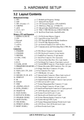
3. H/W SETUP Layout Contents 3. HARDWARE SETUP 3.2 Layout Contents Motherboard Settings 1) SW1 p. 17 Motherboard Frequency Settings 2) LED p. 17 Onboard Power Signal 3) SW1 (Switches 1-5) p. 18 CPU External Frequency ...Supply Connector (20 pin) (4 pin) 19) INTEL_FPANEL1 p.39 Intel Front Panel Audio Connector (10-1 pin) (optional) 20) SMARTCON p.39 ASUS SmartCard Connector (14-1 pin ) 21) PLED (PANEL) p.40 System Power LED Lead (3-1 pin) 22) KEYLOCK (PANEL) p.40 Keyboard ...Off Switch Lead (2 pin) 27) RESET (PANEL) p.40 Reset Switch Lead (2 pin) ASUS P4T-EM User's Manual 15
3. H/W SETUP Layout Contents 3. HARDWARE SETUP 3.2 Layout Contents Motherboard Settings 1) SW1 p. 17 Motherboard Frequency Settings 2) LED p. 17 Onboard Power Signal 3) SW1 (Switches 1-5) p. 18 CPU External Frequency ...Supply Connector (20 pin) (4 pin) 19) INTEL_FPANEL1 p.39 Intel Front Panel Audio Connector (10-1 pin) (optional) 20) SMARTCON p.39 ASUS SmartCard Connector (14-1 pin ) 21) PLED (PANEL) p.40 System Power LED Lead (3-1 pin) 22) KEYLOCK (PANEL) p.40 Keyboard ...Off Switch Lead (2 pin) 27) RESET (PANEL) p.40 Reset Switch Lead (2 pin) ASUS P4T-EM User's Manual 15

Motherboard DIY Troubleshooting Guide
Page 16
... your computer. 1. For heavily-loaded configurations, an ATX12V power supply of your computer: 1. WARNING! Configure the BIOS parameter settings 3.4 Motherboard Settings This section tells you do not have one, touch both of 300W may be required. Install Expansion Cards 5. For typical system configurations...least 230W and at least 8.5A on the inside. 2. H/W SETUP Getting Started 16 ASUS P4T-EM User's Manual To protect them against damage from the system. 5. Hold components by the edges and try not to change motherboard function settings through the switches and/or jumpers.
... your computer. 1. For heavily-loaded configurations, an ATX12V power supply of your computer: 1. WARNING! Configure the BIOS parameter settings 3.4 Motherboard Settings This section tells you do not have one, touch both of 300W may be required. Install Expansion Cards 5. For typical system configurations...least 230W and at least 8.5A on the inside. 2. H/W SETUP Getting Started 16 ASUS P4T-EM User's Manual To protect them against damage from the system. 5. Hold components by the edges and try not to change motherboard function settings through the switches and/or jumpers.

Motherboard DIY Troubleshooting Guide
Page 17
...P4T-EM ® P4T-EM Onboard LED ON Standby Power OFF Powered Off ASUS P4T-EM User's Manual 17 The white block represents the switch's position. Frequency Selection. 3. ON 12345 3. HARDWARE SETUP 1) Motherboard Frequency Settings (SW1) The motherboard frequency is lit, since the user risks electrical shock and/or disabling system configuration. Frequency Selection 2. Frequency Selection 5. H/W SETUP Motherboard... when the LED is adjusted through the DIP switches. Frequency Selection 3. SW1 P4T-EM ® P4T-EM DIP Switches ON OFF 1. Frequency Selection 4.
...P4T-EM ® P4T-EM Onboard LED ON Standby Power OFF Powered Off ASUS P4T-EM User's Manual 17 The white block represents the switch's position. Frequency Selection. 3. ON 12345 3. HARDWARE SETUP 1) Motherboard Frequency Settings (SW1) The motherboard frequency is lit, since the user risks electrical shock and/or disabling system configuration. Frequency Selection 2. Frequency Selection 5. H/W SETUP Motherboard... when the LED is adjusted through the DIP switches. Frequency Selection 3. SW1 P4T-EM ® P4T-EM DIP Switches ON OFF 1. Frequency Selection 4.

Motherboard DIY Troubleshooting Guide
Page 18
... not recommended. Set the CPU frequency only to the CPU, DRAM, and the PCI bus. Overclocking the processor is set at 100/66/ 33. H/W SETUP Motherboard Settings 18 ASUS P4T-EM User's Manual Frequencies other than the recommended CPU bus frequencies are not guaranteed to be stable. It may result in a slower speed...
... not recommended. Set the CPU frequency only to the CPU, DRAM, and the PCI bus. Overclocking the processor is set at 100/66/ 33. H/W SETUP Motherboard Settings 18 ASUS P4T-EM User's Manual Frequencies other than the recommended CPU bus frequencies are not guaranteed to be stable. It may result in a slower speed...

Motherboard DIY Troubleshooting Guide
Page 19
... wake up . 2. H/W SETUP Motherboard Settings 3. NOTES: 1. The total current consumed must NOT exceed the power supply capability (+5VSB) whether under normal working conditions or in low power mode) using the connected USB devices. 3. Setting Enable Disable ADN [1-2] (default) [2-3] P4T-EM ® P4T-EM AUDIO Setting ADN 3 2 2 1 ENABLE AUDIO (Default) DISABLE AUDIO ASUS P4T-EM User's Manual 19 Otherwise...
... wake up . 2. H/W SETUP Motherboard Settings 3. NOTES: 1. The total current consumed must NOT exceed the power supply capability (+5VSB) whether under normal working conditions or in low power mode) using the connected USB devices. 3. Setting Enable Disable ADN [1-2] (default) [2-3] P4T-EM ® P4T-EM AUDIO Setting ADN 3 2 2 1 ENABLE AUDIO (Default) DISABLE AUDIO ASUS P4T-EM User's Manual 19 Otherwise...

Motherboard DIY Troubleshooting Guide
Page 20
... connector is for the INTEL_FPANEL1 connector.) J11 J12 P4T-EM ® P4T-EM Internal Line Out Connectors LAP_LT LAP_LTT LAP_RT LAP_RTT 20 ASUS P4T-EM User's Manual HARDWARE SETUP 6) USB2 / CNRUSB Selection (J3-J3+, OC3) The CNR slot can support an optional USB hub CNR card. H/W SETUP Motherboard Settings P4T-EM ® P4T-EM CNR/USB Selection 2 1 USB2 (Default) 3 2 CNRUSB 7) Intel Front...
... connector is for the INTEL_FPANEL1 connector.) J11 J12 P4T-EM ® P4T-EM Internal Line Out Connectors LAP_LT LAP_LTT LAP_RT LAP_RTT 20 ASUS P4T-EM User's Manual HARDWARE SETUP 6) USB2 / CNRUSB Selection (J3-J3+, OC3) The CNR slot can support an optional USB hub CNR card. H/W SETUP Motherboard Settings P4T-EM ® P4T-EM CNR/USB Selection 2 1 USB2 (Default) 3 2 CNRUSB 7) Intel Front...
Motherboard DIY Troubleshooting Guide
Page 21
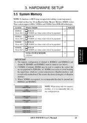
...b. 128MB RDRAM RIMMB2 C-RIMM RIMMB1 128MB RDRAM C-RIMM RIMMA2 RIMMA1 c. 128MB RDRAM RIMMB2 128MB RDRAM RIMMB1 128MB RDRAM 128MB RDRAM RIMMA2 RIMMA1 ASUS P4T-EM User's Manual 21 This assures the electrical integrity of channel A (RIMMA1 and RIMMA2) and channel B (RIMMB1 and RIMMB2) must be... identical (see below). 2. C-RIMMs (Continuity RIMM) must be used in this motherboard. a. HARDWARE SETUP 3.5 System Memory NOTE: No hardware or BIOS setup is recommended that they be populated) TOTAL SYSTEM MEMORY = (2GB...
...b. 128MB RDRAM RIMMB2 C-RIMM RIMMB1 128MB RDRAM C-RIMM RIMMA2 RIMMA1 c. 128MB RDRAM RIMMB2 128MB RDRAM RIMMB1 128MB RDRAM 128MB RDRAM RIMMA2 RIMMA1 ASUS P4T-EM User's Manual 21 This assures the electrical integrity of channel A (RIMMA1 and RIMMA2) and channel B (RIMMB1 and RIMMB2) must be... identical (see below). 2. C-RIMMs (Continuity RIMM) must be used in this motherboard. a. HARDWARE SETUP 3.5 System Memory NOTE: No hardware or BIOS setup is recommended that they be populated) TOTAL SYSTEM MEMORY = (2GB...

Motherboard DIY Troubleshooting Guide
Page 23
... 478 and open it snaps into the socket to scrape the motherboard surface when mounting a clamp-style processor fan, or else damage may not be attached to the CPU to the hinge of the socket base nearest to prevent overheating. ASUS P4T-EM User's Manual 23 Purchase and install a fan and heatsink before turning...
... 478 and open it snaps into the socket to scrape the motherboard surface when mounting a clamp-style processor fan, or else damage may not be attached to the CPU to the hinge of the socket base nearest to prevent overheating. ASUS P4T-EM User's Manual 23 Purchase and install a fan and heatsink before turning...

Motherboard DIY Troubleshooting Guide
Page 24
... the Heatsink Place the heatsink on top of the unit, not on the motherboard. Without sufficient circulation, the processor could overheat and damage both the processor and the motherboard. If a CPU is already installed on the shorter side. 24 ASUS P4T-EM User's Manual Make sure that your CPU fan is sufficient air circulation across...
... the Heatsink Place the heatsink on top of the unit, not on the motherboard. Without sufficient circulation, the processor could overheat and damage both the processor and the motherboard. If a CPU is already installed on the shorter side. 24 ASUS P4T-EM User's Manual Make sure that your CPU fan is sufficient air circulation across...

Motherboard DIY Troubleshooting Guide
Page 26
... fan, heatsink, and the retention mechanism in place. HARDWARE SETUP Step 3: Lock the Retention Mechanism Push down the locks on the motherboard labelled CPUFAN. 3. CPU Fan Connector (CPUFAN) 26 ASUS P4T-EM User's Manual With the added weight of the CPU fan and heatsink locking brace, no extra force is required to the fan...
... fan, heatsink, and the retention mechanism in place. HARDWARE SETUP Step 3: Lock the Retention Mechanism Push down the locks on the motherboard labelled CPUFAN. 3. CPU Fan Connector (CPUFAN) 26 ASUS P4T-EM User's Manual With the added weight of the CPU fan and heatsink locking brace, no extra force is required to the fan...
Motherboard DIY Troubleshooting Guide
Page 75
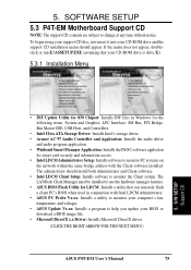
...The administrator should appear. 5. SOFTWARE SETUP 5.3 P4T-EM Motherboard Support CD NOTE: The support CD contents are ...Installation Menu 5. The LANDesk Client Manager must be installed to use the hardware manager features. • ASUS BIOS Flash Utility for smart card security and information access. • Intel LDCM Administrator Setup: Installs ...• Microsoft DirectX x.x Driver: Installs Microsoft DirectX driver. (CLICK THE RIGHT ARROW FOR THE NEXT MENU) ASUS P4T-EM User's Manual 75 S/W SETUP Support CD • INF Update Utility for 850 Chipset: Installs INF files in...
...The administrator should appear. 5. SOFTWARE SETUP 5.3 P4T-EM Motherboard Support CD NOTE: The support CD contents are ...Installation Menu 5. The LANDesk Client Manager must be installed to use the hardware manager features. • ASUS BIOS Flash Utility for smart card security and information access. • Intel LDCM Administrator Setup: Installs ...• Microsoft DirectX x.x Driver: Installs Microsoft DirectX driver. (CLICK THE RIGHT ARROW FOR THE NEXT MENU) ASUS P4T-EM User's Manual 75 S/W SETUP Support CD • INF Update Utility for 850 Chipset: Installs INF files in...


